
Introduction
If you're a Framework Laptop 13 (11th Gen Intel® Core™) system or Mainboard owner, have run into needing to reset your Mainboard, and have familiarity with soldering, you can request a free RTC Battery Substitute module through Support and follow this guide. To make the request process go smoothly, select "Problem with my Framework Laptop" as the category and enter the email address that you ordered the 11th Gen product on. If you don't have access to that email, include photos of the system and Mainboard serial numbers. The Mainboard serial number is located on the label between the Memory slots, while the system serial is located in the bottom right Expansion Card slot (when the system is upside down), and you can attach the photos to the email response that you receive from the support system.
Framework Laptop 13 (11th Gen Intel® Core™) requires an RTC battery (also known as a CMOS battery) to be present in order to boot the system. If the RTC battery voltage falls below a certain level, on some systems, the CPU can enter a bad state. This requires resetting the Mainboard and recharging the RTC battery. If the RTC battery repeatedly gets drained, the capacity will degrade, requiring the coin cell to be replaced.
As an alternative to this, we've created an RTC Battery Substitute module that can be inserted in place of the coin cell, allowing the RTC circuit to remain powered whenever either the main battery or external power is present. We've released the design files for this on GitHub as well for reference.
Note that some intermediate level of soldering skill is required for this. Only one side of one wire needs to be soldered, but it is being soldered to a fairly valuable Mainboard. We don't recommend taking this on unless you are confident in your soldering skills and have the necessary equipment.
Note that on 12th Gen and later systems, the RTC battery is not required, so this guide is only relevant for 11th Gen.
Tools
Parts
-
-
Before soldering, you should remove the Mainboard from the system, following the Mainboard guide up to Step 16.
-
-
-
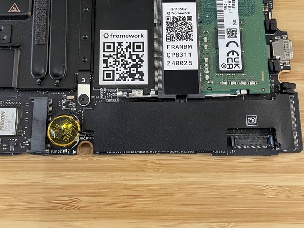
Using a SIM Eject tool or another small pin (such as a paperclip), carefully insert the pin into the hole at the bottom edge of the coin cell receptacle, and tilt it down to eject the coin cell battery. Please use caution here as improper removal can potentially result in damage to the RTC cradle.
-
Safely store or dispose of the coin cell battery at a recycling facility that can handle batteries. Keep coin cell batteries out of reach of children, as there is extreme danger if swallowed.
-
-
-
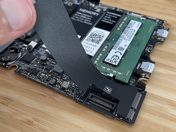
Peel back and remove the black mylar cover that is to the right of the coin cell socket. Set it aside, as you will need to re-use it later.
-
Carefully insert the RTC Battery Substitute into the coin cell socket. Start with the top side, and very carefully push it into place, using the SIM eject tool or pin from earlier to gently tilt the socket open if needed. Note that the socket is fragile, so be extra careful to not use too much force here.
-
Note that on the RTC Battery Substitute, there are two flat spots on the sides where there is no copper present. Make sure those areas are not in the location where they would touch the contact in the coin cell socket, as that would prevent electrical connection. You can check the image to see an orientation that works.
-
Note that you need to keep the clear yellow kapton tape on the RTC Battery Substitute. This is needed to avoid shorting the circuit to the Input Cover above it.
-
-
-
You'll now solder the wire to the 17.6V rail on the Mainboard. Get your soldering iron warmed up, and get some lead-free solder to use. Note that a fine chisel tip is the best shape to use if you have one available for your soldering iron.
-
Bend the wire into place so that it is near the right side of the capacitor that is above the PL331 marking. Don't worry if it touches the smaller capacitor that is above that, as that capacitor is connected to the same circuit.
-
Using your soldering iron and a very small amount of solder, solder the wire onto the right side of the capacitor. Use a magnifying glass or microscope to check that the solder connection is good and that there isn't excess solder bridging to a different area.
-
Once you are sure the wire is good, you can put the black mylar cover back into place.
-


Once you're done, you can follow the instructions in the Mainboard guide starting at Step 17 to put the Mainboard back into the system. Note that since there is no longer a real RTC battery, disconnecting the main battery will result in the clock being reset. When you reboot, the OS will pull the correct time off of a network time server.
Once you're done, you can follow the instructions in the Mainboard guide starting at Step 17 to put the Mainboard back into the system. Note that since there is no longer a real RTC battery, disconnecting the main battery will result in the clock being reset. When you reboot, the OS will pull the correct time off of a network time server.
Cancel: I did not complete this guide.
20 other people completed this guide.
20 Comments
I think I was able to manage this repair. For someone with almost non-existent soldering experience (despite the advice not to try this repair), I think it was not too difficult after looking up some basic soldering tutorials and doing some practices on prototype boards.
However, the caveats are
1. You need good dexterity.
2. The component that you are soldering the module to is much smaller than what the image seems to suggest. Like less than the throughholes of prototype boards. I just eyeballed it, but it would be helpful to also have some alligator clip + magnifying glass setup.
It would've been nice to have Framework do these steps since this issue is somewhat prevalent, but I guess I also gained experience (at a potentially costly risk)
Joo-Hyun Kim - Open Reply
I just did this repair: It's possible to get parts the kapton/isolating tape on top of the "battery side" of the substitution kit wedged into the receptacle - this will make the contact unreliable or break it. Make sure it's not in there and blocks the contact, that happened here first.
Other that that, other than being a little fiddly/scary to install the substitution seems to work fine so far.
Timm Lempfer - Open Reply
I just performed this repair, I think successfully. It was deeply unpleasant. The battery is nerve-wracking to put in, and I find the instructions regarding orientation confusing. There needs to be more photos, of the replacement part itself and which parts of it are exposed. By far the most difficult part is the soldering itself. The wire is extremely small, the capacitor is extremely small. The wire is so small it doesn't want to "tin", get solder on it. I was forced to load my soldering iron with solder, touch the capacitor edge first, then insert the wire into the blob of solder there. To inspect, a magnifying glass is NOT enough. I used a jewlers glasses; ideally you'd have a binocular microscope designed for electronics repair, such that the objective lens remains far from the work so you can solder. Framework should have done this repair in-house at their expense, since it was their design flaw.
Josh Rehman - Open Reply
I would be extremely cautious in undertaking this. The replacement part is not shaped the same around the rim as the battery it is replacing. The replacement has an abrupt 90 degree corner around the cylinder edge on both sides; the battery it is replacing has a rounded edge on the bottom and a recessed edge on the plus side. As a result, while it is relatively easy to slip the battery under the tangs of the plastic clip which holds it in place (both top and bottom), it is much more difficult to fit the replacement part under the prongs of the plastic clip -- the bottom of the cylindrical replacement is wider than the bottom of the battery. The bottom edge of the cylinder doesn't easily fit under the top clip. If it isn't under the prongs at the top, the bottom bracket will break off when you try to snap it in place. I had little trouble replacing the battery; when I went back to replace the battery with the substitute part, I snapped off the bottom bracket. Poor design.
Gary Aitken - Resolved on Release Reply
I just came across and contacted Framework for this fix and hope it works. After replacing the battery twice and having the laptop be an expensive paper weight for the last few months I had given up on the laptop and Framework in general. I hope this turns things around.
Paul Bilodeau - Resolved on Release Reply
Well, I got the part, had it professionally installed. Didn't work. Laptop has resumed its position as an expensive paper weight. I'm done with Frame Work.
The replacement itself was made as easily as possible. I didn't remove the mainboard, just unplugged the battery. Feels like way more trouble and risk of damaging connectors than it's worth to pull out the mainboard. Everything is very accessible without doing that.
The process of taking a physical picture of the mainboard to get the replacement sent out after I had already provided the SN was an annoying requirement.
Ryan Crisp - Resolved on Release Reply
It shouldn't be necessary to submit any of that information (pictures and serial numbers) to support if you are the original buyer. Framework already knows what they sold you.
Shirley Dulcey - Resolved on Release Reply
At the top of this guide, in bold, it should mention that this fix is not as complete as the original recommended fix. It should make clear that the original fix includes still having a coin cell battery backup for your BIOS so you have up to 80 days before your BIOS loses it's settings after your main laptop battery dies or is disconnected (for repairs etc).
Slightly Offcenter - Resolved on Release Reply
So, if main laptop battery dies in my bag with this workaround installed I still land up with the BIOS getting reset. It seems this workaround while easier than the original fix doesn't actually completely fix the issue.
Slightly Offcenter - Resolved on Release Reply
You do have to prevent the primary battery from discharging. It's definitely a trade off and not a complete fix.
But...since I did the solder fix, I haven't had the "problem" occur again. I set the battery limit to 80% in the CMOS and charge it at least once a week.
I decided the tradeoff (for me) was better than replacing the CMOS battery every six months or whatever.
I would love to see step one rewritten to cover how to correctly made the request for the free RTC Battery Substitute module through Support.
Article is vague on how to achieve this. As it mentions:
"To make the request process go smoothly, enter the email address that you ordered the 11th Gen product on and/or include photos of the system and Mainboard serial numbers."
This can be improved by:
- Mentioning on which options to fill in the support form to request the free RTC Battery Substitute module.
- Or even better to prefill all fields related to ordering the free RTC Battery Substitute module when clicking on the link.
- Allowing the support form to have attachments for the photo of serial numbers.
- Showing where is located the serial number for the mainboard/motherboard. Might be obvious for some but not for all people.
- Making this request process it's own article.
Hope this is improved soon. Thanks in advance.
Andrea Caminiti - Resolved on Release Reply
Followed this guide to the letter. Still can't turn on the laptop without plugging in to power, and my keyboard has even stopped working after only a short time of being turned on.
Blaine Grissom - Resolved on Release Reply
I had the same issue too, but it looks like I was able to resolve it. Try rotating the RTC Battery Substitute to the position as seen in Step 3, Image 2. No problems with the keyboard so far.
Thank you very much for a fix for this issue! I was able to solder in the new component and everything seems to be working again. Time will tell but I appreciate Framework taking responsibility for the issue and coming up with a workaround. The experience definitely made me feel more confident in purchasing future products but I hope this is the last time I will need to be a rank amateur soldering something to a $500 motherboard. :-)
Thanks again!
Timothy Lee Russell - Resolved on Release Reply
Had a painless experience fixing the RTC battery issue once I reached out to support. Got support what info they needed, they got me the part I needed free of charge. It's nice that they minimized the amount of soldering required - it is a board rework to fix a board problem so some soldering is reasonable. Framework did just about all I would personally expect from a reputable company, and earned some customer favor by succeeding in making the process painless. If I never leave another comment, then the substitution works as intended.
I just did this replacement and it went pretty OK I'd say. I got the replacement module from Nirav at LTX 2023 with a disclaimer that it was one of the prototypes and slightly larger than the production version. I first couldn't fit it into the socket, so I tried filing the edges where the PCB was broken off, since it was sticking out a bit. This helped, but in the end, I still broke one of the clips on the battery socket. It's not too big of a deal, since with three of them, it still sits pretty securely and I doubt I could have gotten it in without one breaking.
The soldering part after that was pretty straightforward and easy, even with a $@$*!& cheap soldering iron and mediocre soldering skills at best. Laptop booted normally after reconnecting everything, now the only thing left to see is how much it'll impact long-term battery life when the laptop is shut down, although I doubt it's significant unless you leave it lying around for months.
I'd rate this 7/10 diff if they solve the size on the new version.
TheEdgeOfRage - Resolved on Release Reply
I think there are steps in the motherboard guide that are unnecessary for the RTC solder replacement. Since we are not replacing the motherboard, it should not be necessary to perform some of the steps related to Windows and a new motherboard hardware id.
Necessary:
Make sure you back up your data.
Unnecessary:
If you’re upgrading from an 11th Gen Intel Core to 12th Gen Intel Core system, we recommend upgrading to Windows 11 before swapping the Mainboard.
If you’re running a Pro version of Windows, suspend BitLocker by following our directions here.
If you're running a Home version of Windows and have enabled Windows Device Encryption, you will want to disable it. To disable it, press Win + I to open Settings and select Privacy & Security. Then, click on Device Encryption on the right panel and toggle the setting to Off.
Find your product key or link your Windows license to a Microsoft account to make sure you can re-activate Windows after the change.
Timothy Lee Russell - Resolved on Release Reply