
Introduction
If you're a Framework Laptop 13 (11th Gen Intel® Core™) system or Mainboard owner, have run into needing to reset your Mainboard, and have familiarity with soldering, you can request a free RTC Battery Substitute module through Support and follow this guide. To make the request process go smoothly, select "Problem with my Framework Laptop" as the category and enter the email address that you ordered the 11th Gen product on. If you don't have access to that email, include photos of the system and Mainboard serial numbers. The Mainboard serial number is located on the label between the Memory slots, while the system serial is located in the bottom right Expansion Card slot (when the system is upside down), and you can attach the photos to the email response that you receive from the support system.
Framework Laptop 13 (11th Gen Intel® Core™) requires an RTC battery (also known as a CMOS battery) to be present in order to boot the system. If the RTC battery voltage falls below a certain level, on some systems, the CPU can enter a bad state. This requires resetting the Mainboard and recharging the RTC battery. If the RTC battery repeatedly gets drained, the capacity will degrade, requiring the coin cell to be replaced.
As an alternative to this, we've created an RTC Battery Substitute module that can be inserted in place of the coin cell, allowing the RTC circuit to remain powered whenever either the main battery or external power is present. We've released the design files for this on GitHub as well for reference.
Note that some intermediate level of soldering skill is required for this. Only one side of one wire needs to be soldered, but it is being soldered to a fairly valuable Mainboard. We don't recommend taking this on unless you are confident in your soldering skills and have the necessary equipment.
Note that on 12th Gen and later systems, the RTC battery is not required, so this guide is only relevant for 11th Gen.
Tools
Parts
-
-
Before soldering, you should remove the Mainboard from the system, following the Mainboard guide up to Step 16.
-
-
-
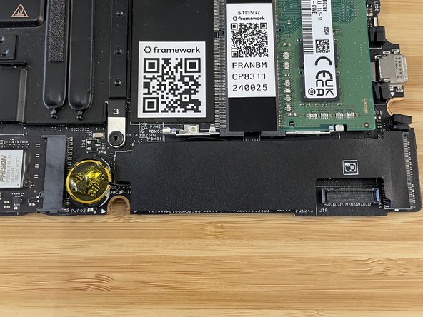
Using a SIM Eject tool or another small pin (such as a paperclip), carefully insert the pin into the hole at the bottom edge of the coin cell receptacle, and tilt it down to eject the coin cell battery. Please use caution here as improper removal can potentially result in damage to the RTC cradle.
-
Safely store or dispose of the coin cell battery at a recycling facility that can handle batteries. Keep coin cell batteries out of reach of children, as there is extreme danger if swallowed.
-
-
-
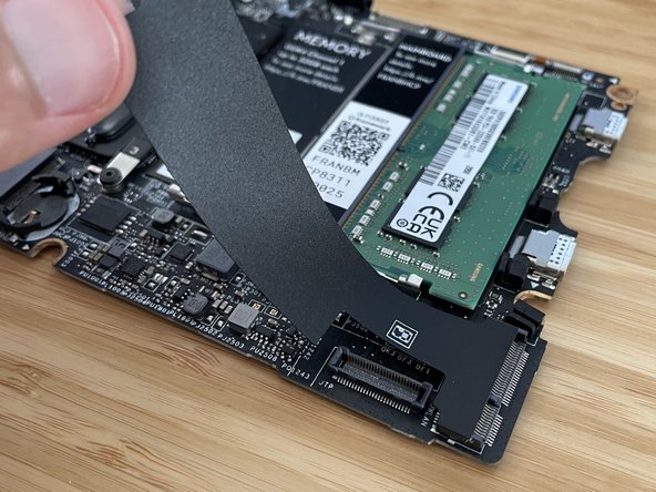
Peel back and remove the black mylar cover that is to the right of the coin cell socket. Set it aside, as you will need to re-use it later.
-
Carefully insert the RTC Battery Substitute into the coin cell socket. Start with the top side, and very carefully push it into place, using the SIM eject tool or pin from earlier to gently tilt the socket open if needed. Note that the socket is fragile, so be extra careful to not use too much force here.
-
Note that on the RTC Battery Substitute, there are two flat spots on the sides where there is no copper present. Make sure those areas are not in the location where they would touch the contact in the coin cell socket, as that would prevent electrical connection. You can check the image to see an orientation that works.
-
Note that you need to keep the clear yellow kapton tape on the RTC Battery Substitute. This is needed to avoid shorting the circuit to the Input Cover above it.
-
-
-
You'll now solder the wire to the 17.6V rail on the Mainboard. Get your soldering iron warmed up, and get some lead-free solder to use. Note that a fine chisel tip is the best shape to use if you have one available for your soldering iron.
-
Bend the wire into place so that it is near the right side of the capacitor that is above the PL331 marking. Don't worry if it touches the smaller capacitor that is above that, as that capacitor is connected to the same circuit.
-
Using your soldering iron and a very small amount of solder, solder the wire onto the right side of the capacitor. Use a magnifying glass or microscope to check that the solder connection is good and that there isn't excess solder bridging to a different area.
-
Once you are sure the wire is good, you can put the black mylar cover back into place.
-


Once you're done, you can follow the instructions in the Mainboard guide starting at Step 17 to put the Mainboard back into the system. Note that since there is no longer a real RTC battery, disconnecting the main battery will result in the clock being reset. When you reboot, the OS will pull the correct time off of a network time server.
Once you're done, you can follow the instructions in the Mainboard guide starting at Step 17 to put the Mainboard back into the system. Note that since there is no longer a real RTC battery, disconnecting the main battery will result in the clock being reset. When you reboot, the OS will pull the correct time off of a network time server.
Cancel: I did not complete this guide.
20 other people completed this guide.
21 Comments
I think I was able to manage this repair. For someone with almost non-existent soldering experience (despite the advice not to try this repair), I think it was not too difficult after looking up some basic soldering tutorials and doing some practices on prototype boards.
However, the caveats are
1. You need good dexterity.
2. The component that you are soldering the module to is much smaller than what the image seems to suggest. Like less than the throughholes of prototype boards. I just eyeballed it, but it would be helpful to also have some alligator clip + magnifying glass setup.
It would've been nice to have Framework do these steps since this issue is somewhat prevalent, but I guess I also gained experience (at a potentially costly risk)
Joo-Hyun Kim - Open Reply
I just did this repair: It's possible to get parts the kapton/isolating tape on top of the "battery side" of the substitution kit wedged into the receptacle - this will make the contact unreliable or break it. Make sure it's not in there and blocks the contact, that happened here first.
Other that that, other than being a little fiddly/scary to install the substitution seems to work fine so far.
Timm Lempfer - Open Reply
I just performed this repair, I think successfully. It was deeply unpleasant. The battery is nerve-wracking to put in, and I find the instructions regarding orientation confusing. There needs to be more photos, of the replacement part itself and which parts of it are exposed. By far the most difficult part is the soldering itself. The wire is extremely small, the capacitor is extremely small. The wire is so small it doesn't want to "tin", get solder on it. I was forced to load my soldering iron with solder, touch the capacitor edge first, then insert the wire into the blob of solder there. To inspect, a magnifying glass is NOT enough. I used a jewlers glasses; ideally you'd have a binocular microscope designed for electronics repair, such that the objective lens remains far from the work so you can solder. Framework should have done this repair in-house at their expense, since it was their design flaw.
Josh Rehman - Open Reply
I would be extremely cautious in undertaking this. The replacement part is not shaped the same around the rim as the battery it is replacing. The replacement has an abrupt 90 degree corner around the cylinder edge on both sides; the battery it is replacing has a rounded edge on the bottom and a recessed edge on the plus side. As a result, while it is relatively easy to slip the battery under the tangs of the plastic clip which holds it in place (both top and bottom), it is much more difficult to fit the replacement part under the prongs of the plastic clip -- the bottom of the cylindrical replacement is wider than the bottom of the battery. The bottom edge of the cylinder doesn't easily fit under the top clip. If it isn't under the prongs at the top, the bottom bracket will break off when you try to snap it in place. I had little trouble replacing the battery; when I went back to replace the battery with the substitute part, I snapped off the bottom bracket. Poor design.
Gary Aitken - Resolved on Release Reply