
Introduction
Here it is, the Framework Keyboard replacement guide! Before you proceed with the keyboard replacement, here is a helpful tip: It is highly recommended that you store each screw in a dedicated space (such as a cup) as you are removing them. It is important to not mix up or lose any screws.
The keyboard is screwed into the Input Cover. The only tool you'll need is your Framework Screwdriver to completely remove the keyboard.
This is one of the few repairs that is time consuming on the Framework Laptop. A quicker but more expensive alternative is to replace the Input Cover which contains the keyboard instead.
Tools
Parts
-
-
Power off the Framework Laptop by navigating to the Windows icon on the bottom left and clicking on "Power" followed by "Shut down," or if on Linux, the equivalent action there.
-
-
-
Unplug your power cable from the USB-C Expansion Card in your Framework Laptop.
(I had formerly left a long comment here about how you guys 'forgot' to have a bit about removing the expansion cards...and while some official guide on this is probably a good idea to have, it's...not actually necessary to remove them! Even though in the build guide, they go in last, they don't actually need to come out in order to replace the screen! Heh.)
-
-
-
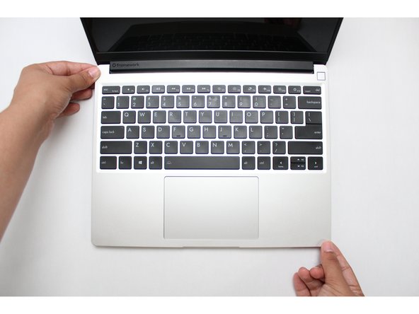
Close the lid on your Framework Laptop and place it upside down on a soft, non-marring surface, such as the bag that it shipped in.
-
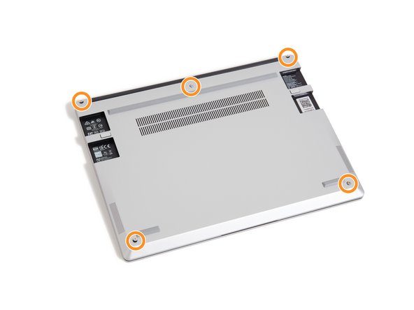
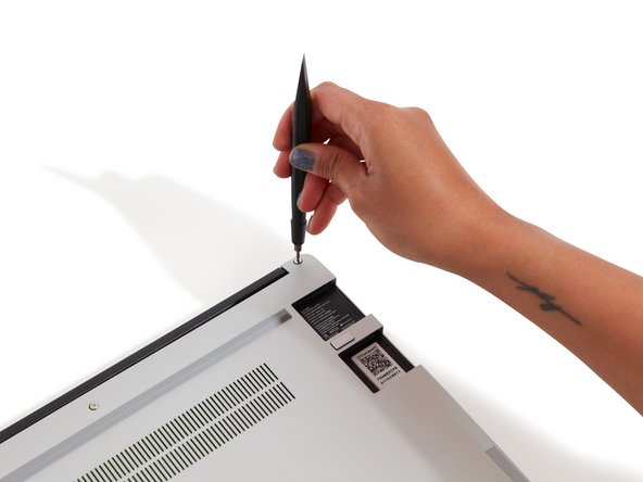
Using the T5 bit in the Framework Screwdriver, unscrew the 5 fasteners on the Bottom Cover. These fasteners will remain attached in the Bottom Cover so that you do not lose them.
-
The fastener on the bottom left (circled in red) will not unscrew as far as the others, as it is acting as a lifter for the Input Cover.
-
You'll hear this fastener start clicking as you rotate when it is unscrewed far enough.
-
Do not use a powered tool for these steps, as this will likely result in damage to the fasteners.
It would be super nice if the lower-left screw were circled in red as the text indicates!
Mike Shaver - Resolved on Release Reply
Thank you for writing the specific detail on the lower left corner screw.
I thought something was not working correct until re-read this guide.
Patrick Corey - Resolved on Release Reply
-
-
-
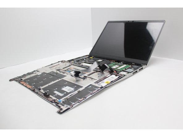
Flip the Framework Laptop back over and open the lid to around 120 degrees.
-
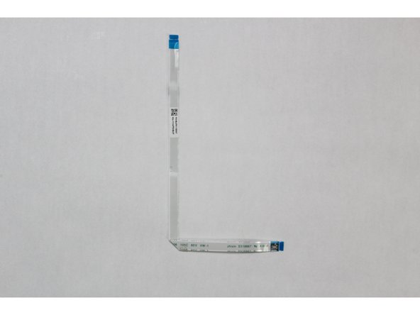
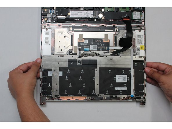
Important: Pull the Input Cover off carefully as it is still attached to the Mainboard via the Touchpad Cable. You don't need to disconnect this cable to do most repairs. You can just flip the Input Cover over. If you do want to disconnect it though, make sure to disconnect the Mainboard side using the finger loop over the orange label.
-
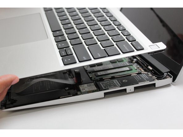
The bottom right corner of the Input Cover lifts up when the five fasteners are properly unscrewed from the previous step. You should not have to use any excessive force to remove the Input Cover.
-
Carefully lift the cover up from the bottom right corner. If you need to, you can use the spudger end of the Framework Screwdriver to lift it as well. Lift the Input Cover off the Mainboard, flip it over (keyboard side down), and place it about halfway on the Bottom Cover.
-
Be sure not to put too much force on the Touchpad Cable when doing this.
-
If the LEDs on the left and right sides of the system are flashing red when you lift off the cover, it means the system is still powered on. Make sure your power cable isn't plugged in and that you have shut down correctly.
-
Note that it may take up to 30 seconds after shutting down for the system to fully power off. Wait until the LEDs stop flashing before proceeding.
-
You should keep the Battery connector plugged in unless you need to replace the Battery, Mainboard, or Speakers. This connector is easy to accidentally damage, so it's better to not handle it.
Important: Pull the Input Cover off carefully as it is still attached to the Mainboard via the Touchpad Cable. You don't need to disconnect this cable to do most repairs. You can just flip the Input Cover over. If you do want to disconnect it though, make sure to disconnect the Mainboard side using the finger loop over the orange label.
While that’s true for most repairs, it’s pretty much essential to disconnect that cable for this repair, so I think the guide should probably amend this boilerplate!
Mike Shaver - Resolved on Release Reply
I can verify that this claim is TRUE, see the "Found out unscrewing stuff on a non-flat surface is a bad idea" section of my recording How NOT to do a Framework Laptop 13 keyboard replacement.
You should flip the keyboard around the x-axis (so that the back edge comes towards you as you flip) and not the z-axis (resulting in the left edge rotating to the right). I started to do the z-axis and the touchpad cable was getting twisted. I am capable of messing up all instructions. This is my anti-super-power... or joker power in the Wild Cards universe.
-
-
-
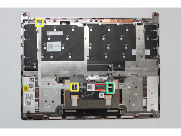
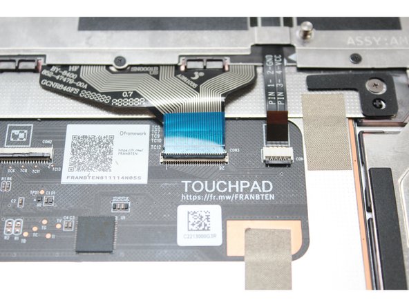
You will be disconnecting the following cables:
-
Fingerprint Cable (from both ends)
-
Keyboard Membrane
-
Keyboard Backlight
-
In this image, the Touchpad Cable is also removed, but we recommend keeping it attached, since there is likely adhesive holding it in place. You'll just need to hold that cable out of the way when accessing the fasteners that are near it.
Please delete previous comment, no idea why it came in and I can't delete it.
Anyway
To remove cables, most of the dark parts open upwards like a door, except the backlight one which should be pulled down. The cables are then loose. No force should be used.
Just adding…
-
-
-
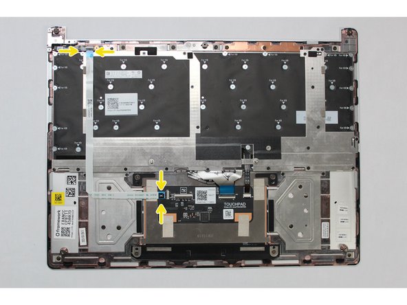
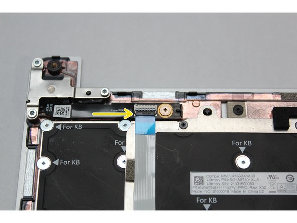
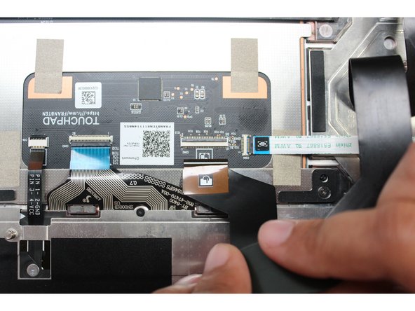
The Fingerprint Cable will be completely disconnected from both ends. Start by disconnecting it from the actual Fingerprint Module.
-
Lift the black latch up using your fingernail or spudger end of the Framework Screwdriver and pull the cable straight out.
-
-
-
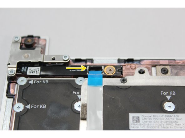
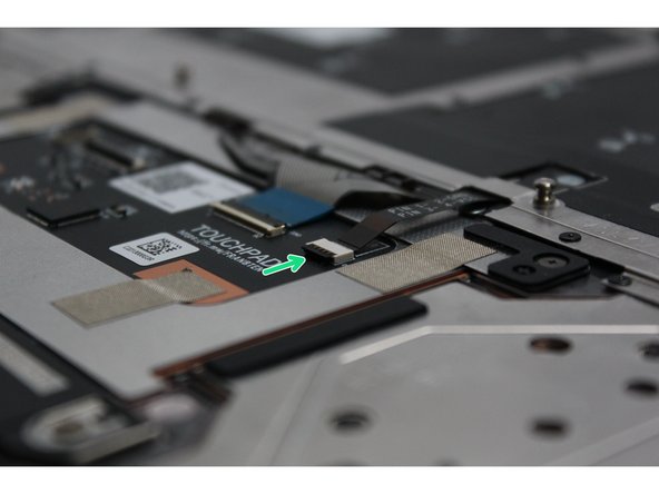
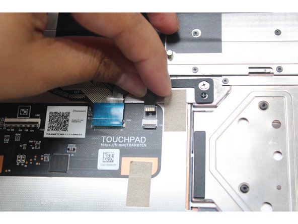
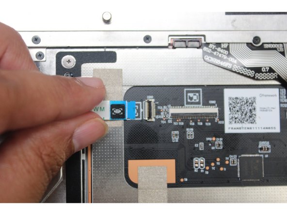
Next, disconnect the Fingerprint Cable from the Touchpad Module. Lift the black latch up using your fingernail or spudger end of the Framework Screwdriver and pull the cable straight out.
-
Use caution when lifting it up the Fingerprint Cable as there is some adhesive holding it to the bracket.
-
Remove the Fingerprint Cable away and keep it in a safe place as you'll need to connect it back when you install the replacement Keyboard.
on my FW the finger print cable was glued in 3 spots. pull on the loose end straight away from the adhesive spot to keep tension on the cable (the tension helps prevent any bending or crimping) and use the spluger end of the fw tool to very gently pry up on the cable to release it from each adhesive spot in turn. keep spluger flat to the board and be gentle to avoid any crimping.
Jim Barron - Open Reply
-
-
-
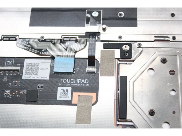
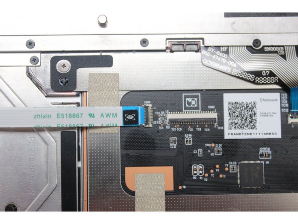
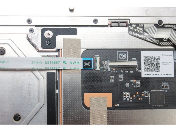
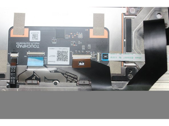
Using the spudger end of the Framework Screwdriver or your fingernail, disconnect the Keyboard Membrane from the Touchpad Module by switching the black latch up and sliding the cable straight out.
The keyboard membrane cable won't go back in straight. Can somebody help me with it?
evannewago - Resolved on Release Reply
-
-
-
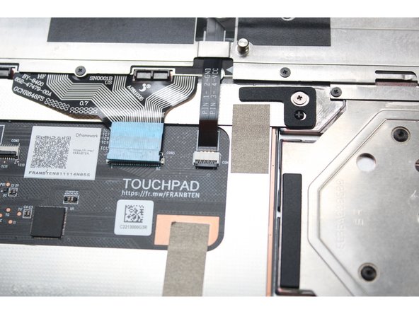
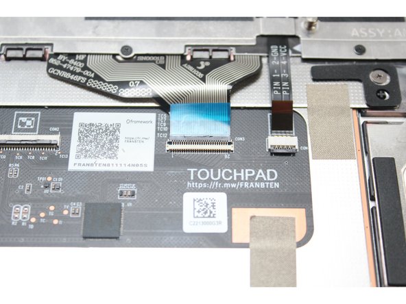
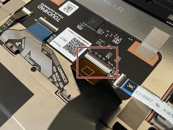
Using the spudger end of the Framework Screwdriver or your fingernail, disconnect the Keyboard Backlight cable from the Touchpad Module by switching the black latch up and sliding the cable straight out.
-
-
-
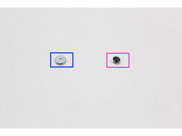
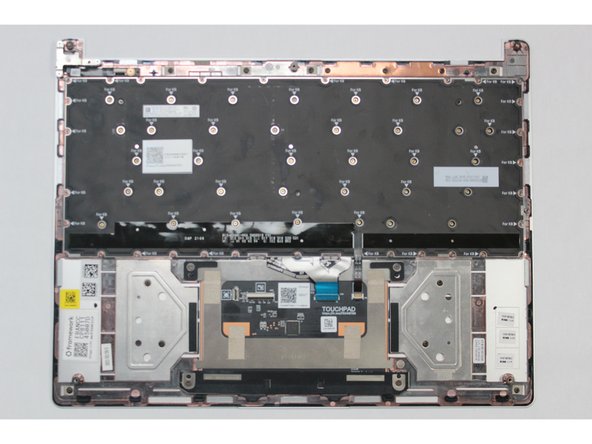
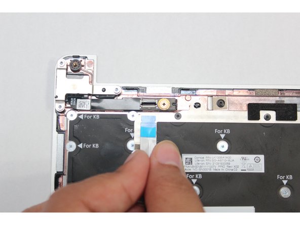
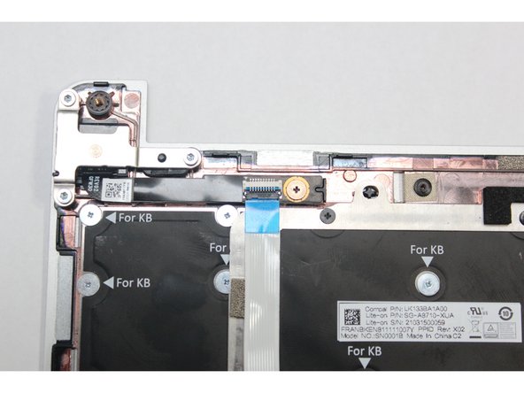
All the necessary cables are now disconnected but before proceeding with removing the fasteners it is important to know the difference between the two types of fasteners you are going to be working with.
-
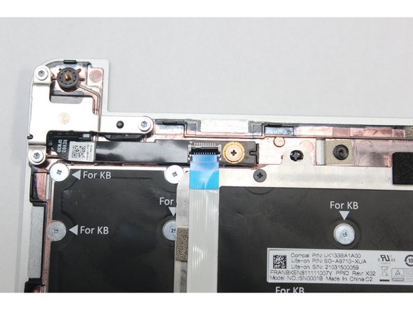
The smaller black fasteners are to be used only on the silver bracket on top of the Keyboard.
-
The larger silver fasteners are used to hold the actual Keyboard in place. You should fasten these only where it reads "For KB."
-
Tip: It is very important to not mix up the two screws together - they are magnetic and very easy to lose. Find a dedicated space for each fastener type. Two small cups would be the best option.
-
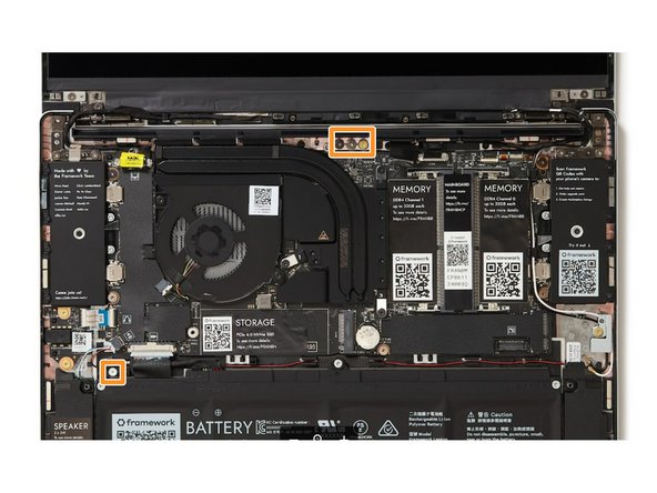
We've included a few spare fasteners that you'll be able to find right in the Bottom Cover as indicated in the second picture.
The following guide shows where the correct spare screws can be located (step 3 for the keyboard screws): Fasteners Guide
There is a spare in the Bottom Cover to the lower left of the battery connector.
Joel Niemelä - Open Reply
-
-
-
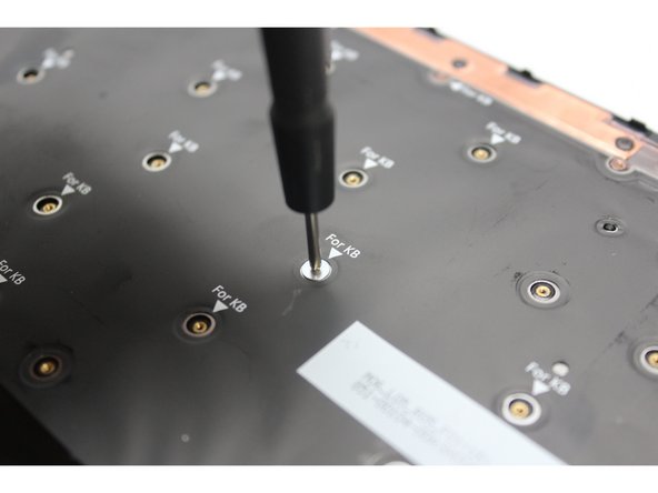
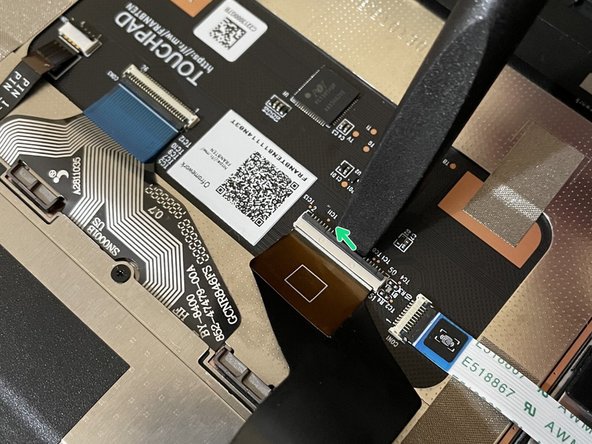
Using the PH0 bit in Framework Screwdriver, unscrew all black fasteners on the silver keyboard bracket.
-
Your Framework Screwdriver has a double-sided bit! One end is the T5 bit, the other end is the PH0 bit. To switch from the T5 bit to the PH0 bit, pull the bit out using your fingers, flip it around, and place it back into the screwdriver!
-
The fasteners are magnetic and very small. To avoid losing them gather them in a dedicated safe space (such as a cup) as you are removing them. Remember to not mix these fasteners with the "For KB" fasteners you are removing next.
-
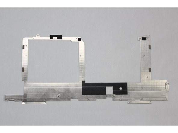
Lift the silver keyboard bracket away from the keyboard bracket.
I wish this step had been started before the cables were detached, because unscrewing the black screws was so obviously MISSION: IMPOSSIBLE that I decided to live with my cosmetic damage and throw out the replacement keyboard.
Julian Fondren - Open Reply
I also stripped a screw, but I was lucky and it was one on the top (in my case the second red circle). That meant that I could just remove the keyboard without fully removing the silver bracket (after unscrewing the keyboard in the next step of course). A bit finicky, but with pressing the keys on the other side possible.
(ignore if using the FW tool)
I used a non FW toolkit. IMHO the "PH0" is a typo. I found that a "PH000" is the size that best fits these very tiny screws.
Jim Barron - Open Reply
I agree with Jim, the proper screwdriver for these screws is PH000, not PH0. Note that it is still possible to strip a screw even when you use the correct tip, be careful and steady when applying forces to the screws!
the image is missing two screws that need to be removed, I marked them in green here: https://imgur.com/a/DHJ7b2T
Nils Lorand - Open Reply
I managed to strip one of the black screws and had to drill it out. Would appreciate guidance/warning about stripping screws. https://imgur.com/a/OqaN6gH
The picture only shows 23 screws to remove, whereas my laptop had 25.
Scott Hayman - Resolved on Release Reply
There's also an extra screw to remove that isn't indicated here (it's actually hidden by a red circle): in the bottom left corner of the photo, just under the fourth screw from the left. See here indicated in blue: https://imgur.com/a/jeeu4SL
Emmanuel Duplay - Resolved on Release Reply
There’s an additional screw to the right of the keyboard screw above the backlight connector (it’s already removed in the first picture)
-
-
-
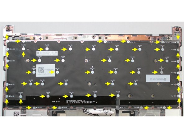
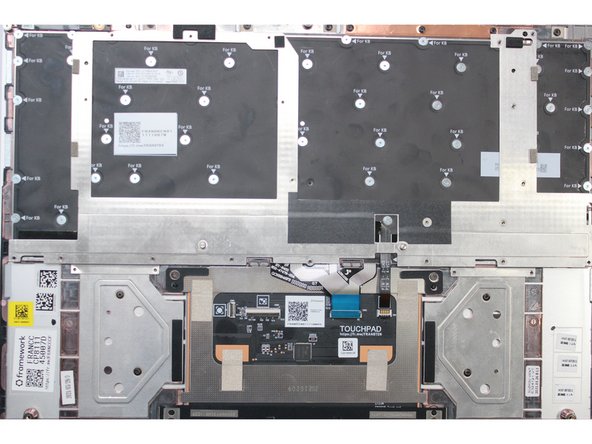
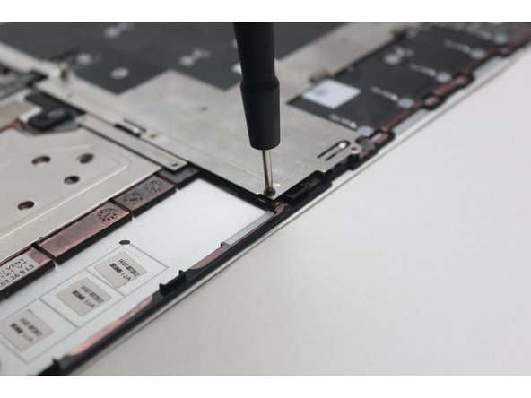
Using the PH0 bit in the Framework Screwdriver, unscrew all "For KB" fasteners holding the keyboard in place.
-
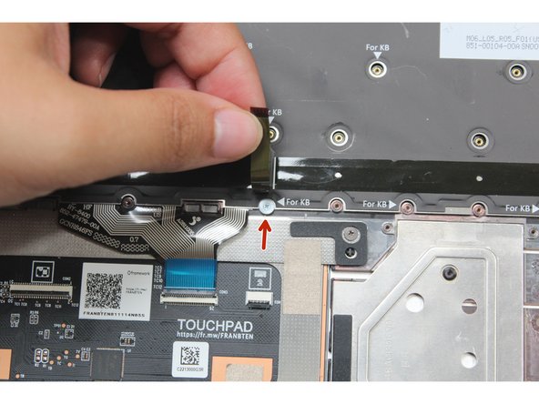
One of the fasteners is hidden under the Keyboard Backlight cable , it must be removed as well. Lift the cable up to expose the fastener and unscrew it. See the second image for more details.
-
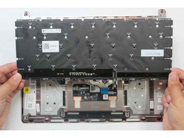
Once all screws are removed use the spudger end of the Framework Screwdriver or your fingernail to lift any corner of the keyboard off the Input Cover. The keyboard is now fully removed from the Input Cover.
again (using non FW tools) I found that PH000 (not PH0) is the size to use here. I suspect that some of those having problems with stripping screws is because they are using a non FW tool with size PH0 (2 sizes too large, guaranteed to strip) instead of the correct size - a PH000 (no tendency to strip at all!)
9
Jim Barron - Open Reply
I agree with Jim, the proper screwdriver for these screws is PH000, not PH0. Note that it is still possible to strip a screw even when you use the correct tip, be careful and steady when applying forces to the screws!
These screws can cam out or strip incredibly easily. I stripped two of them with minimal force. Be careful!
-
-
-
Gently place the new Keyboard into the Input Cover by aligning the edges of the keyboard with the Input Cover as indicated in the first image. The keys should be facing down.
-
Using the PH0 bit in the Framework Screwdriver, screw all the silver fasteners into the slots marked "For KB" that hold the keyboard in place.
-
Do not attempt to screw any fasteners into a slot that is not marked with "For KB."
-
Do not overtighten the fasteners. They are very small and don’t need much force. Only screw in until you feel some resistance.
I agree with Jim, the proper screwdriver for these screws is PH000, not PH0. Note that it is still possible to strip a screw even when you use the correct tip, be careful and steady when applying forces to the screws!
林博仁(Buo-ren, Lin) - Open Reply
again (using non FW tools) I found that PH000 (not PH0) is the size to use here. I suspect that some of those having problems with stripping screws is because they are using a non FW tool with size PH0 (2 sizes too large, guaranteed to strip) instead of the correct size - a PH000 (no tendency to strip at all!)
Jim Barron - Open Reply
I took 43 screws out, but there are 48 "For KB" holes? I'm 100% sure I didn't lose 5 of them
Just did a replacement and I can confirm that the hole and screw count do match.
-
-
-
Once all the silver fasteners are in place on the Keyboard, find the silver bracket and place it over the keyboard by aligning it as indicated in the first image.
-
Screw all the black fasteners into place in the silver bracket.
-
Do not overtighten the fasteners. They are very small and don’t need much force. Only screw in until you feel some resistance.
-
-
-
Connect the Keyboard Backlight Cable into the Touchpad. Make sure the black latch is flipped up so that you can slide the cable into the connector.
-
Make sure to slide the cable in until the white line is almost at the edge of the connector.
-
Flip the black latch down to secure the cable.
-
-
-
Connect the Keyboard Membrane cable into the Touchpad. Make sure the black latch is flipped up so that you can slide the cable into the connector.
-
Slide the cable in until the white line is almost at the edge of the connector.
-
Flip the black latch down to secure the cable.
-
-
-
Connect the Fingerprint Cable into the Fingerprint Module. Make sure the black latch is flipped up so that you can slide the cable into the connector.
-
Slide the cable in until the white line is almost at the edge of the connector.
-
Flip the black latch down to secure the cable.
-
-
-
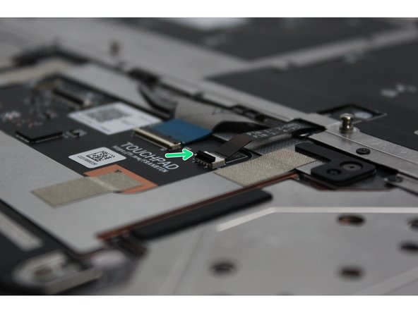
Connect the other end of the Fingerprint Cable into the Touchpad Module. Make sure the black latch is flipped up so that you can slide the cable into the connector.
-
Slide the cable in until the white line is almost at the edge of the connector.
-
Flip the black latch down to secure the cable.
-
-
-
Place the Input Cover on the Bottom Cover Keyboard Side down as indicated in the first Image.
-
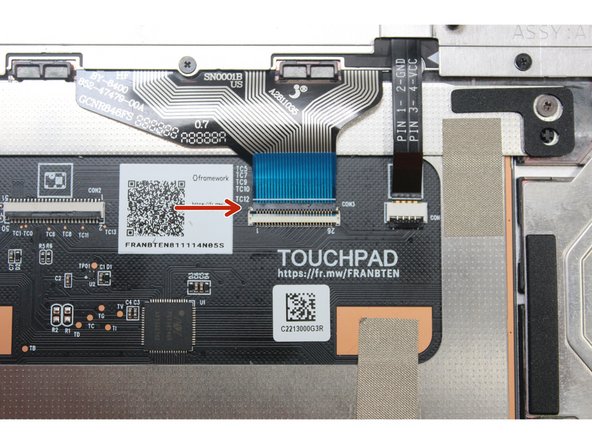
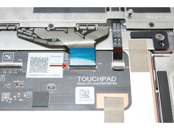
Connect the Touchpad Cable. Make sure the black latch is flipped up so that you can slide the cable into the connector.
-
Slide the cable in until the white line is almost at the edge of the connector.
-
Flip the black latch down to secure the cable.
-
-
-
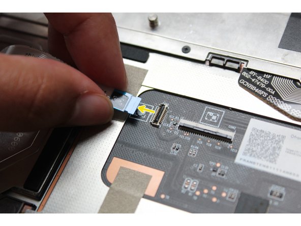
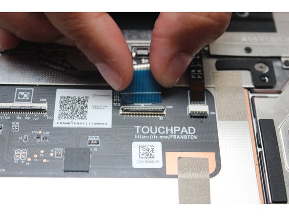
Before closing up the laptop, make sure that the Touchpad end of the Touchpad Cable is fully seated in the receptacle.
-
The cable should be inserted far enough that the white line almost touches the receptacle.
-
If it is not inserted far enough, you'll need to flip up the black latch on the other side of the connector, slide the cable in further, and then close the black latch again.
-
-
-
Flip the Input Cover over the Bottom Cover so that the keyboard is facing up and attach it to the Bottom Cover by aligning the top and bottom edges of both covers.
-
Tip: The covers are magnetic and should fit into one another easily. If you feel any resistance simply lift the Input Cover up and try again.
-
-
-
Close the Framework Laptop and turn it upside down to reveal the five fasteners on the Bottom Cover.
-
Using the T5 bit in the Framework Screwdriver, screw all 5 fasteners back into the Bottom Cover.
-
Be sure to not over-tighten the fasteners.
-


- To purchase a Framework Laptop visit the Framework website
- Want to learn more about the Framework Laptop? Take a look at our blog
- If you have any questions or concerns, feel free to reach out to Framework Support
- To purchase a Framework Laptop visit the Framework website
- Want to learn more about the Framework Laptop? Take a look at our blog
- If you have any questions or concerns, feel free to reach out to Framework Support
Cancel: I did not complete this guide.
36 other people completed this guide.
24 Comments
Is this the same for the framework 17? I'm confused by all these steps, since I thought the 17 just popped the keyboard out?
Dan Ginovker - Open Reply
I just performed this on a Ryzen AI 300. It was fairly straight forward. There was one screw that was stripped out from framework and it was on the outer most edge of the keyboard. I was able to slide the keyboard out and install the new one. I found out my Control keys no longer register (left or right) I double checked the connections 3 times and even ended up cleaning the connections with 99% isopropyl and still the Ctrl keys do not work. Not sure what to do from here.
Jason Mangano - Open Reply
Successfully performed on the Framework 13. Three of the silverhead screws were stripped, so I used a power drill to extract them. Currently using the laptop without the missing screws, both the keyboard and laptop are functioning perfectly.
On that note, I’d recommend Framework consider using stronger screws if possible. I’m pretty new to DIY, so I’m not sure how feasible that might be, but it could help avoid issues like this for beginners.
Ashfaque Ahbab - Open Reply
Did this over the course of about an hour, found out that the keyboard fastener underneath the backlight cable was partially stripped (of course it's the one right under an unremovable cable lol). Ended up having to remove the touchpad cable and put the input cover on a flat surface to get the right pressure to get the screw out. Go slow if you have to remove the touchpad cable, there's a good amount of adhesive under it that will release bit by bit with steady pressure.
aye used the gu-aye-d to replace the cuh-eyboard my laptop already had w/ a lat-eh-n amer-eh-can cuh-eyboard. comma. aye was able to swap them well and hadn´t seen any problems when aye was reasembl-eng the computor. However now that aye am actually test-eng eh-t out theres a couple cuh-eys {cuh-ees. the ones you press to type letters and stuff} that won´t reg-eh-ster no matter what aye do.
the cuh-eys {cuh-ees} that don´t funct-eh-on are:
8 , i k {the lower br-y-tness cuh-ee} ******or any of there sh-eh-ft or alt cuh-ey {cuh-ee} forms
anybody no any decent remedys for th-eh-s?
{no eh-ts not just me not be-eng used to the layout. aye have attempted eh-t w/ the cuh-eyboard sett-eng set to standard US just to see try and they also don´t wor-cuh} {also have fun read-eng th-ehs lol. and than-cuh you eh-ff you can help}
crystal clear - Open Reply
Performed successfully on the AMD Ryzen AI 300 model's input cover (wanted to re-align the keys as the up arrow was sometimes brushing against the aluminum frame when pressing).
I used iFixit equipment and used the Phillips 000 bit for the black bracket screws, and the Phillips 00 bit for the steel keyboard screws. Only minimal cam-out issues on the bracket screws, otherwise felt pretty safe the entire time.
Yonsung Lee - Open Reply
I'd mirror other comments in that this isn't very difficult but it is incredibly tedious. There's a hell of a lot of tiny screws to keep track of.
From start to end it was around an hour.
Personally I didn't fully remove the fingerprint reader cable. I just disconnected one end and carefully moved it out of the way when needed.
Andrew Herzog - Open Reply
It took me about 2 hours to complete. I now have a brand new clear keyboard installed, after having a broken down button.
The KB screws took a while for me to remove and install.
One of the KB screws had been stripped when the laptop was assembled, I assume. It took a little while to remove, and then I had to decide what to do for installation. I left the bad screw out for now, and will get another screw soon. Installing a single screw should be quick.
Another one of the KB screws hit my table and then disappeared. Since it is magnetic, it attached itself to the underside of the laptop, and took me much too long to find it. First, I searched for it elsewhere, and finally found the missing screw when I nearing the end.
I had trouble determining how to lift the black latches for the cables. Once I lifted the first one, the others were easier.
I attached some TESA tape to the fingerprint sensor, since it had previously had tape which was no longer sticky. It probably isn't necessary, but nice to have.
Kevin Dalley - Resolved on Release Reply
One more thought.
I wish I had cleaned the input cover when I had the keyboard removed. That would be the perfect time to remove the grime from the cover. Now that the new keyboard is in place, the grime is more obvious than it was with the old keyboard, also grimy.
Completed in about 45 minutes. Step 11 is missing a couple red circles on screws that need to be removed, but it was easy enough to figure out.
Nathan Michalik - Resolved on Release Reply
I would love to see a guide for printing custom layouts on the blank keycaps for the keyboard variations (blank & transparent that are available for DIY editions), I am sure a good number of FOSS fans, Linux/BSD users would be willing to pay to print their own custom layouts.. Tuxedo computers offer this to their customers.
Toufiq Khan Majlis - Resolved on Release Reply
Keyshorts will print stickers, and there is a Frameworks option.
If i make a mistake, such as stripping a screw-hole, is it likely that my pc won’t work at all?, till i obtain & install a new Input Cover (which contains a new keyboard). Thanks in advance for any comments.
The first time I swapped the keyboard, I did break the screw hole on two of the screws (one black one and one silver one) near my tab key and the volume up/down keys over a year ago. I use them often and have had no noticeable difference. The amount of increased flex is low enough that I cannot notice it, and no components of the keyboard that carry electronics touch the underlying components even if you were missing many more screws from what I can tell.
Wolf T -
Here is a summary of the answer i recently received from Framework support:
- It’s ‘quite difficult to answer ... .’
- If you injure one screw hole, then ‘there's at least a 10% chance that the laptop will not be useable ... .’
- ‘if you dismantle the keyboard from the input cover and unscrew the keyboard membrane - then there is a high chance that random[ly] several keys might stop working[,] ... and [a moderate chance that] 80% to 90% of the keyboard keys might stop working ... .’
- ‘alternatively, you can still use an external USB keyboard/mouse.’ (But that’s burdensome to me.)
- Or you can install a new Input Cover, containing a new keyboard.
Doug H -
Answer from a novice: No. None of these screws are electrically connected to the computer. These are all mechanical fasteners. A single missing screw will, likely, only create additional flex in the typing deck. It may be annoying, but won't impact the function of the computer.
There is an inaccuracy in this guide. The photo in Step 11 is incorrect: there are two screws that aren't circled. I've circled the two additional screws in bright green here.
In addition, the claimed "Time Required" of "00:15:00 - 00:30:00" is inaccurate and should read "00:30:00 - 00:45:00".
Please consider fixing the guide. Thanks!
Nadim Kobeissi - Resolved on Release Reply
Having done this now 3 times, because I can't decide on a layout, I absolutely agree this is NOT a 00:15:00 - 00:30:00, but at least 30 minutes. I clocked myself at 42 minutes on my most recent keyboard swap, and that is with prior experience. Screwing and unscrewing 75+ screws with precision is not a 20 minute job. You will be hunting for where the last one or two screws come out for at least a few minutes, and then again where the last few go. I can guarantee no first time Framework keyboard swapper is doing this in under 45 minutes.
I would say this procedure is not difficult, it just takes time.
Wolf T -
Especially with a task as involved as this, create a clear, uncluttered workspace (where things can’t be easily misplaced); allow plenty of time (so you’re not rushing); try to ensure you’re not disturbed (to keep concentration); make sure you have good lighting; if you need to, make notes/sketches as you go (don’t trust to memory) - and work methodically.
Steve Burgess - Resolved on Release Reply
songbI’ve replaced my framework laptop’s keyboard by following this guide. Note that on step 11, in addition to the screws labeled in the picture, you should unscrew one more screw so that you can remove the silver bracket.
Expect 40 minutes to one hour to replace the keyboard, as there are really many tiny screws and you may accidentally lose one of them (for the screws fixing the silver bracket I’ve found no spare ones fixed in the bottom cover). I almost lost one when I did it!
I agree with Shirley — this is not “difficult“. There are no risks if you know how to connect and disconnect the cables, and screw and unscrew the fasteners. But it is repetitive, time-consuming, and tiresome for myself.
Songbo Wang - Resolved on Release Reply
I wouldn’t call this procedure difficult. I’ve worked on a lot of laptops; this one is only moderate by the overall standards of laptops, though it is likely the most difficult repair to do on a Framework.
What it IS, though , is tedious. There are a LOT of tiny screws to remove and replace. It took me most of an hour to do this repair; the estimate of 15-30 minutes is likely a considerable underestimate.
If you’re paying somebody else to fix your Framework, don’t do this one. Spend the extra money to buy an entire Input Cover. That’s a much faster repair so you will spend less money in total.
Shirley Dulcey - Resolved on Release Reply
Yeah, I don't have mine (yet), but looking at it, this is a lot easier, though the one company that seems to be easier is the elitebook series from HP, where it's 2 screws and a few clips.
If you are upgrading to an Intel Ultra series, disable Bitlocker before shutting down your old main board if you are upgrading to an Intel Ultra series.
And for Ultra series, install windows as a fresh installation. This appears to be particularly important if you can't disable Bitlocker because your old main board died.
Jim Barron - Open Reply
Before even starting, inspect the new board to be sure all the connectors are ok. Mine had the speaker connector broken off.
Gary Aitken - Resolved on Release Reply
@ahappykittycat I wish that I had read your comment before I undertook this…
Mike Shaver - Resolved on Release Reply
IMPORTANT: If you plan to install your existing mainboard in a CoolerMaster case, make sure to boot into the BIOS and enable standalone mode before continuing.
Richard Tango-Lowy - Resolved on Release Reply
Pretty sure you might want to include a reminder to backup the bitlocker recovery key if it is enabled. The system will definitely boot to the bitlocker recovery screen since it will be a different TPM.
James Wu - Resolved on Release Reply
It could be helpful to give the bash terminal command to shutdown such as
Patrick Corey - Resolved on Release Reply
Bottom left*
Vijfhoek - Resolved on Release Reply