
Introduction
How exciting, you got your hands on a Framework Laptop 13 DIY Edition! This guide will walk you through each step from unboxing to powering on your laptop so you can start using it right away. As with all of our guides, make sure you read the directions in each step and view each image first.
After finishing the Quick Start Guide, if you’re installing Windows, check out our Windows 11 Installation Guide and don’t forget to install the Framework Laptop Driver Bundle. You can also check out our Linux compatibility page for the distros that work great on the Framework Laptop.
If you have questions or run into any issues, check out the Support pages.
Note: If you have a 13th Gen Intel Core system, you should follow this newer guide, and if you have an AMD Ryzen 7040 Series system, you should follow this guide.
Tools
Parts
No parts specified.
-
-
Unbox your Framework Laptop. Don't power it on just yet, since you'll need to install some modules first.
-
-
-
Locate the Framework Screwdriver in the package underneath the Framework Laptop and keep it handy - it's the only tool you'll need to assemble the Framework Laptop DIY Edition.
-
-
-
Depending on how you customized the configuration, your package may include a combination of memory, storage, a WiFi card, and a mix of Expansion Cards. You can find all of your modules in the accessory box or bag in your shipment.
-
Unpack all of these modules so that you are ready for your install!
-
-
-
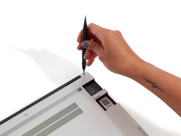
The fastener on the bottom left (circled in orange) won't unscrew as far as the others, as it is acting as a lifter for the Input Cover. You'll hear it start clicking as you rotate when it is unscrewed far enough.
-
Using the T5 bit in the Framework Screwdriver, unscrew the 5 fasteners on the Bottom Cover. These fasteners will remain attached in the Bottom Cover so that you don't lose them.
-
Turn the Framework Laptop over and open it to 120 degrees.
-
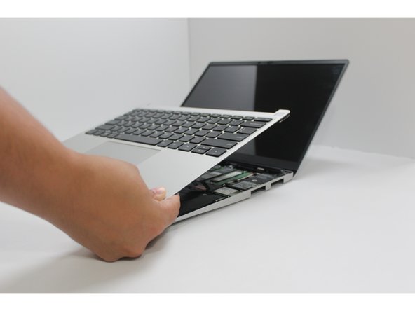
Important: Do not pull off the Input Cover too fast as it is still attached to the Mainboard by the Touchpad Cable.
-
You don't need to disconnect the Touchpad Cable to do most repairs. You can just flip the Input Cover over. If you do want to disconnect it though, make sure to disconnect the Mainboard side using the finger loop over the orange label, while keeping the Touchpad side connected.
-
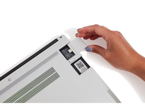
The bottom right corner of the Input Cover lifts up when the five fasteners are properly unscrewed. You should not have to use excessive force to remove the Input Cover.
-
Carefully lift the Input Cover up from the bottom right corner. If you need to, you can use the spudger end of the Framework Screwdriver to lift it as well. Lift the Input Cover off the Mainboard and flip it over (keyboard side down) and place it about halfway on the Bottom Cover.
-
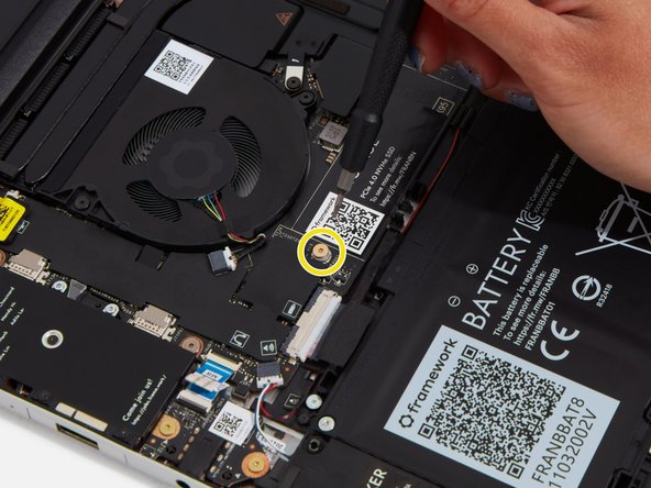
You should keep the Battery connector plugged in unless you need to replace the Battery, Mainboard, or Speakers. This connector is easy to accidentally damage, so it's better to not handle it.
One of the small ferrous metal strips was loose when I first opened the cover. It seems like just glue failure. Can I use CA glue to reattach it, or should I use something else?
Neal Tibrewala - Resolved on Release Reply
My DIY i5 was shipped with the battery physically disconnected. Wasn’t easy to find the solution since the status light lit up and the power button lit up briefly, but it wouldn’t boot.
Yes, my DIY i5 battery wasn’t plugged in either. The DIY Guide needs to be amended to *add* that step for people who aren’t familiar with hardware.
JB FW -
Note: the battery might be disconnected for transport. The first step should probably be to plug in the battery into the laptop. See Battery Replacement Guide
Kelly Fennig - Resolved on Release Reply
Hi Kelly, we ship with the battery connected, but in a safe “shipping mode”. Plugging in a power cable near the end of this guide takes the battery out of shipping mode.
-
-
-
Get ready to install the Storage module by removing the fastener for it from the Mainboard using the T5 bit in your Framework Screwdriver.
-
Align the notch on the Storage module with the notch on the socket and slide the module into the Mainboard at a 20 degree angle.
-
Using one finger, gently hold the Storage module down to the Mainboard and use your other hand to screw in the fastener using the T5 bit in the Framework Screwdriver.
-
Be sure to not over-tighten the fastener.
I have the same problem as Andri above. The T5 fastener notches came rounded and I couldn't unscrew it. I tried with both Philips and flat head and no bueno. This means I can't install the SSD. I've sent a support ticket, slightly disappointed after such excitement when getting my hands on it.
The T5 fastener looked like the notches weren't quite as pronounced as the others--might have been a one-time manufacturing issue that only I got. In my case, though, the provided T5 screwdriver was unable to get a grip and I couldn't unscrew it. Luckily, I had tiny Philips-head on hand and that worked.
Andri Braun - Resolved on Release Reply
Mine actually came without an existing storage screw, so I was left wondering, is this hole I’m putting the screw driver into a screw? Oh no, it must be the socket. How do you expect the SDD to be fixed with no screw?
kim carter - Resolved on Release Reply
Could you reach out to Support: https://frame.work/support#contact_suppo...
There is also a spare fastener for the SSD in the Laptop: Fasteners Guide
If the metal pins are still visible on the storage, it’s not all the way in. There’s some friction, so I very slightly wiggled it to slide it in.
This video was helpful: https://m.youtube.com/watch?v=NCIqZjo34r...
David Percy - Resolved on Release Reply
I can’t see any headsink for the nvme drive. Couldn’t a missing heatsink result in an overheated and throttled nvme drive? Especially pcie 4.0 nvme drives tend to become quite hot under load. Any test made e.g. with the WD-SN850?
Markus Menzel - Resolved on Release Reply
Some nvme drives will get thermal-throttled even if there’s a heatsink, as the laptop chassis is tight and limits the amount of airflow. That’s why one should look for what the big OEMs used in their laptops when considering upgrades. As for SN850, I didn’t see any test results, but I guess it should be fine. After all, Framework provides the option to use SN850 in the DIY version. I think they have already confirmed the stability of SN850.
Mike Yin -
Clarifying for those like myself that have never installed storage before.
You do slide the storage in at a 20 degree angle, but the storage *stays* at that angle when fully inserted. I assumed it become parallel when inserted, but it only becomes flat in step three as you press it down with your finger.
This video (at timestamp) cleared things up. https://youtu.be/eBO8r2CgnxQ?t=106
Michael Ward - Resolved on Release Reply
-
-
-
Insert the Memory module into the Mainboard at around a 25 degree angle, aligning the notch on the Memory module with the notch on the socket.
-
Once the module is fully inserted, it will sit at a 25 degree angle. Gently press it down towards the Mainboard until the clips located at the top and bottom of the receptacle snap into place (see the red arrows in the second image).
-
If you are using one Memory module, place it in the right socket that is labelled “Channel 0."
-
The first boot after installing a new Memory module will take longer than normal, as the system prepares itself for the new module.
There is now only one image, which isn't good -- the image showing is for channel 1, and should be for channel 0.
Gary Aitken - Resolved on Release Reply
The black bracket that holds the black and white wires became unglued while inserting channel 0 RAM. What adhesive to you recommend?
Thomas Hickey - Resolved on Release Reply
Just added a second 32gb memory module and it has been powered up for 20 minutes but still has not booted. No display, nothing. How long should it take? How do I know if the memory module is defective or there is some other problem?
Hi Richard, please reach out to our support team for help on this: https://frame.work/support#contact_suppo...
Note: If you are using two Memory modules, place one
upside down in the left socket, labelled “Channel 1,” so that the notch
on it aligns with the notch on the socket.
Steve Kleiman - Resolved on Release Reply
second image, not the third image. (there are only two images.)
Jim Garrison - Resolved on Release Reply
-
-
-
If your WiFi module came pre-installed, lucky you! You can skip over the WiFi steps, but don't forget to install the Driver Bundle when you're done setting up.
-
Unscrew the fastener using the T5 bit in your Framework Screwdriver, and remove and save the silver-colored WiFi Bracket that is holding down the cables.
-
Remove the clear plastic covers from the antenna cables, and carefully connect the black and white WiFi antenna cables into their respective sockets on the module. Make sure to align them well before applying force to click them into place, as the connectors are small and fragile.
-
If you need a video overview on this, check this out.
-
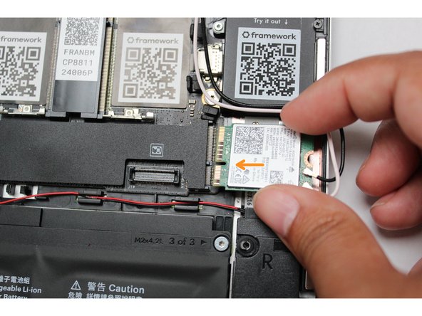
Once both the black and white WiFi Antenna cables are connected to the module, make sure they are rotated downwards as indicated in the second picture with the blue arrows.
-
While keeping a finger on top of the antennas to hold them in place, insert the WiFi module into the socket on the Mainboard.
I just watched a Dell technician replace a motherboard on an XPS-13. He had the same problems as others on this forum of getting WiFi antenna wires hooked up to an Intel WiFi microboard. It took him a couple of minutes of fiddling, changing the position of the connector slightly then pressing, then shifting the connector again and trying again when it didn’t snap. He says that he has had to keep one fingernail untrimmed so that he can use it to press down on the connectors! If the connector doesn’t snap on, keep trying until it does.
Bruce Dunn - Resolved on Release Reply
For some people, it may be helpful to put on a pair of reading glasses so that they can see the tiny parts easily. Antenna wires come with a clear plastic sleeve over the connector and about 1 cm of the wire - these slide off with a gentle pull. Then pinch each antenna wire a couple of cm from the connector, then pinch the connector and twist until the flat side of the connector is in the same plane as the module. You can attach the wires using your fingers to pinch the connector down on the module, or place the module flat on the surface of one of the tiny cardboard boxes used for USB modules and press the antenna connector down. When the connectors are aligned and pressed, they will snap onto the module. It may take repeated tries to get the connectors aligned just right so that they snap when pressed. Before placing the bracket in place, get the needed screw ready by sticking it on the end of the magnetic screwdriver so you can insert the screw one-handed.
Bruce Dunn - Resolved on Release Reply
It seems important to have enough bend in the black and white wires so the wires are straight enough to stay in the wire guides near the memory modules.
Douglas Rice - Resolved on Release Reply
Took me about 40 minutes to install just the wi-fi module. Don’t feel bad and don’t give up if you’re the same.
Cameron Salomone - Resolved on Release Reply
WiFi module did not have the cable guide shown in the second image near the index finger. However, it does not appear to be required.
Robert Chatters - Resolved on Release Reply
Good luck, unable to get one ant wire to stay clipped on long enough to get installed and do not think it would stay on later, anyway. May have to use glue to keep it in place.
Ed Quartemont - Resolved on Release Reply
Hi Ed, just clarifying, the WiFi Bracket that is placed on top of the card and antennas will keep the antennas securely attached.
The video is pretty essential. Otherwise I would not have known what to do with the bracket and screw.
Jim Garrison - Resolved on Release Reply
-
-
-
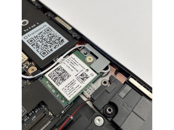
Once the module is properly inserted into the Mainboard, carefully route both the black and white WiFi Antenna cables into the black rubber holders as indicated in the first image. Route both of the cables through the channel located near the top right of the WiFi module as well.
-
It's ok for the metal parts of the antenna cables to touch each other and touch the WiFi Bracket. These are all part of a common ground path.
-
The antenna cables should not touch the Speaker located below. Use the spudger end of the Framework Screwdriver to carefully push the white cable away from the Speaker if it is touching it.
-
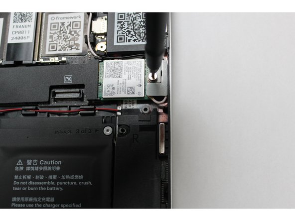
Place the WiFi Bracket over the WiFi module, matching the orientation that is shown in the image, and place the fastener in the hole. Using the T5 bit in the Framework Screwdriver, screw the fastener into place.
-
Be sure to not over-tighten the fastener.
-
Don't forget to install the Driver Bundle at the end if you're using Windows! WiFi may not work until you do that.
As others mention, this is the one part of the installation that is tricky. Remember the instruction “Make sure to align them well before applying force to click them into place,” and have faith that the wire will in fact connect to the board with an audible click. It helped me to have a bright light and reading glasses to align. Applying the force might be tough if, like me, you have no real fingernails and soft fingers! Pressing down only squished the cable end into my finger. I actually ended up holding each cable in place with one hand and using the back of a fingernail from the other hand to press firmly until I heard the click. Then I kept on holding them in place until the bracket was in place (maybe unnecessary but I didn’t trust the assembly). Wifi works fine!
Note: The connectors have two parts, a loop and a solid
part; make sure that the loop is positioned below the solid part.
Steve Kleiman - Resolved on Release Reply
The cables were slightly too long to make this easy. I found the use of non-metal tipped tweezers made it significantly easier.
ben@lee-cohen.com - Resolved on Release Reply
-
-
-
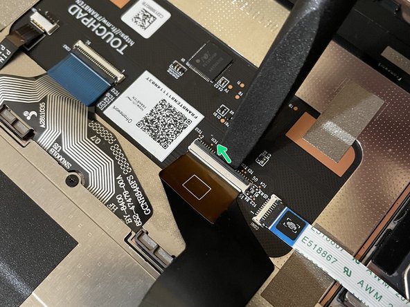
Before closing up the laptop, make sure that the Touchpad end of the Touchpad Cable is fully seated in the receptacle on the underside of the Touchpad.
-
If your Framework Laptop came with an envelope with instructions around adding tape to the Touchpad Cable, you can follow the Touchpad Cable Fix Guide now to add the tape to keep the cable in place.
-
If your Touchpad Cable already has double sided tape holding it in place on the Touchpad, you're all set!
-
The cable should be inserted far enough that the white line almost touches the receptacle.
-
If it is not inserted far enough, you'll need to flip up the black latch on the other side of the connector, slide the cable in further, and then close the black latch again.
If you've disconnected your keyboard, remember to plug it back in.
Mark MacDonnell - Resolved on Release Reply
Note: If your Touchpad comes taped onto the frame and
your Laptop package includes a sealed envelope containing a sticker with
information about a Touchpad Cable Fix Kit, your Touchpad has already
been fixed and there's no need to take further action to secure it.
Steve Kleiman - Resolved on Release Reply
-
-
-
Flip the Input Cover over the Bottom Cover so that the keyboard is facing up and attach it to the Bottom Cover by aligning the top and bottom edges of both covers.
-
The covers are magnetic and should fit into one another easily. If you feel any resistance simply lift the Input Cover up and try again.
If you're wondering "The left side snaps together nicely but there's a huge gap on the right side! Did I do something wrong? Will I break something if I ignore it and screw everything back together??" the answer is probably no, since the captive screw is supposed to push the whole thing upwards a bit. (Check out the photos in that thread, and if you're still in doubt, reach out to the fine folks at Framework.)
-
-
-
Close the Framework Laptop and turn it upside down to reveal the empty Expansion Card bays and fasteners on the Bottom Cover.
-
Using the T5 bit in the Framework Screwdriver, screw all 5 fasteners back in.
-
Be sure to not over-tighten the fasteners.
-
-
-
Insert the Expansion Cards of your choice into any of the empty bays.
-
The text, logo, and QR code on the Expansion Card must be facing down (facing the laptop). Slide the Expansion card into the bay. Using two or more fingers push the card until into the bay until it clicks.
-
You will have to use a slight amount of force to ensure proper installation of the Expansion Cards.
-
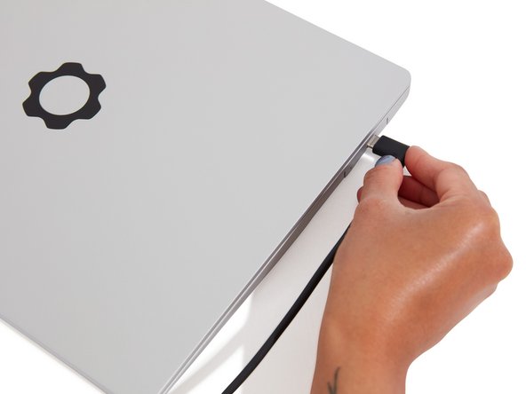
Plug your power cable into the USB-C Expansion Card.
-
Open the lid on your Framework Laptop and press the power button.
-
Note that your first boot will take a while before the logo comes up on screen as the system does memory training. The more memory you've installed, the longer this could take (on the order of a minute or two with 64GB!)
I had the Ethernet module and a USB key inserted in the USB A module on first boot of my 11th Gen DIY factory seconds unit, and I had no logo or image on the screen. I removed both and was then able to get a "no boot device" error from the BIOS, which is what I expected. Just FYI.
David Mathias - Resolved on Release Reply
my computer still hasn't booted up and it's been 6 hours...what should i do?
Andie Manning - Resolved on Release Reply
Note that the cable between the power supply and the computer is USB-C on each end, but one end has the wire at right angles to the connector, while the other has the wire going straight into the connector. If your power supply wire goes to the back of your desktop, it is preferable to use the right-angle connector on your computer. If your wire goes to the right or left, use the straight-in connector.
Bruce Dunn - Resolved on Release Reply
-
-
-
Find the instructions for installing Windows 11 here.
-
Don't forget to install the Driver Bundle!
-
The Framework Laptop is designed to work great with Linux too. Check out our Linux compatibility page for distros we recommend, like:
-
Fedora 38 - Essentially fully functional out of the box.
-
Ubuntu 22.04 - Essentially fully functional out of the box.
-
On both Windows and Linux, we recommend updating to the latest BIOS available to make sure the laptop is running at optimal performance and stability.
11th Gen should support Windows 10. However, using newly-created Media Creation Tool-generated USB file, no storage driver is present in the media. This is going to be a problem.
David Mathias - Resolved on Release Reply
You ppl at Framework hv been doing great.......But, we kindly request framework team to consider shipping to CHINA ...????
Whatz stopping you guys to ship to China..???
maharshiharish - Resolved on Release Reply
I strongly recommend that everyone should fully test their memory before installing an operating system. Download and install the free version of Memtest86 to a USB drive and boot that and let it run until completion: https://www.memtest86.com/download.htm
NB: You need to go into the Memtest86 settings and manually set the screen resolution to the highest on the list for the test progress screen to be visible.
Yes, you’re all excited to start using it I know! :-) , however, unreliable memory may corrupt your operating system install and corrupt your files as well as lead to crashes. It’s best to assume that your memory is unreliable until proven otherwise.
Emmanuel Galanos - Resolved on Release Reply
More Linux info is now at https://frame.work/blog/linux-on-the-fra...
Jim Garrison - Resolved on Release Reply
I can help with the linux guide? like linux mint (What i love and its user-frienly)
Alejandro Alzate - Resolved on Release Reply
Hi Alejandro, for now the best place to provide Linux guidance is in the Community subforum: https://community.frame.work/c/diy-editi...
We’ll start to grab some of the information from there for creating new guides.
-


- To purchase a Framework Laptop visit the Framework website
- Want to learn more about the Framework Laptop? Take a look at our blog
- If you have any questions or concerns, feel free to reach out to Framework Support
- To purchase a Framework Laptop visit the Framework website
- Want to learn more about the Framework Laptop? Take a look at our blog
- If you have any questions or concerns, feel free to reach out to Framework Support
Cancel: I did not complete this guide.
115 other people completed this guide.
26 Comments
In reference to my earlier comment, I think this is the resource I was looking for. Could I humbly encourage Framework to consider adding a link to this Quick Start guide?
David Mathias - Resolved on Release Reply
While links to driver bundles and BIOS are helpful, I was hoping there would also be a link to a walkthrough of the BIOS features, settings and recommendations for configuration - perhaps for Win and non-Win operating systems. I presume I'll need to dig around in Support or Community now for this information. My DIY seconds laptop shows up this morning, and I wanted to have a clear sense of the entire configuration process in advance of assembly.
David Mathias - Resolved on Release Reply
Thank you. This was helpful and concise.Great guide Nirav.
Reuben Thigpen - Resolved on Release Reply
One thing that was not clear, for the 13" Ryzen 7k, there is a large black sticker covering both memory slots. The form factor leads you to install the memory correctly but also leave the sticker. The sticker is a bit thicker, not sure if it has heat shielding on it or is intended to be left in (or removed?).
Dwayne Negron - Resolved on Release Reply
Can anyone tell us about the weight of this diy laptops?
Albert einstein - Resolved on Release Reply
It varies slightly depending on what you put in them, but for the record, my 13th Gen Intel Core Framework 13 is an amazingly light 2.95 pounds (1338 grams).
Agnes -
I wonder , would it be possible to be assembled by 10-year old boy ?
Martin Voev - Resolved on Release Reply
I think this laptop is great, but, it is missing something.
A Touch Screen!!
If you have problems with the HDD (in my case SN 770) freezing and unmounting time after time, try this guide to update the firmware: https://community.frame.work/t/western-d...
I am impressed with how thoughtfully this machine was designed.
None the less, I ran into a problem. I could not get an initial memory test pass with 64gig ram installed. I had to remove the slot 1 stick and run my first memory test with 32gig. After that, I reinstalled the 2nd stick and all was well.
Scott Bailey - Resolved on Release Reply
I had a similar experience, but I think the slot 1 dimm want quite seated properly, once I reinstalled it I was fine.
Euan -
You ppl at Framework hv been doing great.......But, we kindly request framework team to consider shipping to CHINA ...????
Whatz stopping you guys to ship to China..???
maharshiharish - Resolved on Release Reply
A suggestion: maybe move the warning about the bottom-left captive screw into the bullet point about the rest of them. I apparently don’t read ahead at all: I read the main bullet point, encountered the clicking, and started writing a support request to get a replacement before I noticed it was behaving as expected!
Ed Baskerville - Resolved on Release Reply
Very easy to follow. I love how what most manufactures would consider incredibly complicated, is able to be communicated with some images and fairly concise paragraphs. No need for a video. So far, I’m enjoying Framework a lot!
Ryan Garrett - Resolved on Release Reply
I got my laptop last weekend, it was setup and ready to install an OS in just 10 minutes! Definitely worth saving the $300.
Edward Barraza - Resolved on Release Reply
Never messed with any laptop internals before, but that was wonderfully simple and fun! Powering up now! (so excited!)
The only thing I found ambiguous is the touch pad check - in assuming the white line is that box thing it's supposed to be over? And I'm not sure what the black latch is - since mine looks like it's properly installed I didn't have to find out but a link to a more specific article for the TouchPad might be useful!
Shanza Nahsyt - Resolved on Release Reply
In my humble opinion, it is written very clearly. Another issue is that connecting the antenna of the Wi-Fi module requires diligence. But this is not the manufacturer's fault, it is a common problem.
Serhii -
Using slight force, connect the Touchpad Cable by aligning it to the socket on Mainboard. You should hear it click into place once properly connected.
Hope this helps!
Beautiful instructions. Clear, concise and relatively unambiguous. Bravo! P.S. Tried to “give the author 30 points” but it didn’t accept my frame.work credentials.
Craig Olofson - Resolved on Release Reply
You may want to add some information on avoiding damage to the laptop by static electricity discharge.
Perhaps recommend the use of an anti-static mat and wrist strap properly grounded.
framework@cargocult.ca - Resolved on Release Reply