
Introduction
How exciting, you got your hands on a Framework Laptop 13 DIY Edition! This guide will walk you through each step from unboxing to powering on your laptop so you can start using it right away. As with all of our guides, make sure you read the directions in each step and view each image first.
Please note this guide is for the Framework Laptop 13 (13th Gen Intel Core) only, if you are setting up a 11th or 12th Gen Intel Core Laptop please refer to this guide instead.
After finishing the Quick Start Guide, if you’re installing Windows, check out our Windows 11 Installation Guide and don’t forget to install the Framework Laptop Driver Bundle. You can also check out our Linux compatibility page for the distros that work great on the Framework Laptop.
If you have questions or run into any issues, check out the Support pages.
Tools
Parts
No parts specified.
-
-
The first step is to open the box and identify the contents, the exact contents will vary depending on how you configured your Laptop, but inside the box you will find:
-
Bezel
-
Input Cover
-
Framework Laptop 13
-
Power Adapter
-
Expansion Cards
-
Storage, Memory, any additional Expansion Cards and importantly the Framework Screwdriver!
-
Note that depending on the retail packaging for Memory , this may be located underneath the Power Adapter instead.
-
-
-
Start by unpacking the box containing your Framework Screwdriver, Memory and Storage, these are all together in the box found underneath the Laptop.
-
You may also want to remove the Expansion Cards from their boxes at this stage too!
Note to Framework & users just beginning this set-up adventure:
If you’re like me, and you don’t do this sort of thing frequently, then you don’t have USB drives laying around just waiting to be used. Before you get started, make sure you purchase a USB drive that has at least 8 GB of free space. It will be important to have one the laptop is assembled and you get to the part of installing your OS.
-
-
-
Open the Laptop as pictured and you will find a clear protective cover as pictured, this can simply be lifted off and set aside.
-
This protective cover is made of post-consumer recycled PET and is highly recyclable. We recommend this can be disposed of with other household plastic recycling.
-
-
-
There are black mylar sheets covering the memory slots. These can be gently bent up to insert your memory modules.
-
Insert the Memory module into the Mainboard by aligning the notch on the Memory module with the notch on the socket.
-
Make sure that the memory is fully inserted before proceeding.
-
Once the module is fully inserted, it will rise up at a 20-degree angle. Gently press it down towards the Mainboard until the clips located at the top and bottom of the receptacle snap into place.
-
If you are using one Memory module, place it in the socket that is labelled “Channel 0."
-
The first boot after installing a new Memory module will take longer than normal, as the system prepares itself for the new module.
For channel 1, the memory expansion slot on the left, is the memory card supposed to be upside down, that is, with the "crucial" label face down, as opposed to face up as is shown in video? The video only demonstrates installing in channel 0. The only way to have the slots align for channel 1 is if the "crucial" label is face down.
(see the red arrows in the third image)
There is no third image... or any image actually...
Kirill Elagin - Resolved on Release Reply
-
-
-
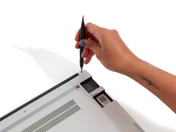
Using the T5 bit in the Framework Screwdriver, unscrew the fastener that is used to secure the Storage module.
-
Align the notch on the Storage module with the notch on the socket and slide the module into the Mainboard.
-
Once properly inserted the module will rise up at a 20-degree angle.
-
Using one finger gently hold the Storage module down to the Mainboard and use your other hand to screw in the fastener using the T5 bit in the Framework Screwdriver.
-
Be sure to not over-tighten the fastener.
-
-
-
Gently place the Input Cover keyboard side down on the Bottom Cover as indicated on the image. The cover should be about an inch and a half away from the bottom of the Mainboard so that you can comfortably install the Touchpad Cable.
-
Note: The orientation of the Input Cover matters. Study the first image in this step to ensure you are properly attaching the cover.
-
Locate the loop on the end of the Touchpad Cable and insert your finger into it.
"While flipped over, the top edge of the cover should overlap the bottom edge of the Mainboard by about an inch and a half so..." I think this would be a better way to phrase it.
Patrick Nolen - Open Reply
-
-
-
Using slight force, connect the Touchpad Cable by aligning it to the socket on Mainboard. You should hear it click into place once properly connected.
-
-
-
Before closing up the laptop, make sure that the Touchpad end of the Touchpad Cable is fully seated in the receptacle.
-
The cable should be inserted far enough that the white line almost touches the receptacle.
-
If it is not inserted far enough, you'll need to flip up the black latch on the other side of the connector, slide the cable in further, and then close the black latch again.
Can we please, please, please get a video for this step? The video should show: 1) what correct positioning looks like, 2) what incorrect positioning looks like, 3) what it looks like to go from incorrect to correct positioning. Clearly, there's a lot of confusion around this and this is a very fragile piece of the hardware.
Salman Shah - Open Reply
It would be helpful at this step, for Framework to include a photo of what a badly connected cable looks like, so that people can more easily see that white line on the border of the connector.
Eric the Cerise - Open Reply
Just wanted to +1 the idea of needing a bad example photo.
My cable seems to be glued down so I don't think I should have even been touching it.
Cody M -
@abc the green arrow indicates the direction (misleadingly) to open the black latch towards left. I think framework meant to show the "force" from right to left but from underneath the latch. The arrow should rather point upwards imho.
@pyoorkate the dsign hasn´t changed. You`re confusing the touch pad SIDE with the touchpad CABLE ends.
The touchpad side (end) came already assembled so no need to do anything. The white line is there just hard to spot when the side is already properly fitted :)
Confusing images as of this writing. What does the green arrow stand for and point to?
Provide images /photos with one image showing the cable not far enough in, and one image showing the cable properly fitting. And indicate with symbols inside the images which state is which
It appears the design of this component has changed, there's now a mylar sheet over the top, and no white line to check.
Your photo is showing the wrong end of the cable. You photographed the end of the cable that you just attached to the computer. This step is referring to the other side. Follow the 6 inch cable with your finger and you'll be at the side of the cable which connects to the underside of the keyboard.
Keith -
-
-
-
Once the Touchpad cable is secured to the Mainboard, flip the Input Cover over the Bottom Cover so that the keyboard is facing up and attach it to the Bottom Cover by aligning the top and bottom edges of both covers.
-
Tip: The covers are magnetic and should fit into one another easily. If you feel any resistance simply lift the Input Cover up and try again.
-
Note that the Input Cover will not sit entirely flat until the bottom fasteners are tightened. The bottom right corner is slightly lifted to make it easy to remove the Input Cover.
This was by far the hardest part in assembling my new Framework 13 with AMD AI 9 HX 370.
The top right corner (below the fingerprint reader) was impossible to sit completely flush, it's still not perfect even after screwing everything together, despite dedicating time to pull the WiFi cables and trying to route them better and refitting multiple times. A human hair can pass through the frame gap even after screwing everything together.
Had the same issue with the top right corner right below the fingerprint reader, spent an ungodly amount of time trying to fix it. Tried following Gelert, Dalton, and Emir's instruction but nothing really seemed to work. After a while I got it to a point where it was kind of flush but the bottom right corner seemed higher than it should. Just ignored it and continued, and after tightening the screws it seems okay.
Babafunmise - Open Reply
For people like me that need further explanation about the cable thing, your problem is that the two thin cables (antenna cables) are over the thick black wire and not under it in the topright corner, causing the input cover to bounce back on them and not snap in place perfectly. The picture Dalton provides shows how the cables should be arranged. I was hesitant to lift the adhesive of the black wire, so a workaround I did is to unscrew the network card off its place (found on the other end of the antenna cables, the first being the display), then threading the cable-card structure under the black wire so as to untangle any loops they form. This gives some freedom to rearrange them without ungluing anything. Just be careful not to damage the wires and to fit them back in place as you found them at the end. It might help checking out the tutorial about swapping the network card. Finally, after I did all that, the corner of the cover still was a teensy tiny bit lifted, on the same caliber as the other corners.
Going off Emir's comment: Ensure the antenna are running beside each other, parallel, and laying as flat as possible against the bottom case.
If the top right corner still isn't sitting flush, try lifting your webcam cable connector up and over the righthand hinge, like this.
I spent more time I'd like to admit battling the bezel and input cover, making sure they sit flush. Once I lifted the webcam cable over the hinge, everything sit flush on the first try.
Dalton Wood - Resolved on Release Reply
The top left corner of my cover plate annoys me a bit, since it is still slightly lifted even after tightening the festeners (only the part close to the hinge, where a cable goes to the monitor). I double checked that the cable was not in the way, but it is thick and has to go on to of the hinge. The other side is perfectly fit.
Pascal Belin - Resolved on Release Reply
If the keyboard seems a bit loose, don't worry; it will be tightened to the laptop in the next step.
Brett Cannon - Resolved on Release Reply
-
-
-
If installing a new Bezel, remove the liner pieces on the bottom of the Bezel to expose the adhesive (if present).
Applying the bezel on the display can take multiple tries, especially if you encounter the problem(s) mentioned in the previous and the next section. Just in case you get worried about the glue drying or whatever, I placed and removed the bezel multiple times, as well as letting it sit for a good while with the adhesive covers removed, and nothing bad happened.
It seems almost all of the comments here belong in the next section about actually installing the bezel - only a few of them (if any?) are pertinent to removing the liner pieces to expose the adhesive on the bezel, which is the only action taken here. It's a bit bonkers there's 17 comments before mine in this section about removing liner pieces and only 4 comments at the time of writing in the next section about bezel installation, the latter of which is clearly an order of magnitude more difficult it seems.
Richard Lloyd - Resolved on Release Reply
My bezel seemed to install well but the lower left hand corner ended up becoming quite stuck and warped for some reason (perhaps how a particular cable was positioned near the microphone).
It jammed and was almost impossible to open. I have had to detach the lower hinge of the bezel for now and will need a replacement.
Not the best experience.
Also had issues with the left corner of the bezel. What happened was I was trying to route the left corner cable below the hinge! That was stupid of me, but it seemed like the appropriate place for the cable to go without much knowledge of laptop bezels. I did fully read and follow the guide, and had the right cable properly fitted; but for some reason it seemed the left cable was supposed to fit under the hinge.
For anyone who might run into the same problem like I did, here is a picture of how the left cable is supposed to be properly seated:
Also, to be fair, the cable was already a bit seated under the hinge when I first opened the laptop, which led me to assume that was how it was supposed to be.
Ciaran Sanders - Resolved on Release Reply
the guide says "the ezel" instead of "the bezel" at the end of the 4th bullet point.
Chickenman - Resolved on Release Reply
For me this was really simple and took about 30 seconds.
Richard Tango-Lowy - Resolved on Release Reply
installed the bezel carefully, or so i thought, when i was finished closed the lid (top cover still off) and the captive screws levered the screen which caused the hinge cover at the bottom of the bezel to just shear off - awesome...i had to re-separate the bezel completely and install from the hinge cover first and then tip the laptop so the captive screws didn't catch in order to check the function again, working now but i've also got half a hinge cover separated from the bezel. Kind of took the shine off my laptop i've been waiting 4 months for
Surprisingly, the bezel was by far the hardest item to install for me. I found that it's easier if done without the top cover, however, be very careful to keep the screws fully seated in when moving the hinge - they can lodge themselves in the wrong spot and cause damage otherwise. This was also pointed out in a comment below, but it should really be a warning at the top of each guide.
As many have noted, the difficult part is getting the lower corners to sit flush. After a lot of tries the best technique I found is:
- release tension from the cables by taking them out from some of their holding brackets
- route them so that, with the laptop sitting flat and horizontal, their highest point is no higher than the hinge's. The picture in the guide shows how to do that - the hinge edges are skinnier than the rest, and you're trying to wrap around that tiny bit of space that they leave.
Even then it's not perfect and my bottom right corner wants to sit a hair higher than the others.
Demetrio Girardi - Resolved on Release Reply
I also had an issue when placing the bottom left of the bezel onto the screen. A cable connecting to the display was causing the the bezel to just not sit flush once it was closed. If you opened it with the cable misaligned it would cause the bottom left side of the bezel to jut out and really look like it would snap. If this guide could provide a picture on how the wiring of the bottom left should look it would be super helpful.
I managed to figure out how to position it after some troubleshooting, I just removed the bezel and kept closing the lid with the cable in a new spot. When the cable didn't pop out the back I tried it with the bezel installed, then closed the lid, then checked the back of the casing. I still noticed the bezel wasn't flush but after just pushing it up against the case it managed to snap into position and now seems to work fine after opening/closing the lid.
Vincent Becerra - Resolved on Release Reply
If the new bezel being aligned was not black it would more clearly demonstrate how to attach the new bezel.
I incurred two problems.
When installing my new purple bezel, I removed the left adhesive completely from the bottom of the Bezel when removing the liner piece. I was able to REapply it as it was sticky both sides.
I had more issues with the left hinge, in fact it snapped when I initially closed it. I was terrified but was thankfully able to dislodge it. I bloody well hope this will not effect the performance.
Very poor quality indeed, cheap flimsy plastic.
I did not trust myself to continue setting up my Framework Laptop 13 (13th Gen Intel Core) and put it away until I had more confidence.
Loretta Bozelle - Resolved on Release Reply
The bezel is cheap plastic and will break easy… if it happens to break it will start to cause issues. Will update with a pic, bezel definitely needs to be redesigned or done already assembled.
Cameron W Downie - Resolved on Release Reply
Two captive screws on the bottom of the laptop, near hinges, can mess with opening the screen fully if they are extended too far. Try to push them up (towards the motherboard) to avoid interference. In my case they even left a dent on the inner edge of the screen metal lid.
Andrew Bond - Resolved on Release Reply
On your picture, you already have installed the keyboard, which would be the next step in the process. Do the screws still stick out without the keyboard installed?
Same issue here, it somehow fixed itself after pressing the bezel a bit. It does click when I open the lid, though. I think the wire might need some tape?
Yochai Gal - Resolved on Release Reply
I was having issues as well. Check the wires that are tucked in on each side and make sure they are flush with the hinge. There was some tension with the wires and you can use the flat chisel side of the screwdriver tool to gently press the wires down into the chassis grooves.
The bottom right corner of my bezel is not fully pressed down along the display. It's only 1 or 2 mm raised, but it is noticeable when looking at the display from a side view.
Do not be alarmed if this happens to you as it seems others have experienced something similar based on posts in the community. I spent way too long repeatedly taking off and placing off the bezel to try and resolve it. All other edges of the bezel lay perfectly.
Sam Mikell - Resolved on Release Reply
-
-
-
Open the Framework Laptop 180 degrees to attach the Bezel.
-
Starting with the bottom of the Bezel which covers the hinges and cables, align the corners of the Bezel to the display and place it down. The Bezel is attached by magnets and should easily click into place.
-
We recommend feeling along each edge of the Bezel to make sure it is seated correctly before proceeding, if it doesn't seem to be sitting flush, lift it back up and try lowering it into place again.
-
Do not try to install the Bezel without first opening the Laptop fully, doing so could damage the Bezel and potentially the Display.
-
If the bottom of the Bezel doesn't seem to fit, lift it back off and check that the cables are seated correctly on both sides. If the Bezel doesn't seem to fit at all, please contact support and do not force it into place.
I also had some issues w/ the bottom left corner of the bezel catching on the display cable, that didn't present any issues until I tightened the screws on the baseplate, but since I opted for the transparent bezel, I could see where the problem was and resolve it. Just make sure the cable is not on top of and to the side of the hinge, like the other side, and that the adhesive on the cable isn't sticking it to the bezel, pulling it up.
Fair warning though, the transparent bezel is made of much more rigid and less flexible plastic than the normal one, and you will know when it's caught on something.
Jonathan Divall - Open Reply
We had four Laptop 13 Intel 13th Gen and now an AMD AI300 (Batch 4):
All of them had the glue cable patch on the left hinge not attached, so you really need to check this! Otherwise you will break the bezel (best case), the cable, or the hinge (worst case).
You have maximum force leverage at this point, so be really careful!
Yes I wrote this to frame.work, after I was lucky to only break the bezel on our first framework laptop :-S
Sad to see that this issue is still not fixed on their supply chain.
Torsten Dörschel - Open Reply
I join Lima Yankee on this unreported control, because of the cable, at the first opening, it unclipped me 1 good centimeter at the level of the Framework logo.
Bottom right corner is weird for me. At 180 its ever so slightly not flush, but outside that angle it seems okay. Decided I could live with that (might be related to the issues I had in the previous step). Also had the left bottom corner issue but like other comments said just tuck the cable in.
Babafunmise - Open Reply
The bottom-left of my bezel would not attach fully no matter what I did, and at one point it nearly snapped when trying to open the laptop and the lid would not open more than ~45-70 degrees. What I ended up doing is unfastening the bottom, gently removing the input cover, laying the laptop flat upside down for a while, and then re-opening it. I don't know why, but at this point I was able to remove the bezel (be gentle and do NOT try to force it as it's plastic). The reason my bezel would not sit flush is because the cable was routed incorrectly. It was underneath the hinge rather than above, and it also wasn't slotted into the red rectangle in this image. Make sure your cable is not sitting below or on top of the metal hinge and that it's correctly slotted here: https://imgur.com/a/TmDva6J
Aleksandr Hovhannisyan - Open Reply
Even after dealing with the cable thing, the bezel would give me problems. Very often it would bulge on the center or the right of the bottom side, especially when bringing the display to a 90degree angle. I found that it is kind of flexible, meaning that, with the other corners fit, i gently dragged it like a rubberband towards the last corner, forcing it to stay flat on its sides while snapping. It takes multiple tries and patience, just be very careful not to drag it too hard because I can tell from other people that it breaks fairly easily.
If the bottom right corner of the bezel won't click into place for you, or pops out of place when you open/close the lid, use the spudger end of your FW screwdriver to lift the webcam cable connecter over the righthand hinge, like this image. Don't worry about damaging the webcam cable, it's flexible, just be gentle.
Dalton Wood - Resolved on Release Reply
Just echoing the comments of David P and others below that a diagram and checkpoint on the display cable routing would be helpful here, as the cable routing arriving neat but passing the wrong side of the left hinge (ie on the input side of the hinge instead of the display side) ended up splitting the bezel on trying to close the laptop lid.
Second the cable routing check. Ours came with a bit of adhesive sticker on it, we removed and stuck it down behind the hinge.
Harry Hart - Resolved on Release Reply
If you have trouble getting the bezel to fit flush all the way around:
If there's a consistent place the bezel is usually unable to sit flush, try seating that point first and working your way around the rest of the bezel. Be gentle, but don't be afraid to take the bezel off and try again (it took a good number of attempts for mine to seat nicely). Gentle force is okay, but if it's not seating take it off and try again
NOTE regarding clicking while closing:
if the screws on the underside of the laptop, closest to the hinge, are held captive by the laptop body but dangling loose, when you try to close the laptop you may hear a crunchy click sort of sound as the bottom edge face of the bezel interferes with the screws. For me, picking up the laptop and orienting it so that the screws weren't dangling and sat more flush allowed me to close the laptop without issue, confirming this seemed to be my issue. You may also be able to screw in those screws ever so slightly so they're held more flush with the laptop body before putting the bezel on, but inspect the laptop and make sure you're not causing any problems before attempting, as this is not the recommend order of operations in the guide. You may not want to close the laptop all the way if you do this as the bezel may help to protect the screen
I think adding a clear picture of how the bottom cables should be dressed, or a diagram, would be helpful. With black cables on a black frame, it's hard to see what is supposed to happen and you can break your bezel easily.
Scott Thomphson - Resolved on Release Reply
Before installing the bezel, check the display cable is routed correctly as per this picture.
Lima Yankee - Resolved on Release Reply
At the left hinge, the cable seems to belong on the side closer to the display. Mine was on the opposite side, causing the bezel not to fit well, and after closing and reopening the lid, the bezel tore in this corner. It took a lot of wiggling and adjusting to free the bezel and move the cable to its correct position before the lid could be closed and opened easily.
"Starting with the bottom of the Bezel which covers the hinges and cables, align the corners of the Bezel to the display and place it down. The Bezel is attached by magnets and should easily click into place."
But the "bottom of the Bezel which covers the hinges and cables" is the bent/angled, part with the "framework" logo on it, no?
-
-
-
Close the Framework Laptop and turn it upside down to reveal the empty Expansion Card bays and fasteners on the Bottom Cover.
-
Using the T5 bit in the Framework Screwdriver, tighten all 5 fasteners.
-
Be sure to not over-tighten the fasteners.
-
-
-
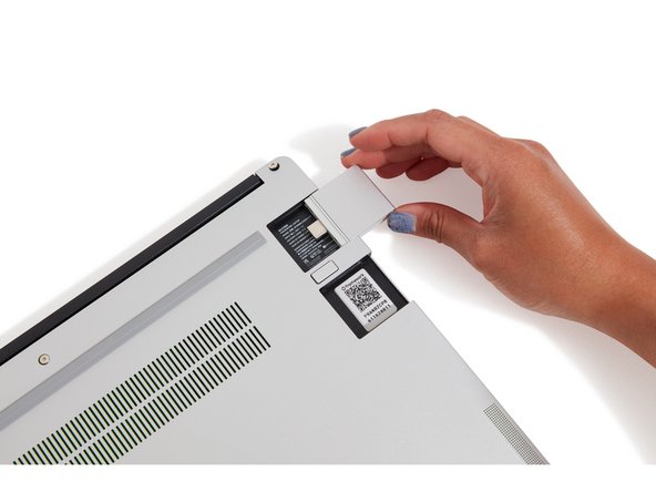
Insert the Expansion Cards of your choice into any of the empty bays.
-
The text, logo, and QR code on the Expansion Card must be facing down (facing the laptop). Slide the Expansion card into the bay. Using two or more fingers push the card until into the bay until it clicks.
-
You will have to use a slight amount of force to ensure proper installation of the Expansion Cards.
-
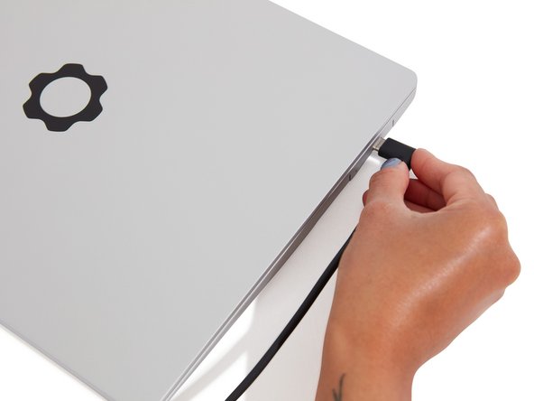
Plug your power cable into the USB-C Expansion Card.
-
Open the lid on your Framework Laptop and press the power button.
-
Note that your first boot will take a while before the logo comes up on screen as the system does memory training. The more memory you've installed, the longer this could take (on the order of a minute or two with 64GB!)
It took me 4 tries to get it to boot.
The first time, I tried without plugging in the power cord. I guess that is necessary, and you do say to do it, but a warning would help.
I saw a light between the expansion ports light up when I plugged in the power cord. The light on the other side of the laptop did not light up.
Even then, pressing the power button didn't do anything.
After waiting 2 minutes each time, I started paying closer attention to the light around the power button itself. At first I thought it would only momentarily flash when I turned it on. But now I'm guessing that by holding the button down for a slightly longer fraction of a second, I was actually turning it off or something.
Finally, after noticing that the little lights between the expansion ports were on on both sides of the laptop, I tried pressing again, this time for a shorter time, and the light around the power button stayed on this time. Yay!
I suggest being much more clear about the indications we should look for.
Neal McBurnett - Resolved on Release Reply
Thank you Neal McBurnett, I had the exact same issue you described. I completely reassembled the laptop and followed each step again and then I saw your post. You made my day. Thanks.
Dirc -
When I turned my new laptop on for the first time, I received an error message saying boot device not found and boot failed. Framework Support said this occurred because I hadn't yet created a bootable USB disk using the Windows Media Creation tool, which is covered in the next step. I think there is an issue with this guide in that step 12 incorrectly suggests you will be able to boot up before completing step 13.
My left-side expansion cards didn't work initially; I had to use the right side both for the initial charge (which enables the battery) and for the USB stick (to install Windows). Once I'd installed Windows and the Framework driver package, all my expansion cards were working. I suspect the right-side cards are native and the left side require drivers to work.
Tim Meneely - Resolved on Release Reply
I wasn't told that I needed a USB c expansion card.. I'm just going to have to unplug one of my expansion cards which is pretty much useless now
Kari VanPelt - Resolved on Release Reply
Mine turns on but the screen does not show anything, and it's been a couple hours.
Same. I had to wait for the battery to fully charge to be able to see the POST blink codes on the side LEDs. POST failed on DDR init.
My setup has a single 32GB SODIMM in the channel 0 (right) slot. Tried resetting the board and reseating the SODIMM after blowing out eh socket with no success.
What finally worked was moving the SODIMM to channel 1 (left slot), letting it boot, then back to channel 0 (right slot), after which the system has been fine. I suspect the memory training failed and switching slots around forced a reset of that. Dunno.
David -
Same here. It hasn't been hours but at least 15 minutes. The initial memory check mentions one or two minutes so this does not feel right. It is on and blowing a lot of hot air but nothing on the screen yet...
-
-
-
Find the instructions for installing Windows 11 here.
-
If you use Rufus, Ventoy, or other tools instead to create the installer, you'll need to follow the steps in this article, otherwise you will run into an error during installation around netwtw10.sys.
-
The Framework Laptop is designed to work great with Linux too. Check out our Linux compatibility page for distros we recommend, like:
-
Fedora 38- Essentially fully functional out of the box.
-
Ubuntu 22.04 LTS - Essentially fully functional out of the box.
-
-
-
If you're using Windows, you'll also need to install the latest Framework Laptop Driver Bundle.
-


- To purchase a Framework Laptop visit the Framework website
- Want to learn more about the Framework Laptop? Take a look at our blog
- If you have any questions or concerns, feel free to reach out to Framework Support
- To purchase a Framework Laptop visit the Framework website
- Want to learn more about the Framework Laptop? Take a look at our blog
- If you have any questions or concerns, feel free to reach out to Framework Support
Cancel: I did not complete this guide.
17 other people completed this guide.
One Comment
If you really want more people to do this, please add a link to the article about electrostatic discharge (https://knowledgebase.frame.work/all-abo...) to the beginning of this article!
Double check that note about the RAM being under the power supply. Wish they would put a note in the box about it...
Tanner Davis - Resolved on Release Reply
Note to Framework & users just beginning this set-up adventure:
If you’re like me, and you don’t do this sort of thing frequently, then you don’t have USB drives laying around just waiting to be used. Before you get started, make sure you purchase a USB drive that has at least 8 GB of free space. It will be important to have one the laptop is assembled and you get to the part of installing your OS.
Eclectic - Resolved on Release Reply