
Introduction
After over a year of prototyping and experiments, we've been able to come up with a way to reduce system power consumption when an HDMI Expansion Card is present, by making the card pretend that it is not a display output when there is no monitor connected.
You can rework an existing HDMI Expansion Card to have this behavior by following this guide to solder a jumper wire internally and flash new firmware to it. Note that this requires advanced soldering skills, so we recommend that you only try it if you're familiar with extremely fine-pitch SMT rework and have the necessary tools for it. Damage caused by failed reworks is not covered under warranty.
Beta release: Note that the firmware and instructions are still in beta, so there may be further revisions. The firmware update tool from our supplier currently is only available for Windows. We're also running a beta test with 2nd Gen HDMI Expansion Cards with Batch 1 of 13th Gen that has a slightly different modification.
Parts
No parts specified.
-
-
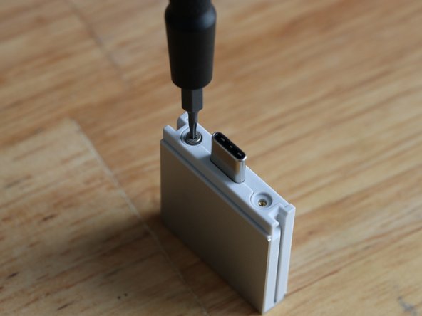
With the T5 bit in your Framework Screwdriver, remove the two fasteners holding the lid onto the Expansion Card.
-
Hold the Expansion Card with both of your thumbs on the lid and slide the lid towards the USB-C plug. It will take a little force to get the lid to unlatch.
-
-
-
Using the T5 bit in your Framework Screwdriver, remove the two fasteners that hold the PCB in. This will let you get to the underside of the PCB, where you'll solder the jumper wire.
-
-
-
This is the hard part! We recommend using a 28 AWG solid wire about 7mm long, along with a microscope, tweezers, a fine tip soldering iron, a tiny amount of solder, and some soldering flux. It takes very little solder to make the connection.
-
If you're at this point looking at the tiny pads and wondering about the steadiness of your hands, it is totally ok to turn back now rather than risking damaging the card. This is definitely a non-trivial soldering exercise.
-
In the first image, you can see the two points that need to be connected. The right pad on the unpopulated resistor footprint, to the third pad on the IC.
-
If your HDMI Expansion Card has a resistor on the footprint that the left orange arrow is pointing to, remove the resistor first.
-
In the second image, you can see an example of a wire soldered into place. Note how little solder is used for the connection. Be extra cautious to not use too much solder, bridging to other contacts, but enough solder that the circuit is solid. Take a close look with a microscope to ensure the solder joint is good.
Can you get more specific with the wire recommended? It appears to be either bare tinned copper wire or bare stainless steel wire in the pictures. I would think tinned copper would be easier to solder than steel, but I don't have real world experience with either. Could you use insulated hookup wire to make sure you are not accidentally connecting to any of the other components with the bare wire?
-
-
-
Screw the PCB back into place using the two black T5 fasteners.
-
Slide the lid back on, and screw it on using the two silver T5 fasteners.
-
-
-
Now that you've completed the hardware part of the rework, you can reflash the HDMI Expansion Card with the new firmware. Note that we currently only have a Windows-based updater available from our supplier.
-
Download the HDMI Expansion Card version 105 firmware here. Unzip it. With the HDMI Expansion Card plugged in, run Framework_HDMI_Card_3.0.16.105.exe. After the update completes, you can run Framework_ReadVersion.exe to confirm that both "Image 1 version" and "Image 2 version" state 3.0.16 build 105.
-
We also recommend marking the card in some way to indicate that you've modified it, in case you have multiple cards in the future.
Does this still affect HDMI Expansion Cards or are later ones patched and already have the trace?
-


With the rework completed and the firmware flashed, you can expect to see improvements in power consumption in different scenarios. Make sure you're also running the latest firmware on your laptop to see the full results.
With the rework completed and the firmware flashed, you can expect to see improvements in power consumption in different scenarios. Make sure you're also running the latest firmware on your laptop to see the full results.
Cancel: I did not complete this guide.
7 other people completed this guide.
23 Comments
For anyone suffering like @amoonrabbit did, the trick is to have something to soak up the heat in the middle of the wire, so holding the wire in place with helping hands jaws or similar will usually help stop the heat from flowing through the fine wire to the other pad and causing it to desolder itself.
Can we install the updated firmware without doing the soldering? Obviously we woudn't get the full benefit, but would it give any benefits, such as slightly better power efficiency, or better compatibility with external monitors like the 3rd gen HDMI cards? Or would it not work at all?
The flashing tool only works in a framework laptop? I mean, could I connect the expansion card to another laptop and flash the firmware there?
Manuel Carvajal - Resolved on Release Reply
Yes, you can. I even flashed it successfully in another Windows-PC – that had no USB-C interface – by using an USB-C to USB-A adapter. Though, it was USB-A 3.0, of course.
After the mod in windows 11 I get a warning that the USB device is not recognized if no HDMI cable is plugged in and if I plug in a device via HDMI, everything works fine. Under Linux MINT 22, I get not warning. I hope this is normal... Nevertheless, everything seems to work fine :)
BTW: This mod is really really difficult, I almost gave up after 2h of work (However, I had no SMD experience nor a microscope) and I think I only did it by chance.
Very fiddly. Working with a magnifier on a helping hand, a strand of wire from a mm thing wire, and not the finest soldering tip on my TS100. Everytime I went to solder the pad end, the chip end would come free. A lot of patience required, but I eventually got a connection on both ends.
Needed to do this as my Samsung monitor pre-mod was limiting display refresh rate to just 30Hz at 4k, having done this mod, and flashed the new firmware I now have 4k@60Hz. No need to buy a new module.
AMoonRabbit - Resolved on Release Reply
I'm following up on this and hoping you can share the 3.0.16 build 980 firmware update for the HDMI v2 modules so I can fix mine? Or should I contact support?
I realized my past post had an error, however the short of it is that after running the v3 update file on my v2 module, the firmware reports as being downgraded to 3.0.16 build 105. Originally it was 3.0.16 build 980, so you can see the issue here?
Thank you in advance! Sorry I don't check this page often, but I would like to run the proper firmware if this older build will cause other issues.
Caleb Morche - Resolved on Release Reply
Hello! I'm making a duplicate of my comment as a new post as I'm not sure if it will be noticed within the others.
I own both the 1st and 2nd gen editions of this card, but I mistakenly ran the firmware update for the 3rd gen and it changed my 2nd gen card to now report the firmware as "3.0.16 build 105", which is older/different from the firmware that coriginally ame with the card, "3.0.16 build 980".
How can I revert my 2nd gen card back to "3.0.16 build 105"? Or am I now stuck with "3.0.16 build 980"? What issues might this cause, if there are indeed hardware differences between the 2nd and 3rd?
Thank you!
Caleb Morche - Resolved on Release Reply
3.0.16 build 105 is actually a newer firmware than 980, but was designed for 3rd Gen. We haven't tested it on 2nd Gen, but if it seems to be working, there probably isn't a strong reason to change it.
Hello,
I'm following up on this and hoping you can share the 3.0.16 build 980 firmware update for the HDMI v2 modules so I can fix mine? Or should I contact support?
I realized my past post had an error, however the short of it is that after running the v3 update file on my v2 module, the firmware reports as being downgraded to 3.0.16 build 105. Originally it was 3.0.16 build 980, so you can see the issue here?
Thank you in advance! Sorry I don't check this page often, but I would like to run the proper firmware if this older build will cause other issues.
Both the updater and the checker throw DLL errors when trying to open them, including when running as administrator. Using Windows 11.
Christopher B Burtraw - Resolved on Release Reply
Figured it out. I had installed Visual C for x64 after googling the DLL issues, but you need the x86 (32 bit) version to get the DLLs needed to run these programs. FYI it seems you can have them both installed at the same time no problem. I recommend adding this to the guide that specifically 32 bit / x86 Visual C is needed, it does not come with Windows by default.
Can you please share the firmware for the v3 HDMI adapters? I have a v2 and stupidly thought that this firmware update was the latest (since my native v2 card already has the hardware mod), and I ran it only to realize that now I am running an older release of "3.0.16 build 105" which is older than the firmware that came with the card originally "3.0.16 build 980".
If you cannot release the v3 update, could you please post the 3.0.16 build 980 update please, so that I can restore my card?
Thank you! - Caleb
Caleb Morche - Resolved on Release Reply
Hello Nirav!
I own both the 1st and 2nd gen editions of this card, but I mistakenly ran the firmware update for the 3rd gen and it changed the 2nd gen card to now report the firmware as "3.0.16 build 105" which is older than the firmware that came with the card originally "3.0.16 build 980".
How can I revert my 2nd gen card back to "3.0.16 build 105"? Or am I now stuck with "3.0.16 build 980"?
Thank you!
Modifying a 2nd Gen into a 3rd Gen requires making both the hardware modifications noted in this guide and applying the firmware update. Build 105 is only compatible with 3rd Gen (or 1st Gen or 2nd Gen cards modified to become 3rd Gen).
I've been practicing my micro soldering skills and am getting close to being comfortable enough to give this a try. However, I have a couple of questions regarding this section of the guide:
Beta release: Note that the firmware and instructions are still in beta, so there may be further revisions. The firmware update tool from our supplier currently is only available for Windows. We're also running a beta test with 2nd Gen HDMI Expansion Cards with Batch 1 of 13th Gen that has a slightly different modification.
1. What are the chances that the hardware modification instructions are going to be revised? I'm ok with re-flashing the firmware at a later date, but having to undo and redo this soldering would be pretty lame.
2. What are the chances of being able to flash the firmware under Linux, as I'm not a Windows user?
1. Unlikely. This connects the MCU to the pin required for detecting whether there's a monitor connected. So there's no need to remove it in the future.
2. We'll release a Linux updater for it soon, and it'll be supported in FWUPD/LVFS a bit later.
Successfully implemented this on 2x HDMI expansion cards. Immediately improved battery runtime although I didn't attempt to make quantitative power draw before/after measurements.
The flashing tool seems to only operate on the first module identified. I had two modules installed and had to remove one of them to flash the other.
Ryan Crisp - Resolved on Release Reply
You could add a suggestion to the guide to ask a repair shop to do it, if one isn't familiar with the process.
That avoids eWaste and might also be a marketing avenue on top
Samuel Maier - Resolved on Release Reply
For those of us not electrical engineers, I wish framework would have a swap program setup.... I am not capable of soldering something so tiny!
Considering its a value add instead of a break/fix it's totally understandable that they do not have a swap program. If you don't want to risk breaking it you can always buy a v2 when it comes out. The fact that they post instructions for the dozens of us that will do this mod is incredible. I found it to be a fun little project.
Easiest way is to take the card and a link to this guide to your local repair shop. Soldering a jumper wire might be challenging for a beginner, but repair shops that do them do them often for different devices. The problem when they can't is usually a lack of schematics rather than them not having the tools and skill to do it.
Not all repair shops do component-level repair, but if they don't they will definitely know someone who does and it should be relatively cheap.
Alternatively, search for Louis Rossman's guides on YouTube. He has some content on how to repair Macbooks, and covers jumper wires in many of them.
I'd like to see better clarification of which revision(s) of HDMI expansion cards this modification is suitable for. Preferably with enough information to avoid mistakes, even if you're not sure which revision card you have. Perhaps either the "2021.03.25" or the "Cto HDMI_V3.0HF" on the PCB are enough to identify all the cards that this modification is suitable for? Also, it seemed slightly unclear to me what "beta test with 2nd Gen HDMI Expansion Cards" referred to, but I guess you mean they are/were being supplied with a modification already included?
Brian Gregory - Resolved on Release Reply
Sliding the lid off took quite a bit more force than I was expecting, but it did eventually break loose.
GJason - Resolved on Release Reply
If your thumbs slide on the cover, use a piece of a rubber balloon between thumbs and cover to improve traction.
Louis Puster - Resolved on Release Reply