
Tools
Parts
-
-
Power off the Framework Laptop by navigating to the Windows icon on the bottom left and clicking on "Power" followed by "Shut down," or if on Linux, the equivalent action there.
-
-
-
Unplug your power cable from the USB-C Expansion Card in your Framework Laptop.
(I had formerly left a long comment here about how you guys 'forgot' to have a bit about removing the expansion cards...and while some official guide on this is probably a good idea to have, it's...not actually necessary to remove them! Even though in the build guide, they go in last, they don't actually need to come out in order to replace the screen! Heh.)
-
-
-
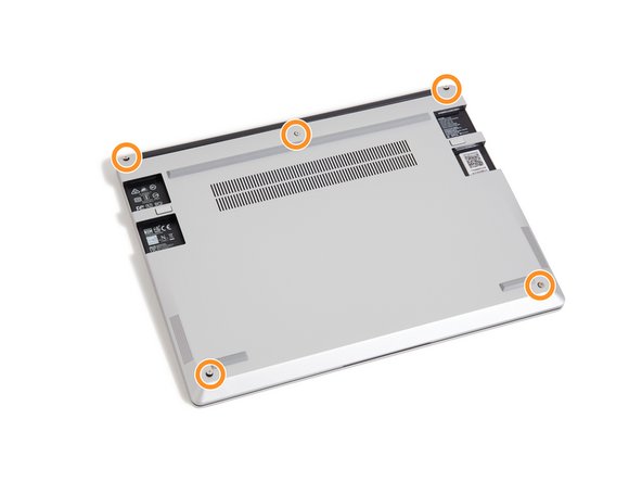
Close the lid on your Framework Laptop and place it upside down on a soft, non-marring surface, such as the bag that it shipped in.
-
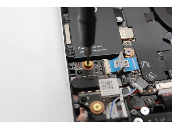
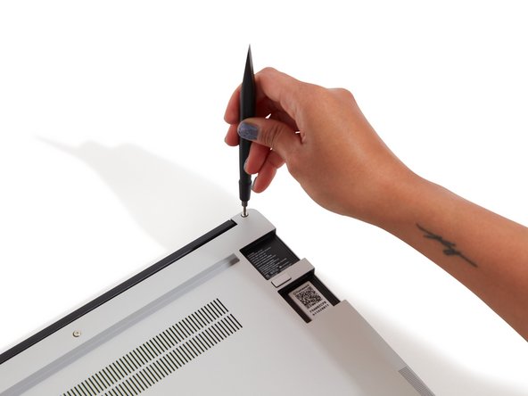
Using the T5 bit in the Framework Screwdriver, unscrew the 5 fasteners on the Bottom Cover. These fasteners will remain attached in the Bottom Cover so that you do not lose them.
-
The fastener on the bottom left (circled in red) will not unscrew as far as the others, as it is acting as a lifter for the Input Cover.
-
You'll hear this fastener start clicking as you rotate when it is unscrewed far enough.
-
Do not use a powered tool for these steps, as this will likely result in damage to the fasteners.
It would be super nice if the lower-left screw were circled in red as the text indicates!
Mike Shaver - Resolved on Release Reply
Thank you for writing the specific detail on the lower left corner screw.
I thought something was not working correct until re-read this guide.
Patrick Corey - Resolved on Release Reply
-
-
-
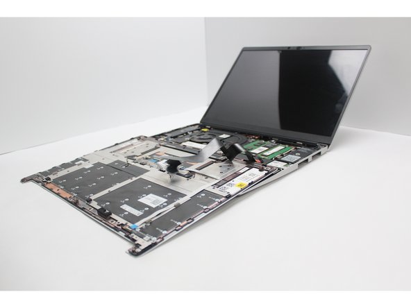
Flip the Framework Laptop back over and open the lid to around 120 degrees.
-
Important: Pull the Input Cover off carefully as it is still attached to the Mainboard via the Touchpad Cable. You don't need to disconnect this cable to do most repairs. You can just flip the Input Cover over. If you do want to disconnect it though, make sure to disconnect the Mainboard side using the finger loop over the orange label.
-
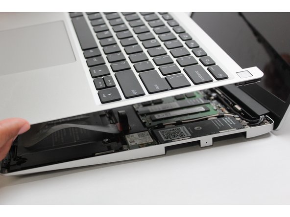
The bottom right corner of the Input Cover lifts up when the five fasteners are properly unscrewed from the previous step. You should not have to use any excessive force to remove the Input Cover.
-
Carefully lift the cover up from the bottom right corner. If you need to, you can use the spudger end of the Framework Screwdriver to lift it as well. Lift the Input Cover off the Mainboard, flip it over (keyboard side down), and place it about halfway on the Bottom Cover.
-
Be sure not to put too much force on the Touchpad Cable when doing this.
-
If the LEDs on the left and right sides of the system are flashing red when you lift off the cover, it means the system is still powered on. Make sure your power cable isn't plugged in and that you have shut down correctly.
-
Note that it may take up to 30 seconds after shutting down for the system to fully power off. Wait until the LEDs stop flashing before proceeding.
-
You should keep the Battery connector plugged in unless you need to replace the Battery, Mainboard, or Speakers. This connector is easy to accidentally damage, so it's better to not handle it.
Important: Pull the Input Cover off carefully as it is still attached to the Mainboard via the Touchpad Cable. You don't need to disconnect this cable to do most repairs. You can just flip the Input Cover over. If you do want to disconnect it though, make sure to disconnect the Mainboard side using the finger loop over the orange label.
While that’s true for most repairs, it’s pretty much essential to disconnect that cable for this repair, so I think the guide should probably amend this boilerplate!
Mike Shaver - Resolved on Release Reply
You should flip the keyboard around the x-axis (so that the back edge comes towards you as you flip) and not the z-axis (resulting in the left edge rotating to the right). I started to do the z-axis and the touchpad cable was getting twisted. I am capable of messing up all instructions. This is my anti-super-power... or joker power in the Wild Cards universe.
-
-
-
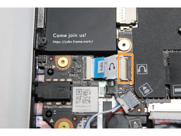
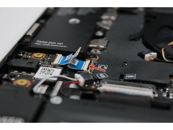
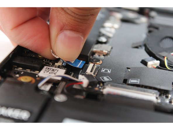
Using your fingernail or the spudger end of the Framework Screwdriver, flip up the black latch on the connector.
-
Slide the cable straight out of the connector.
-
-
-
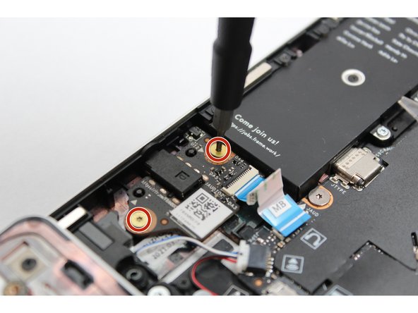
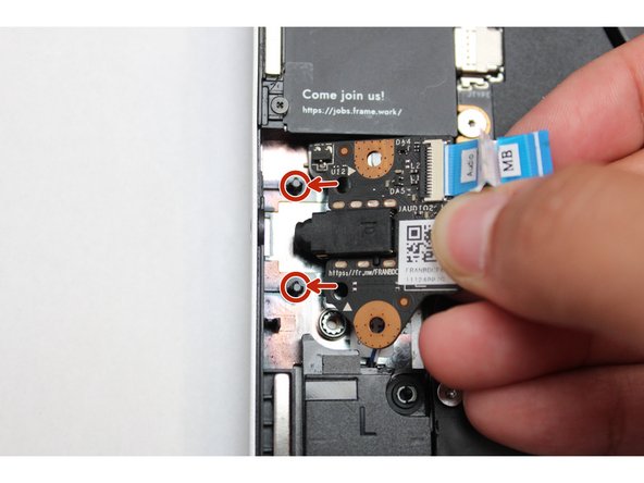
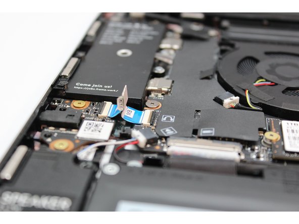
Using the T5 bit in the Framework Screwdriver, unscrew the two fasteners on the Audio Board.
-
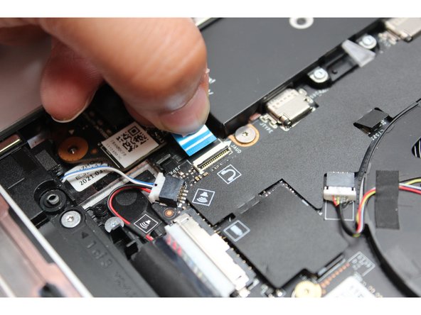
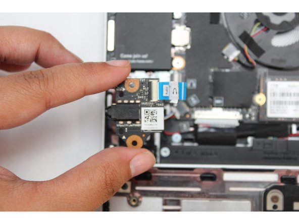
Using your finger or the spudger end of the Framework Screwdriver gently lift up the Audio Module from the right-hand side and pull it away from the headphone jack.
-
-
-
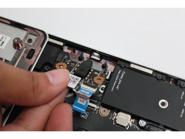
Place the Audio Board down by aligning the holes on the Audio Board with the alignment pins on the Bottom Cover and insert the headphone connector through the hole on the left hand side of the Bottom Cover.
I found it much easier to FIRST do step 9 (connect the audio cable) THEN do step 7 (install the audio board) then 8 (fasten the screws). The cable on the sound board (80 decibels) I got had a shorter cable with the tab at a right angle to it and it was very awkward trying to get the cable into the socket on the mainboard with the sound card in place. But it was very easy with the sound board not attached. It was still very easy to insert the sound board even with the cable attached at both ends.
I would suggest changing the order of the steps to
insert cable into socket on the mainboard (lifting lock tab, etc.),
insert sound card,
fasten sound card tools.
That order makes it vastly easier to insert the cable into the socket on the mainboard, at least with the 80 DB sound card.
i
Jim Barron - Open Reply
-
-
-
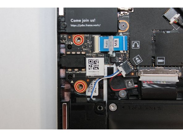
Using the T5 bit in the Framework Screwdriver screw in the two fasteners.
-
-
-
Insert the Audio Cable back into the Mainboard. Make sure the black latch is flipped up so that you can slide the cable into the connector.
-
Slide the cable in until the white line is almost at the edge of the connector.
-
Flip the black latch down to secure the cable in place.
-
The Audio Board is now installed.
-
-
-
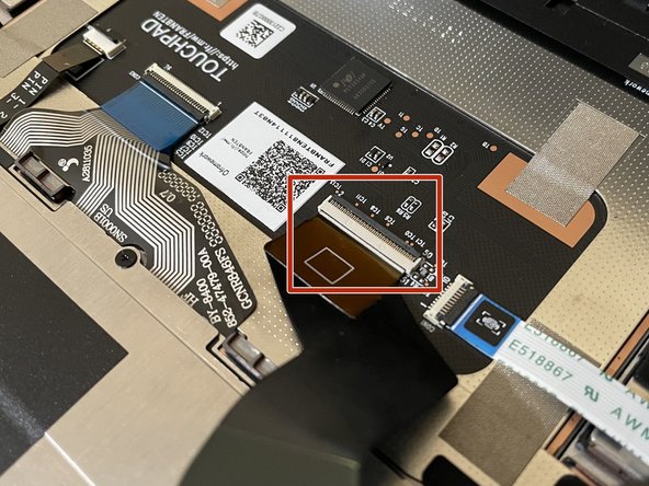
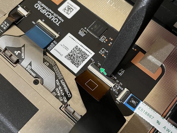
Before closing up the laptop, make sure that the Touchpad end of the Touchpad Cable is fully seated in the receptacle.
-
The cable should be inserted far enough that the white line almost touches the receptacle.
-
If it is not inserted far enough, you'll need to flip up the black latch on the other side of the connector, slide the cable in further, and then close the black latch again.
-
-
-
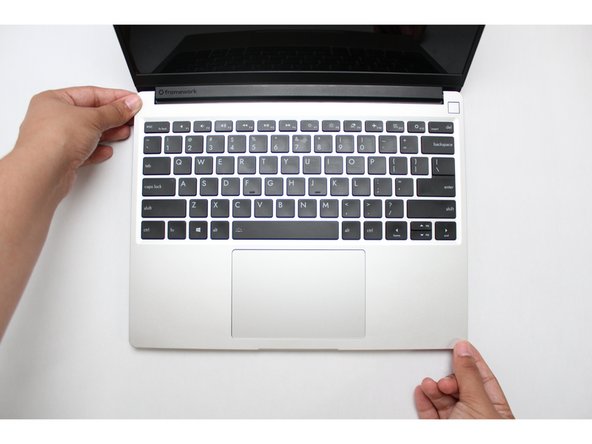
Flip the Input Cover over the Bottom Cover so that the keyboard is facing up and attach it to the Bottom Cover by aligning the top and bottom edges of both covers.
-
Tip: The covers are magnetic and should fit into one another easily. If you feel any resistance simply lift the Input Cover up and try again.
-
-
-
Close the Framework Laptop and turn it upside down to reveal the five fasteners on the Bottom Cover.
-
Using the T5 bit in the Framework Screwdriver, screw all 5 fasteners back into the Bottom Cover.
-
Be sure to not over-tighten the fasteners.
-


- To purchase a Framework Laptop visit the Framework website
- Want to learn more about the Framework Laptop? Take a look at our blog
- If you have any questions or concerns, feel free to reach out to Framework Support
- To purchase a Framework Laptop visit the Framework website
- Want to learn more about the Framework Laptop? Take a look at our blog
- If you have any questions or concerns, feel free to reach out to Framework Support
Cancel: I did not complete this guide.
7 other people completed this guide.
Before even starting, inspect the new board to be sure all the connectors are ok. Mine had the speaker connector broken off.
Gary Aitken - Resolved on Release Reply
@ahappykittycat I wish that I had read your comment before I undertook this…
Mike Shaver - Resolved on Release Reply
IMPORTANT: If you plan to install your existing mainboard in a CoolerMaster case, make sure to boot into the BIOS and enable standalone mode before continuing.
Richard Tango-Lowy - Resolved on Release Reply
Pretty sure you might want to include a reminder to backup the bitlocker recovery key if it is enabled. The system will definitely boot to the bitlocker recovery screen since it will be a different TPM.
James Wu - Resolved on Release Reply
It could be helpful to give the bash terminal command to shutdown such as
Patrick Corey - Resolved on Release Reply
Bottom left*
Vijfhoek - Resolved on Release Reply