
Introduction
Before you get started, if you are running Windows, there are a few steps you'll need to take:
- If you're using Windows 10, we recommend upgrading to Windows 11 before swapping the Mainboard.
- Make sure you back up your data.
- If you’re running a Pro version of Windows, suspend BitLocker by following our directions here.
- If you're running a Home version of Windows and have enabled Windows Device Encryption, you will want to disable it. To disable it, press Win + I to open Settings and select Privacy & Security. Then, click on Device Encryption on the right panel and toggle the setting to Off.
- Find your product key or link your Windows license to a Microsoft account to make sure you can re-activate Windows after the change.
If you have any questions or run into issues, check out our Support pages.
Tools
Parts
-
-
Power off the Framework Laptop by navigating to the Windows icon on the bottom left and clicking on "Power" followed by "Shut down," or if on Linux, the equivalent action there.
-
-
-
Unplug your power cable from the USB-C Expansion Card in your Framework Laptop.
(I had formerly left a long comment here about how you guys 'forgot' to have a bit about removing the expansion cards...and while some official guide on this is probably a good idea to have, it's...not actually necessary to remove them! Even though in the build guide, they go in last, they don't actually need to come out in order to replace the screen! Heh.)
-
-
-
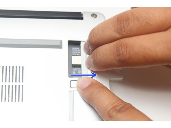
Close your laptop completely and turn it over so you can access the Expansion Cards.
-
While keeping the release button pressed, use your other fingers to slide the Expansion Card away from the laptop.
-
Important: You may have to use a little bit of force to fully disconnect the Expansion Card.
-
Make sure each Expansion Card is fully removed before proceeding to the next step.
-
-
-
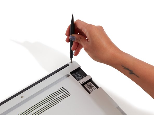
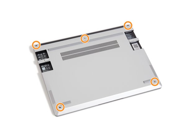
Using the T5 bit in the Framework Screwdriver, unscrew the 5 fasteners on the Bottom Cover. These fasteners will remain attached in the Bottom Cover so that you don't lose them.
-
The fastener on the bottom left (circled in orange) won't unscrew as far as the others, as it is acting as a lifter for the Input Cover. You'll hear it start clicking as you rotate when it is unscrewed far enough.
-
-
-
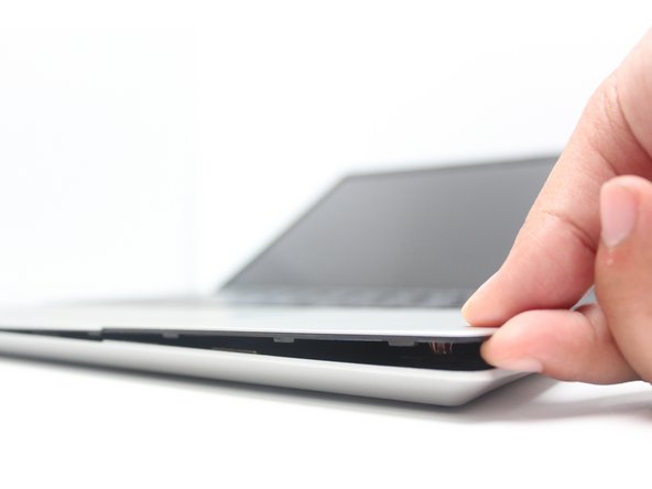
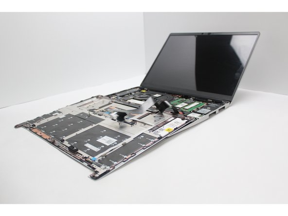
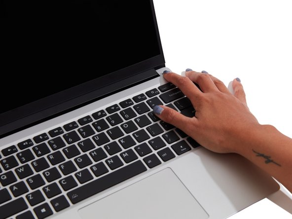
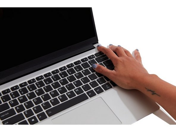
Turn the Framework Laptop over and open it to 120 degrees.
-
The bottom right corner of the Input Cover lifts up when the five fasteners are properly unscrewed from the previous step. You should not have to use any excessive force to remove the Input Cover.
-
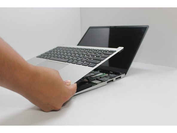
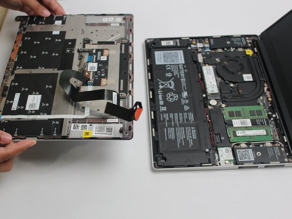
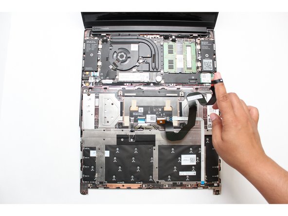
Carefully lift the cover up from the bottom right corner. If you need to, you can use the spudger end of the Framework Screwdriver to lift it as well. Lift the Input Cover off the Mainboard and flip it over (keyboard side down) and place it about halfway on the Bottom Cover.
-
Important: Do not pull the Input Cover fast or with too much force as it is still attached to the Mainboard via the Touchpad Cable.
-
-
-
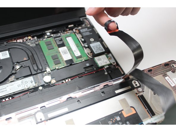
Disconnect the Touchpad Cable from the Mainboard by inserting your finger into the loop and pull directly upward using a slight amount of force.
-
Once the Touchpad Cable is disconnected, remove the Input Cover away from the Mainboard.
-
-
-
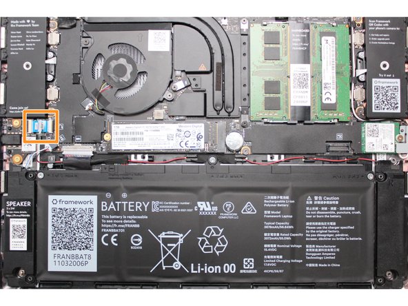
Be extremely careful when sliding the Battery connector out, as it is very easy to accidently bend the pins. Make sure to slide straight down, and avoid letting the connector twist or bend.
-
Gently disconnect the Battery by gripping the connector edges with both fingers and slide the connector straight down from the socket.
-
-
-
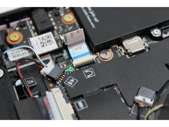
Using both fingers and a slight amount of force, disconnect the Speaker cable from the Mainboard by pulling it straight out.
The cute, helpful icons for each connector aren't on the Framework 13 AMD 7040 series, but everything is in the same place as shown. But dang, I wish I had those icons. #BringThemBack
Brody Brooks - Resolved on Release Reply
-
-
-
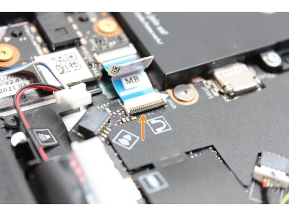
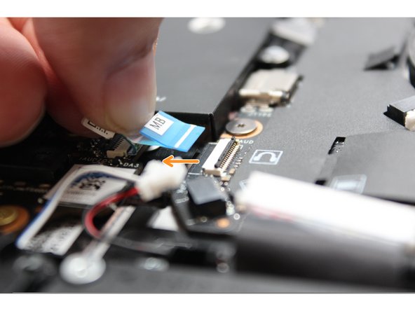
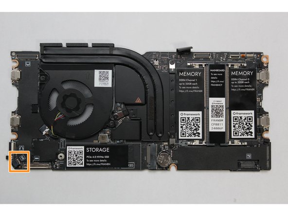
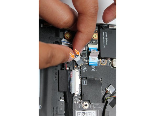
Disconnect the Audio Flex Cable from the Mainboard. Using your fingernail or the spudger end of the Framework Screwdriver flip up the black latch on the connector and then gently slide the cable out of the connector.
-
There should be no resistance when disconnecting this cable.
Each of the photos magnifies when you hover the mouse over it. The latch is a tiny sliver of black plastic, maybe 9 mm x 1 mm, oriented with the y axis (from the perspective of the 1st and 3rd photos), to the right of the audio cable connector. It lifts up gently, rotating slightly to the left.
-
-
-
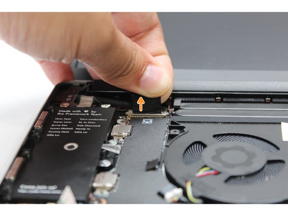
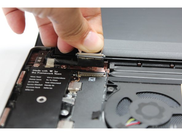
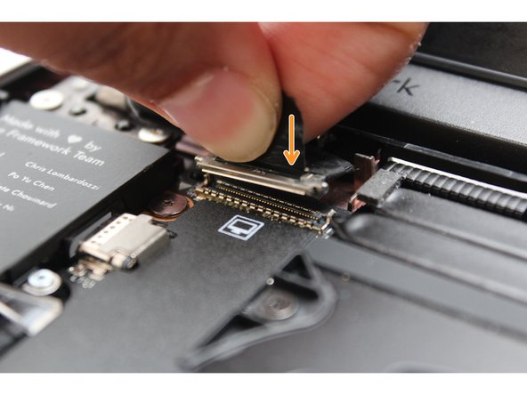
Using your fingers, carefully disconnect the Display cable on the top, left hand side by using the pull tab to pull it upward.
-
-
-
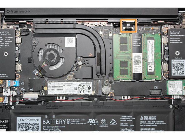
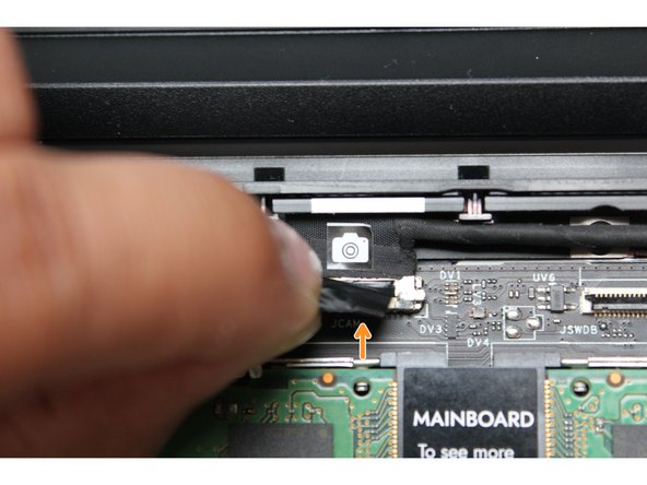
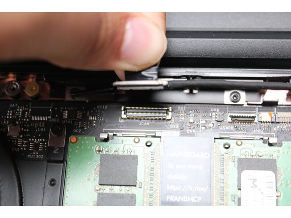
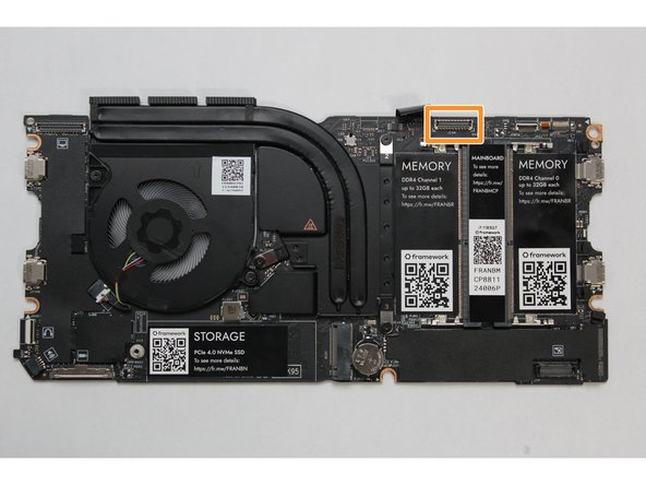
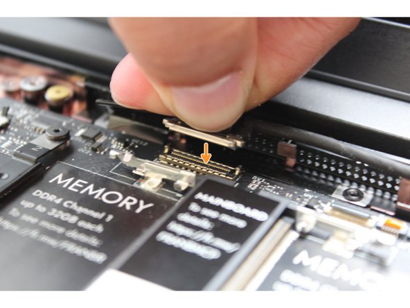
Using your fingers, carefully disconnect the Webcam cable on the top, right hand side by using the black pull tab to pull it directly upward.
-
-
-
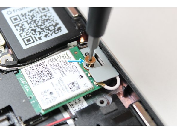
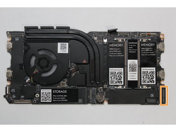
Using the spudger end of the Framework Screwdriver, release the black and white WiFi Antenna cables by gently lifting them out from the rubber holders.
-
Unscrew the fastener in the silver bracket holding down the WiFi module.
-
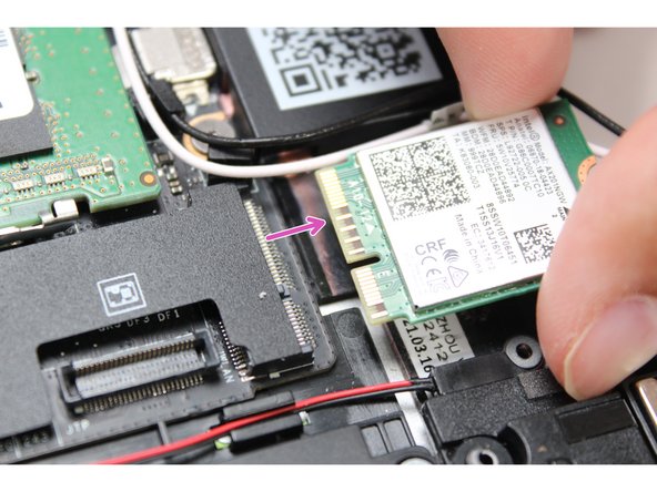
Remove the WiFi bracket and gently pull the WiFi module out of the socket as indicated in the image.
-
You do not need to disconnect the black and white WiFi Antenna cables from the WiFi module. Keeping them connected will make it easier to insert the card back into place.
The cable clips are very poorly adhered to the mainboard; one of mine was floating free, still attached to the wires; and a second one came loose when reinstalling.
Gary Aitken - Resolved on Release Reply
-
-
-
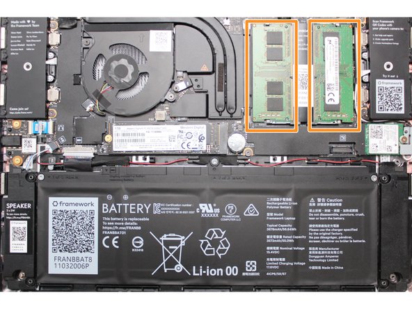
If there is black shielding over the RAM slots, do NOT remove it. These are necessary to reduce interference with Wi-Fi.
-
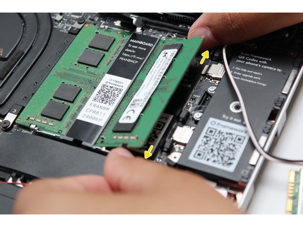
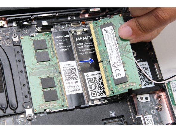
Using both fingers, gently pull the top and bottom metal release clips away from the Memory just enough for the module to pop up.
-
The top and bottom clips should be released simultaneously for a single Memory module.
-
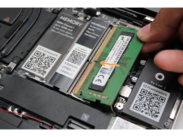
The Memory module will pop up at a 20 degree angle. Carefully slide it out of the socket and remove it from the Mainboard.
-
If you have more than one Memory module in place, repeat the steps for the other module.
-
-
-
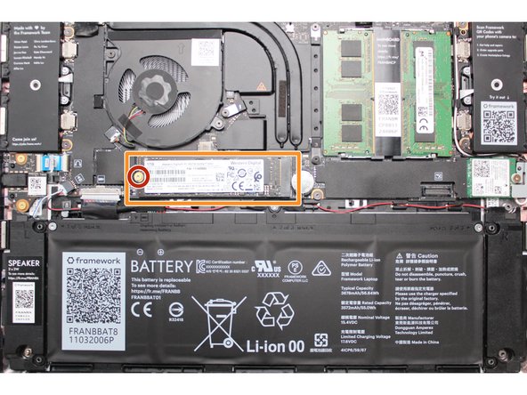
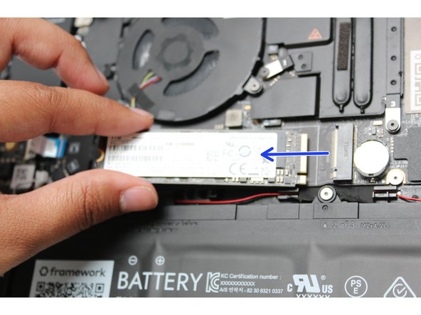
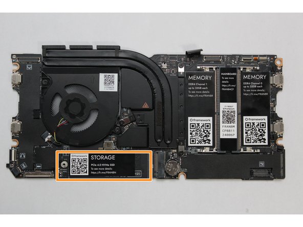
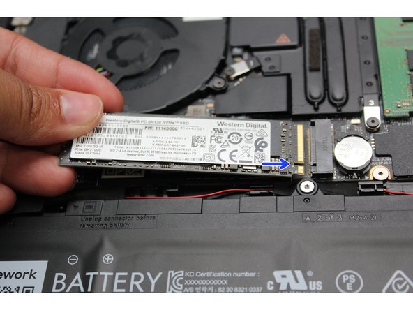
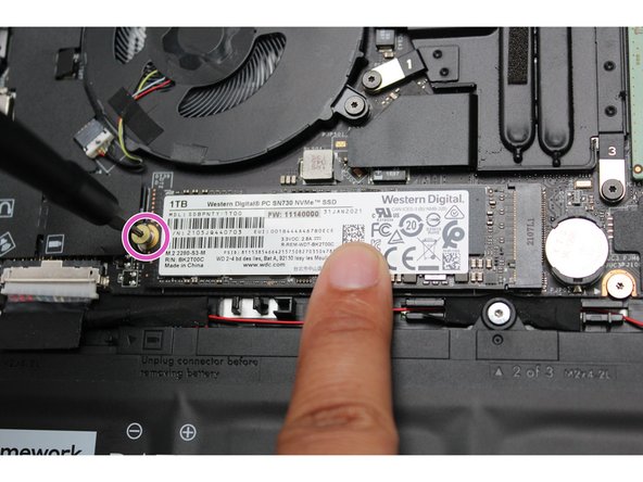
Unscrew the fastener holding down the Storage.
-
The Storage module will pop up at a 20 degree angle.
-
Slide the module out of the socket using a straight motion and remove it from the Mainboard.
-
-
-
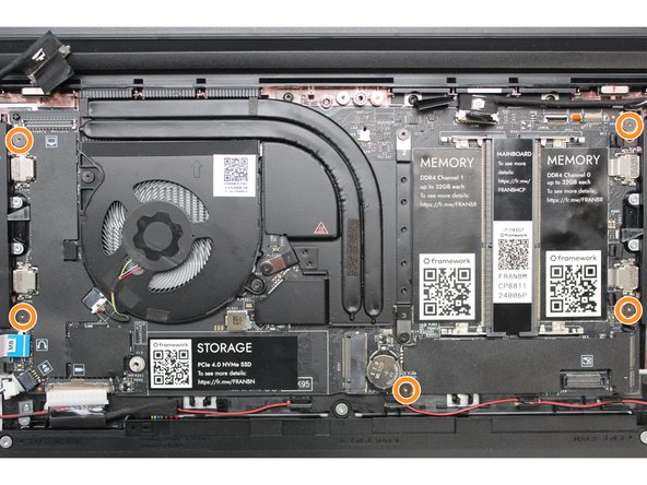
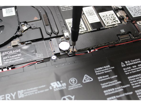
Using the T5 bit in the Framework Screwdriver, unscrew the five fasteners holding down the Mainboard.
-
These fasteners will completely come out. Be sure to keep them in a safe place during the replacement so that you do not lose them!
I had a bit of a hard time removing the fastener in the middle (next to the coin battery) on an 11th gen laptop 13.
When unscrewing it (which was harder than with the other fasteners) it would turn indefinitely without ever coming out.
I eventually got it to come out by pushing it upwards with something thin while unscrewing it.
That fastener did look different than the other ones.
Tomi Fontanilles - Resolved on Release Reply
-
-
-
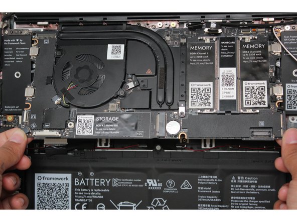
In order to lift the Mainboard off the Bottom Cover, grab it from the bottom edges and lift up very gently. There should be no resistance when lifting up the Mainboard unless a previous step was missed.
-
The components located underneath the Mainboard are highly sensitive. Be sure to handle the board by the edges, and avoid touching any components on the board.
-
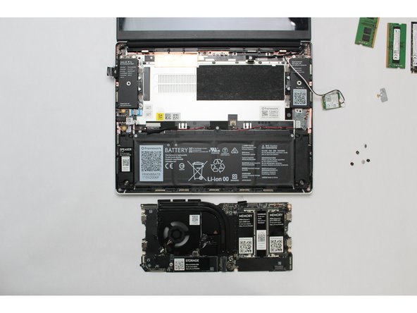
The Mainboard is now fully disconnected from the Framework Laptop.
If your new mainboard didn't come with its own, be sure to remove the RTC battery from the old one so you can install it in the new one. This needs to be mentioned in this guide.
Not exactly true! Starting from 12th gen Intel and newer boards, you are able to run the boards without the RTC battery installed. Intel 13th gen/AMD 7040 and newer boards won't ship with the RTC battery installed anymore, so there is no need to worry about replacing in the RTC battery, unless you are looking to using it as a Single Board Computer or have an 11th gen board which does need the RTC battery to boot.
Salad -
-
-
-
The easiest way to properly install the Mainboard is by aligning the two alignment pins on the Bottom Cover with the two holes on the Mainboard.
-
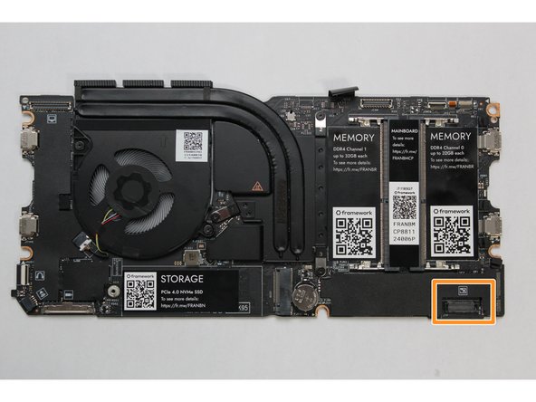
Take a close look at the actual Mainboard and you'll notice two small holes. You will see one hole on the top right and the other on the top left-hand side of the Mainboard as indicated in the first image with the orange arrows.
-
The alignment pins are located on the Bottom Cover as indicated with the green arrows in the second image.
-
Place the Mainboard on the Bottom Cover by using the alignment pins as a guide. Place the holes in the Mainboard directly over pins in the Bottom Cover. Both the left and right-hand side pins should fit into the holes perfectly.
-
The components located underneath the Mainboard are highly sensitive. Be sure to handle the board by the edges, and avoid touching any components on the board.
-
Once you have placed the Mainboard down be sure to make sure that the Speaker cable, Display cable, Camera cable, WiFi antenna cables, Audio Board cable, or the Battery cable are not stuck between the Mainboard and Bottom Cover as all the cables will need to be reconnected into their respective sockets after the Mainboard is secured in place.
Check the pins on the battery connector to be sure they are straight, before installing and screwing down the new mainboard. It's very difficult to see the pins once the board is screwed down. See step 27
Gary Aitken - Resolved on Release Reply
-
-
-
Using the T5 bit in the Framework Screwdriver, screw the five fasteners into the Mainboard once it is properly seated.
-
Be sure to not over-tighten the fasteners.
-
-
-
Using two fingers, slide the Speaker cable into the Mainboard using a straight motion and a slight amount of force.
Make sure it is pushed all the way in; it takes a fair amount of pressure to seat it. When fully seated, there will be only ~1mm between the ears on the connector and the black housing.
Gary Aitken - Resolved on Release Reply
-
-
-
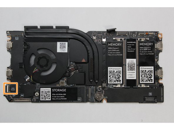
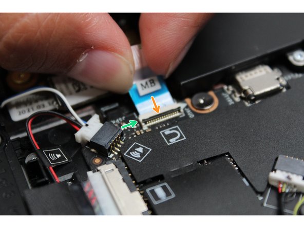
Connect the Audio Board cable by gently sliding it into the Mainboard. Make sure the black latch on the connector is flipped up so that you can slide the Audio Board Cable into the connector. Slide the cable straight in until the white line is almost at the edge of the connector
-
Using your finger or the spudger end of the Framework Screwdriver, flip the black latch down towards the Mainboard to lock the cable in place.
-
Once the black latch is secure the Audio Board cable should not come loose.
That small black bar on the white Audio Board connector is flipped up in Picture #2 (open) and flipped down in Picture #3 (closed). It wasn't clear to me just by looking that that tiny little black bit of plastic does actually articulate.
Brody Brooks - Resolved on Release Reply
-
-
-
Hold the pull tab on the Display cable and connect it into the Mainboard by aligning the pins from the cable with the socket pins on the Mainboard.
-
-
-
Hold the pull tab on the Webcam cable and connect it into the Mainboard by aligning the pins from the cable with the socket pins on the Mainboard.
-
-
-
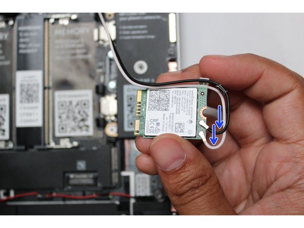
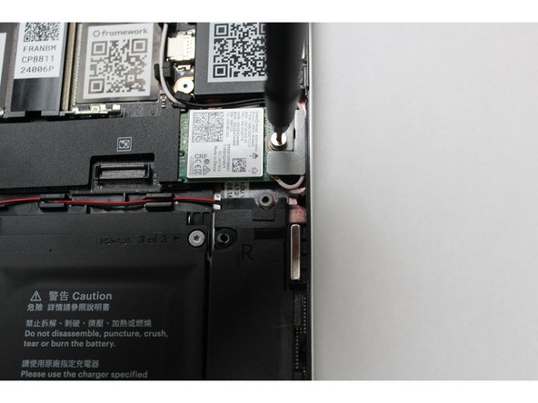
Make sure that both the black and white WiFi Antenna cables are connected to the module and are rotated downwards as indicated in the second picture with the blue arrows.
-
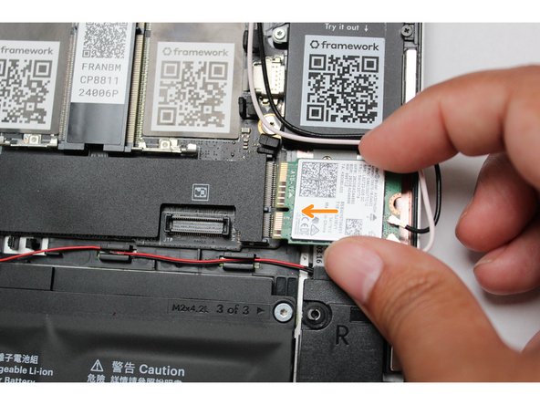
Insert the WiFi module into the Mainbord by aligning the notch on the module with the notch on the socket.
-
-
-
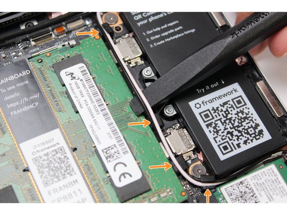
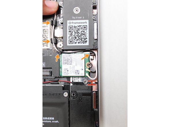
Once the module is properly inserted into the Mainboard, carefully route both the black and white WiFi Antenna cables into the black rubber routers as indicated in the first image. Place both the cables behind the metal structure located near the top right of the WiFi module as well.
-
Important: The WiFi Antenna cables should not touch the Speaker located below the module as indicated in image one.
-
Place the silver bracket over the WiFi module and place the fastener in the hole. Using the T5 bit in the Framework Screwdriver, screw the fastener into place.
-
Be sure to not over-tighten the fastener.
Be careful to align the wi-fi board properly and push/hold it all the way down. The top of it should be flush with the top of the threaded piece into which the hold-down bracket screw goes. When adding the bracket, make sure it is seated properly also -- there is a pin that sticks up that needs to go through the smaller of the two holes in the bracket.
I am a bit puzzled that the bracket is not insulated on the bottom side. It looks like it could short out the two antenna connectors if it was bent or there was pressure on top of it.
Gary Aitken - Resolved on Release Reply
This, surprisingly, was the most difficult step. I got the bracket off when removing the board, but forgot how I'd gotten it out when trying to put it back. That and the bracket in my F13 AMD 7040 series laptop looks different than the above pictures. Instructions could be clearer about how to properly install the bracket.
Brody Brooks - Resolved on Release Reply
-
-
-
Insert the Memory module into the Mainboard by aligning the notch on the Memory module with the notch on the socket.
-
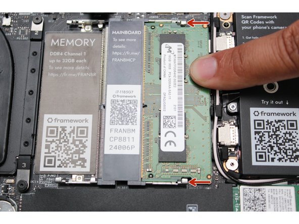
Once the module is fully inserted, it will rise up at a 20-degree angle. Gently press it down towards the Mainboard until the clips located at the top and bottom of the receptacle snap into place (see the red arrows in the third image).
-
If you are using one Memory module, place it in the right socket that is labelled “Channel 0."
-
The first boot after installing a new Memory module will take longer than normal, as the system prepares itself for the new module.
The right-side memory slot receives the module "right-side up", whereas the left-side slot receives the module "upside-down".
Alexander Ou - Open Reply
For the AMD Ryzen 7040 Series mainboard I got, there is a covering over the memory slots. According to the quick start guide for that edition: "There are black mylar sheets covering the memory slots. These can be gently bent up to insert your memory modules."
A note should be added here - I thought at first this was a protective covering I was supposed to remove.
Joe Paolicelli - Resolved on Release Reply
-
-
-
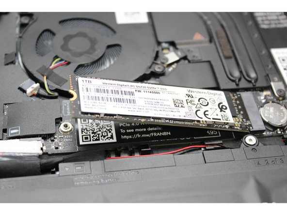
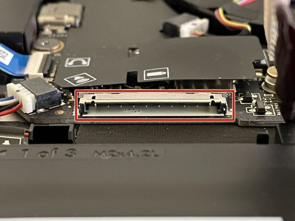
Align the notch on the Storage module with the notch on the socket and slide the module into the Mainboard.
-
Once properly inserted the module will rise up at a 20-degree angle.
-
Using one finger gently hold the Storage module down to the Mainboard and use your other hand to screw in the fastener using the T5 bit in the Framework Screwdriver.
-
Be sure to not over-tighten the fastener.
-
-
-
Before plugging the Battery connector back in, double check the pins on the Battery receptacle on the Mainboard, and make sure none of them look bent.
-
Don't plug the Battery connector in if pins look bent, as that will bend them even further. Reach out to Framework Support for guidance.
-
If you feel resistance when plugging in the Battery connector, stop, slide the connector back out, and make sure that no pins are being bent.
It would be better to check this before you even insert the new board into the chassis. It is very difficult to see the pins once the mainboard is screwed down.
Gary Aitken - Resolved on Release Reply
-
-
-
Carefully slide the Battery connector back into the mainboard, gripping both edges of the connector and sliding in straight without letting the connector twist or bend.
-
The LEDs on the Mainboard may flash red when the battery is plugged in for a short while. This just indicates that the Mainboard has regained power while the Input Cover is off. You can safely continue on to the next steps.
If your mainboard power pins are straight, and the force required to insert the connector is too high to gently insert the battery connector, I found applying a TINY amount of dielectric grease to the tip of a sim card remover, then rubbing the grease directly onto the mainboard pins allowed it to insert. I only needed a tiny amount of grease, it was almost not visible to the naked eye, however this allowed the battery connector to insert into the mainboard connector without using a force that felt it was about to break the mainboard connector.
Joss Malasuk - Resolved on Release Reply
We don’t recommend putting grease on the pins, as it could increase electrical resistance and cause other issues.
-
-
-
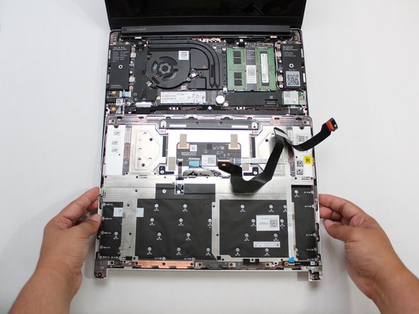
Gently place the Input Cover keyboard side down on the Bottom Cover as indicated on the image. The cover should be about an inch and a half away from the bottom of the Mainboard so that you can comfortably install the Touchpad Cable.
-
Note: The orientation of the Input Cover matters. Study the first image in this step to ensure you are properly attaching the cover.
-
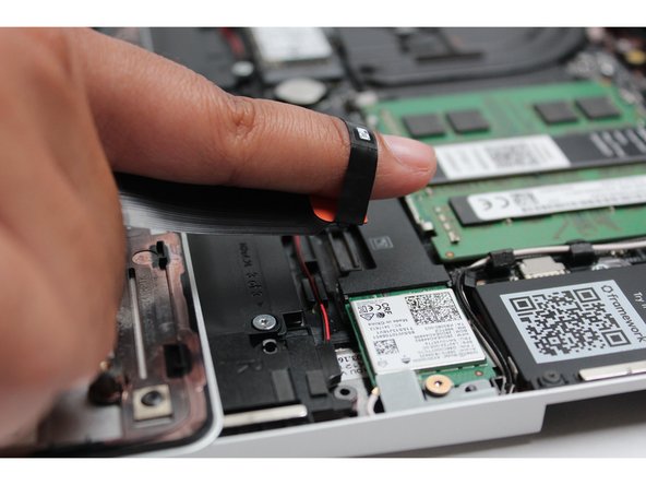
Locate the loop on the end of the Touchpad Cable and insert your finger into it.
-
-
-
Using slight force, connect the Touchpad Cable by aligning it to the socket on Mainboard. You should hear it click into place once properly connected.
-
-
-
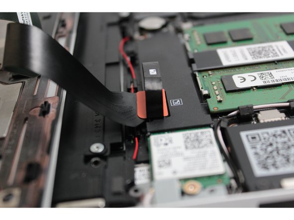
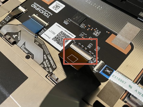
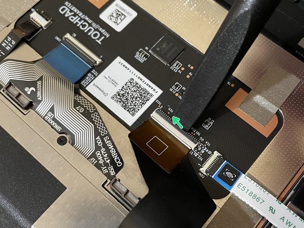
Before closing up the laptop, make sure that the Touchpad end of the Touchpad Cable is fully seated in the receptacle.
-
The cable should be inserted far enough that the white line almost touches the receptacle.
-
If it is not inserted far enough, you'll need to flip up the black latch on the other side of the connector, slide the cable in further, and then close the black latch again.
-
-
-
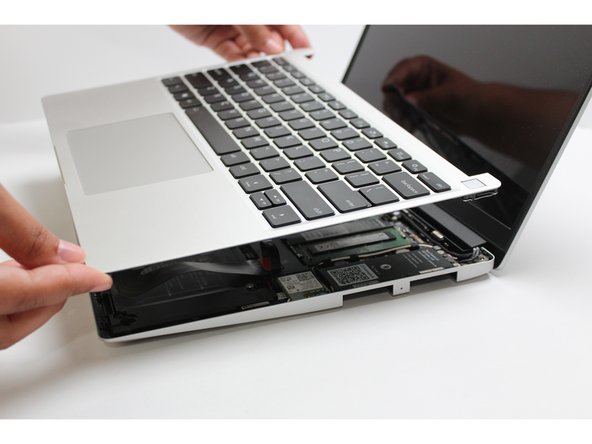
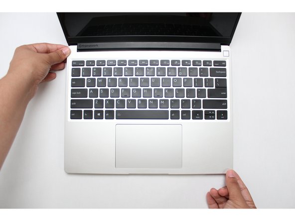
Once the Touchpad cable is secured to the Mainboard, flip the Input Cover over the Bottom Cover so that the keyboard is facing up and attach it to the Bottom Cover by aligning the top and bottom edges of both covers.
-
Tip: The covers are magnetic and should fit into one another easily. If you feel any resistance simply lift the Input Cover up and try again.
-
-
-
Close the Framework Laptop and turn it upside down to reveal the empty Expansion Card bays and fasteners on the Bottom Cover.
-
Using the T5 bit in the Framework Screwdriver, screw all 5 fasteners back into the Bottom Cover.
-
Be sure to not over-tighten the fasteners.
You should re-install your expansion cards at this point. It's a step missing from these instructions.
Gary Aitken - Resolved on Release Reply
-
-
-
Insert the Expansion Cards of your choice into any of the empty bays.
-
Plug the USB-C power cable into the USB-C Expansion Card.
-
Turn the Framework Laptop over, open it, and press the power button. If you're using Windows, you may need to re-activate Windows after you replace the Mainboard.
-
The first boot will take longer than normal as the system does memory training. The more memory you've installed, the longer this could take (on the order of a minute or two with 64GB!)
If you are upgrading to an Intel Ultra series, install windows as a fresh installation. Backup all files first.
Jim Barron - Open Reply
-
-
-
If you're using Windows and you've upgraded to a new Mainboard generation, you'll also need to install the latest Framework Laptop Driver Bundle. We also recommend installing the latest BIOS version for your Mainboard, downloadable from the same page.
-


- To purchase a Framework Laptop visit the Framework website
- Want to learn more about the Framework Laptop? Take a look at our blog
- If you have any questions or concerns, feel free to reach out to Framework Support
- To purchase a Framework Laptop visit the Framework website
- Want to learn more about the Framework Laptop? Take a look at our blog
- If you have any questions or concerns, feel free to reach out to Framework Support
Cancel: I did not complete this guide.
28 other people completed this guide.
11 Comments
Successfully went through that with a gen 13 Intel mainboard.
I use Debian Linux, and I had to reinstall the boot loader so that the new mainboard would accept the previous NVMe as bootable. Not sure whether there is an easier procedure, but I resorted to GrubEFIReinstall - Debian Wiki.
Greate guide overall, I do have one small note to give. When upgrading from the 11th gen Intel mainboard to the 13th gen intel mainboard, there is not a CMOS battery provided with the 13th gen board (from my research that is because it is not needed) but the pictures of the board being upgraded to has the CMOS battery included with it. Since the guide didn't include a note about it, I did move that battery over as well which is tricky to get that battery out of the original board. I would recommend maybe added a new note that the newer gen boards may not have nor need a CMOS battery, so people not out unneeded stress on the old board trying to get the battery out. Keep up the great work.
Matthew Watson - Resolved on Release Reply
Very simple to follow. Great guide that made my replacement simple. My only feedback is to maybe include a good picture of the display cable. Mine came out a bit further from the display and it was tricky figuring out where it went back in. Maybe a step after 28 showing the display bezel going back on would be a good place for that.
Nathan Michalik - Resolved on Release Reply
Is there a reason the battery is plugged in first upon reassembly? Usually the battery should be plugged in last in my experience.
Nope, no good reason. The assembly can be done safely with the battery connected, but there is also no reason for it to be first.
This guide is great. I’ve replaced the input board on a Macbook Pro (successfully I might add), and I can’t even imagine what replacing the mainboard on one must be like. This is nuthin’ - it took me about 30 minutes because I like to be super careful but it’s really easy.
I haven’t got a framework laptop yet but I wanted to check how thorough the guides for replacing parts are and after reading this one I can say I am very impressed and relieved! My fear when messing with electronics is that it won’t be easy to put it back together but this gives you all the steps from start to finish. They don’t assume that you just know (or should know) stuff which is great. It feels me with confidence that replacing something on my own will be just a matter of “oh how long will that take me” and not “oh I am not sure I can do it without breaking it“. Really looking forward to buying one when it is available in the UK.
Konstantinos Efthymiou - Resolved on Release Reply
If you are upgrading to an Intel Ultra series, disable Bitlocker before shutting down your old main board if you are upgrading to an Intel Ultra series.
And for Ultra series, install windows as a fresh installation. This appears to be particularly important if you can't disable Bitlocker because your old main board died.
Jim Barron - Open Reply
Before even starting, inspect the new board to be sure all the connectors are ok. Mine had the speaker connector broken off.
Gary Aitken - Resolved on Release Reply
@ahappykittycat I wish that I had read your comment before I undertook this…
Mike Shaver - Resolved on Release Reply
IMPORTANT: If you plan to install your existing mainboard in a CoolerMaster case, make sure to boot into the BIOS and enable standalone mode before continuing.
Richard Tango-Lowy - Resolved on Release Reply
Pretty sure you might want to include a reminder to backup the bitlocker recovery key if it is enabled. The system will definitely boot to the bitlocker recovery screen since it will be a different TPM.
James Wu - Resolved on Release Reply
It could be helpful to give the bash terminal command to shutdown such as
Patrick Corey - Resolved on Release Reply
Bottom left*
Vijfhoek - Resolved on Release Reply