
Introduction
You can also follow this guide if you want to re-paste (apply new thermal paste) your Framework Laptop. However, we don’t necessarily recommend doing that unless needed, since this operation requires exposing and handling the bare CPU die, which is somewhat delicate.
Make sure to follow the steps in this guide carefully, including unscrewing and rescrewing the fasteners in the right order on the heatsink and fan.
Tools
Parts
-
-
Power off the Framework Laptop by navigating to the Windows icon on the bottom left and clicking on "Power" followed by "Shut down," or if on Linux, the equivalent action there.
-
-
-
Unplug your power cable from the USB-C Expansion Card in your Framework Laptop.
(I had formerly left a long comment here about how you guys 'forgot' to have a bit about removing the expansion cards...and while some official guide on this is probably a good idea to have, it's...not actually necessary to remove them! Even though in the build guide, they go in last, they don't actually need to come out in order to replace the screen! Heh.)
-
-
-
Close the lid on your Framework Laptop and place it upside down on a soft, non-marring surface, such as the bag that it shipped in.
-
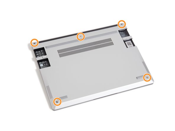
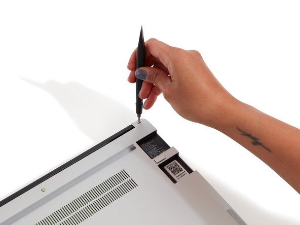
Using the T5 bit in the Framework Screwdriver, unscrew the 5 fasteners on the Bottom Cover. These fasteners will remain attached in the Bottom Cover so that you do not lose them.
-
The fastener on the bottom left (circled in red) will not unscrew as far as the others, as it is acting as a lifter for the Input Cover.
-
You'll hear this fastener start clicking as you rotate when it is unscrewed far enough.
-
Do not use a powered tool for these steps, as this will likely result in damage to the fasteners.
It would be super nice if the lower-left screw were circled in red as the text indicates!
Mike Shaver - Resolved on Release Reply
Thank you for writing the specific detail on the lower left corner screw.
I thought something was not working correct until re-read this guide.
Patrick Corey - Resolved on Release Reply
-
-
-
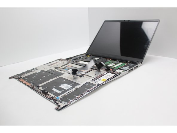
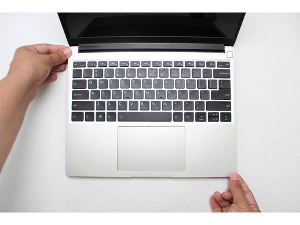
Flip the Framework Laptop back over and open the lid to around 120 degrees.
-
Important: Pull the Input Cover off carefully as it is still attached to the Mainboard via the Touchpad Cable. You don't need to disconnect this cable to do most repairs. You can just flip the Input Cover over. If you do want to disconnect it though, make sure to disconnect the Mainboard side using the finger loop over the orange label.
-
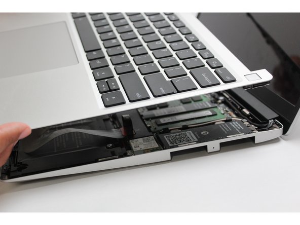
The bottom right corner of the Input Cover lifts up when the five fasteners are properly unscrewed from the previous step. You should not have to use any excessive force to remove the Input Cover.
-
Carefully lift the cover up from the bottom right corner. If you need to, you can use the spudger end of the Framework Screwdriver to lift it as well. Lift the Input Cover off the Mainboard, flip it over (keyboard side down), and place it about halfway on the Bottom Cover.
-
Be sure not to put too much force on the Touchpad Cable when doing this.
-
If the LEDs on the left and right sides of the system are flashing red when you lift off the cover, it means the system is still powered on. Make sure your power cable isn't plugged in and that you have shut down correctly.
-
Note that it may take up to 30 seconds after shutting down for the system to fully power off. Wait until the LEDs stop flashing before proceeding.
-
You should keep the Battery connector plugged in unless you need to replace the Battery, Mainboard, or Speakers. This connector is easy to accidentally damage, so it's better to not handle it.
Important: Pull the Input Cover off carefully as it is still attached to the Mainboard via the Touchpad Cable. You don't need to disconnect this cable to do most repairs. You can just flip the Input Cover over. If you do want to disconnect it though, make sure to disconnect the Mainboard side using the finger loop over the orange label.
While that’s true for most repairs, it’s pretty much essential to disconnect that cable for this repair, so I think the guide should probably amend this boilerplate!
Mike Shaver - Resolved on Release Reply
I can verify that this claim is TRUE, see the "Found out unscrewing stuff on a non-flat surface is a bad idea" section of my recording How NOT to do a Framework Laptop 13 keyboard replacement.
You should flip the keyboard around the x-axis (so that the back edge comes towards you as you flip) and not the z-axis (resulting in the left edge rotating to the right). I started to do the z-axis and the touchpad cable was getting twisted. I am capable of messing up all instructions. This is my anti-super-power... or joker power in the Wild Cards universe.
-
-
-
Warning: Make sure the Framework Laptop has been powered off for at least 5 minutes prior to Heat Sink and Fan removal. This component can be extremely hot.
-
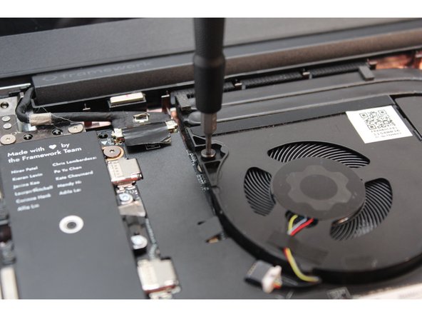
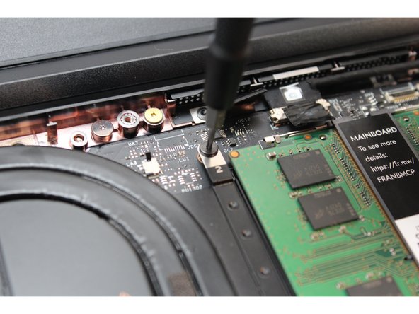
Using the Framework T5 bit in the Framework Screwdriver, unscrew the two fasteners on the Fan first.
-
-
-
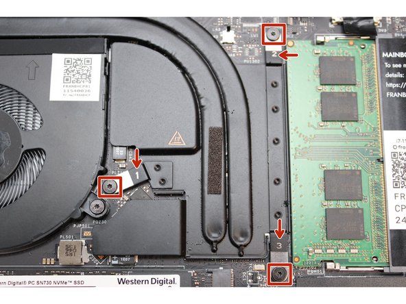
Next, unscrew the fasteners labeled 3, then 2, then 1 (in this order).
-
The screws will come loose after a few revolutions, they will remain captive (attached) in the fan.
-
-
-
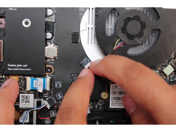
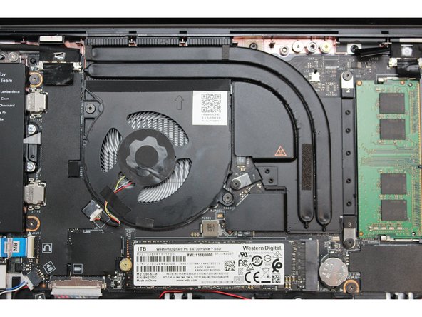
Gently lift up the Heat Sink and Fan module and move it over slightly so that you can unplug the power cable. The thermal paste may be holding the module in place, you may have to apply a slight rotating motion to break the hold of the grease.
-
Using your fingernail, disconnect the Fan cable from the Mainboard by sliding it straight out.
-
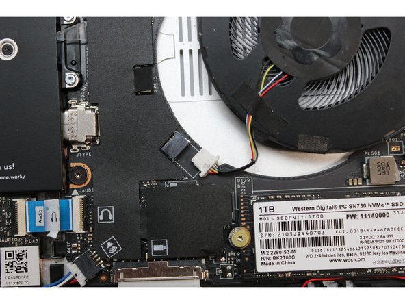
The Heat Sink and Fan component is now fully detached.
-
-
-
Before installing a brand new Heatsink and Fan module, be sure to carefully wipe off the excess thermal paste from the CPU using a clean, lint-free tissue, cloth, or cotton swab. The new module has new thermal paste on it.
-
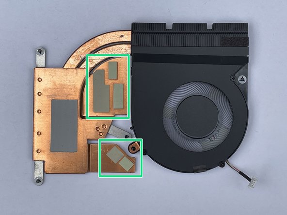
Look for any thermal pads that might have remained stuck on the Mainboard. They are light in color and very soft to the touch. If you notice any, gently peel them off.
-
Also make sure all of the thermal pads are properly in place in the new Heatsink. If a thermal pad is missing, there is risk of power regulators overheating.
This is not what the module looks like for my device (FW 13 AMD 7040).
It does not have any thermal pads (or the parts they're stuck to).
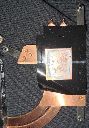
But it does have black plastic foil on the part that goes on the CPU, except where the thermal grease is - I don't know if it is important or not, the original part in my laptop had it (see image), but the image used to illustrate this step doesn't.
As others mention, it also has a protective cover over the thermal grease (made of clear plastic), which can leave residues of its glue on that plastic foil.
If it turns out the black plastic foil isn't needed pulling it off would be the easiest way to get rid of that glue from the thermal grease cover..
What I'm saying is: All these parts should be mentioned and it should be documented if they're needed or not and what cleaning has to be done to them, if any.
Daniel Gibson - Open Reply
If you want us to check that all the pads are in place on the new unit, you should tell us how many there are and where to look.
I see two nearly square, and 2 long rectangles, one very thin and the other think like the first two.
Neal McBurnett - Open Reply
I got water in my system while powered off. Took the whole thing apart, including removing heat sink and need to replace the thermal pad.
Is there a thickness spec to aim for, for a replacement thermal pad?
Michael Mangum - Open Reply
Make sure to remove the protective plastic from the thermal pads and the plastic enclosure over the thermal paste.
Also there was some adhesive residue leftover when I removed the cover over the thermal paste, not sure how vigorously that should be cleaned off. Could be something to address here as well
-
-
-
Place the Heatsink and Fan module on the Mainboard aligning it carefully with the processor.
-
The new module comes with thermal paste so there is no need to any additional paste.
-
Make sure that the white or pink thermal pads stay in the spots they were originally on on the heatsink, and if any stayed stuck to the mainboard from the old heatsink, peel those off to avoid doubling them up.
This section needs to add guidance for users who are not installing new modules with pre-applied thermal paste (i.e. for users who are re-seating the module, you will need to clean the processor and heatsink with isopropyl alcohol and then apply a small amount of thermal paste on top of the processor before re-placing the heatsink/fan module).
-
-
-
Check the plug for the Fan, and note that there is a black dot on one side. The black dot should face upwards away from the Mainboard. With the black dot facing upwards, plug the cable back into the Mainboard by sliding it straight into the receptacle.
-
Make sure the plug is in the right orientation. Inserting it upside down can permanently damage the receptacle.
-
Starting with the fastener slot marked 1 on the Heatsink, start screwing the fasteners back into place using the T5 bit in the Framework Screwdriver. Next fasten number 2, followed by 3.
-
Be sure to not over tighten the fasteners.
-
Screw the two fasteners on the Fan back into place.
-
Be sure to not over tighten the fasteners.
-
The Heatsink and Fan module is now fully installed.
I think I might have screwed up the plug in on the power supply during this step :/ I tried seating it with a normal amount of pressure (just with my finger, guiding it with some thin-tipped tweezers), and it wasn't turning on when I finished up and closed up my laptop. So I then used some more pressure to get it seated normally, but it still didn't turn on. I tried a few more ways of plugging it in and out, making sure the pins are aligned, but no dice.
I even tried putting the old fan assembly back in (it wasn't completely broken, just having noise/efficiency issues), but the old assembly no longer turns on either.
Not sure how to proceed. Trying to troubleshoot how to fix the fan port :/
Daniel Podlovics - Resolved on Release Reply
As many new (and experienced..) computer/device diy/modders/builders can (..often..) manage to (easily) strip fasteners and/or their mount points, I suggest including a fixed torque screwdriver(s). A universal/standardized torque req for all mount points would also be a pretty neat (marketable) 'innovation' for a DIY computer. If not feasible, maybe standardize to 2 or 3 torque values and include those drivers.
-
-
-
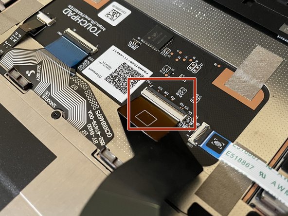
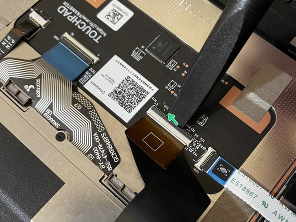
Before closing up the laptop, make sure that the Touchpad end of the Touchpad Cable is fully seated in the receptacle.
-
The cable should be inserted far enough that the white line almost touches the receptacle.
-
If it is not inserted far enough, you'll need to flip up the black latch on the other side of the connector, slide the cable in further, and then close the black latch again.
-
-
-
Flip the Input Cover over the Bottom Cover so that the keyboard is facing up and attach it to the Bottom Cover by aligning the top and bottom edges of both covers.
-
Tip: The covers are magnetic and should fit into one another easily. If you feel any resistance simply lift the Input Cover up and try again.
-
-
-
Close the Framework Laptop and turn it upside down to reveal the five fasteners on the Bottom Cover.
-
Using the T5 bit in the Framework Screwdriver, screw all 5 fasteners back into the Bottom Cover.
-
Be sure to not over-tighten the fasteners.
-


- To purchase a Framework Laptop visit the Framework website
- Want to learn more about the Framework Laptop? Take a look at our blog
- If you have any questions or concerns, feel free to reach out to Framework Support
- To purchase a Framework Laptop visit the Framework website
- Want to learn more about the Framework Laptop? Take a look at our blog
- If you have any questions or concerns, feel free to reach out to Framework Support
Cancel: I did not complete this guide.
20 other people completed this guide.
8 Comments
Going to post this for whomever needs this in the future. DO NOT OVER TIGHTEN THE SCREWS. I followed the steps in this guide. Took 5 minutes. All was good and then my laptop started overheating so badly that I had to take the whole thing apart again and re-apply the thermal paste. Turns out I tightened the screws way too much and it pushed out the thermal paste (my guess of course, but it's running fine now). As soon as you feel that the screws don't move anymore, just stop turning. Learned the hard way. Don't repeat my mistake. A word of caution on top of the article for people who don't work on the internals of computers every day would probably do wonders.
My laptop had been overheating for a long time, even after I replaced the thermal paste. It had also become quite noisy over the past few months. I finally decided to invest in this new module, and it made a huge difference! The temperature is now much lower, and the fan is significantly quieter, even compared to the original version that came with the laptop.
I think I might have screwed up the plug in on the power supply during this step :/ I tried seating it with a normal amount of pressure (just with my finger, guiding it with some thin-tipped tweezers), and it wasn't turning on when I finished up and closed up my laptop. So I then used some more pressure to get it seated normally, but it still didn't turn on. I tried a few more ways of plugging it in and out, making sure the pins are aligned, but no dice.
I even tried putting the old fan assembly back in (it wasn't completely broken, just having noise/efficiency issues), but the old assembly no longer turns on either.
Not sure how to proceed. Trying to troubleshoot how to fix the fan port :/
Daniel Podlovics - Resolved on Release Reply
Sorry for nitpicking, but is there a reason why the screws for the fans are +, while those of the CPU heat sink are * ?
Given the high likelihood that they both have to be removed at the same time, might as well use the same type of screws ?
It is easy to work on either the fan or the CPU heat sink, then forget to switch the driver head, which can lead to threading, especially when using the + head on the * screws.
Rousslan Dossa - Resolved on Release Reply
I did this and it took less than 5 minutes. The new fan/heatsink assembly does feed heavier and more robust than the old one (which was making a nasty broken ball bearing like noise) and now it's so much quieter I want to cry
Mir Rodriguez - Resolved on Release Reply
Shouldn’t this have the marketplace link to the heatsink & fan assembly?
Katherine Reynolds - Resolved on Release Reply
If you are upgrading to an Intel Ultra series, disable Bitlocker before shutting down your old main board if you are upgrading to an Intel Ultra series.
And for Ultra series, install windows as a fresh installation. This appears to be particularly important if you can't disable Bitlocker because your old main board died.
Jim Barron - Open Reply
Before even starting, inspect the new board to be sure all the connectors are ok. Mine had the speaker connector broken off.
Gary Aitken - Resolved on Release Reply
@ahappykittycat I wish that I had read your comment before I undertook this…
Mike Shaver - Resolved on Release Reply
IMPORTANT: If you plan to install your existing mainboard in a CoolerMaster case, make sure to boot into the BIOS and enable standalone mode before continuing.
Richard Tango-Lowy - Resolved on Release Reply
Pretty sure you might want to include a reminder to backup the bitlocker recovery key if it is enabled. The system will definitely boot to the bitlocker recovery screen since it will be a different TPM.
James Wu - Resolved on Release Reply
It could be helpful to give the bash terminal command to shutdown such as
Patrick Corey - Resolved on Release Reply
Bottom left*
Vijfhoek - Resolved on Release Reply