
Introduction
Before getting started it is a good idea to make sure you have everything you need. To get started with the Cooler Master Mainboard Case you will need:
- Framework Laptop 13 Mainboard (any generation is compatible)
- Before using the Mainboard outside of a Framework Laptop make sure you are on the latest BIOS and that Standalone mode has been enabled in the BIOS.
- If you don't have an RTC battery installed (like on 13th Gen or Ryzen 7040 Series) and you want to preserve the system clock after disconnecting power, you will be able to pick up an RTC battery in the Marketplace soon. The steps to remove and install the RTC cell can be found in this guide.
- Framework Screwdriver or any screwdriver with a T5 bit
If you wish to install WiFi you will need:
- a compatible M.2 WiFi Card
- Framework Laptop 13 Antenna or SMA antennas with a SMA to U.FL/MHF4 cables
To install the Audio board you will need:
- Framework Laptop 13 Audio Board
If you don't wish to install WiFi in the case, you can skip steps 2-4 as well as step 6. If you don't intend to install an Audio Board you can skip steps 7 and 8.
-
-
Included in the box you will find the following:
-
Rubber Stand for standing the case upright on your desk (optional)
-
The Mainboard case with 8 T5 fasteners preinstalled.
-
WiFi bracket for mounting the WiFi card (optional)
-
3 smaller fasteners for the WiFi bracket and Audio Board (optional)
-
4 VESA screws to mount the case on a 100mm x 100mm VESA bracket (These are included inside of the Rubber Stand as pictured)
-
-
-
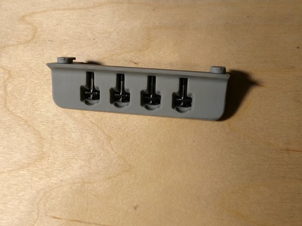
Remove these 8 fasteners and set them aside. If this is your first time assembling the case these fasteners will be preinstalled.
-
With the fasteners removed the top and bottom of the case should pull apart with little force.
-
If the top and bottom are not easily separated make sure that all 8 fasteners are removed and that no Expansion Cards are installed currently.
-
-
-
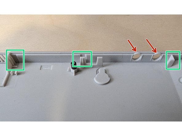
If you are using the Framework Laptop Antenna this will fit into the guides highlighted in green.
-
The Framework Laptop Antenna is fixed to the bottom of the case as shown in the second image.
-
If you are using SMA Antennae these can be fitted into the holes highlighted in red
-
-
-
The cables connecting the antenna to the WiFi Card are routed under the Mainboard and should be fitted into the cable guides.
-
If you are having difficulty fitting the antenna cables into the guides, you can carefully use the spudger end of the Framework Screwdriver to push the cables into place.
-
-
-
Connect the black and white WiFi Antennas into their respective sockets on the module. You can see a little triangular indicator on the module's label pointing out which color goes where. Make sure to align them well before applying force to click them into place, as the connectors are small and fragile.
-
For a video on how to attach these connectors, check this out.
-
-
-
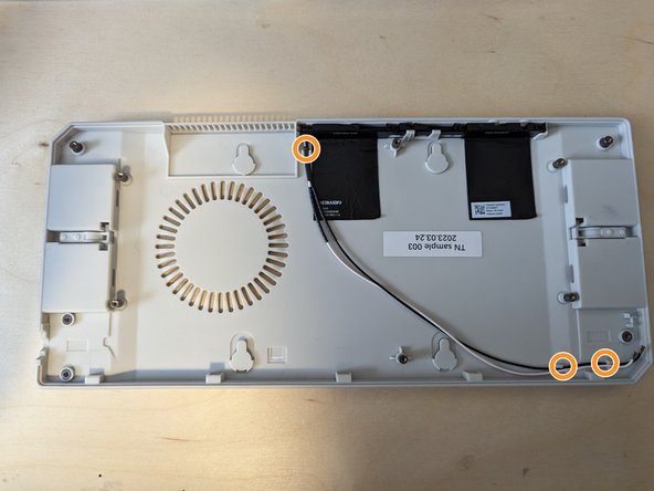
Lifting it carefully from the edges, align the holes on the Mainboard with the posts outlined in orange and place the Mainboard into the case.
-
There are no fasteners to tighten at this stage.
-
-
-
Insert the WiFi card into the WiFi socket on the Mainboard and use the WiFi bracket to secure it in place.
-
If you are using the metal WiFi bracket that came with the case, you can align it using the post highlighted in orange. Using one of the three smaller fasteners that are included with the case.
-
If using the newer plastic WiFi bracket fits onto the card for alignment and includes the fastener in the bracket.
-
-
-
Using two of the three included PCB fasteners, install the Audio Board in the lower left of the case.
-
-
-
Using your fingernail or the spudger end of the Framework Screwdriver, flip up the black latch on the connector.
-
Slide the cable in until the white line is almost at the edge of the connector.
-
Flip the black latch down to secure the cable in place.
-
-
-
Before closing the case, it's a good idea to make sure that Storage and Memory are installed.
-
For guidance on installing storage please see Step 6 of the storage guide here.
-
For Memory please see Step 6 of the Memory guide here.
-
Now that all of the internal components are installed, you can close the case by tightening these 8 fasteners.
-
Do not over tighten these fasteners, once you feel resistance they are tight enough.
-
-
-
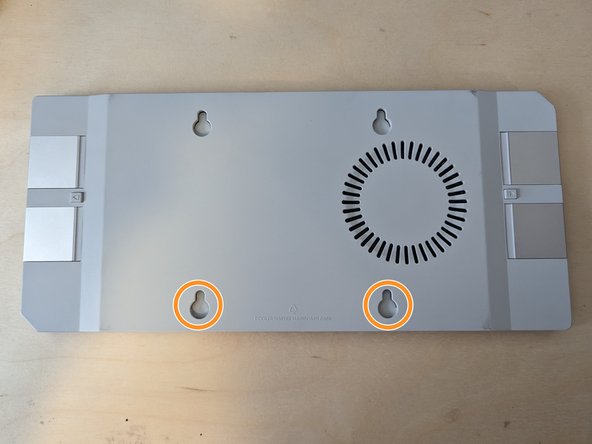
Included in the box with the Cooler Master case is an optional rubber desk stand which simply pushes into the bottom two holes on the rear of the case.
-
In the bottom of this rubber desk stand you will also find 4 bolts which can be used to attach the case to a VESA 100mm x 100mm bracket (for example on the rear of your monitor)
-
-
-
Expansion Cards are installed and removed in much the same way as the Framework Laptop.
-
We recommend at least one USB-C Expansion Card for power, but the rest is up to you!
-
-
-
The Framework Laptop normally augments power from the power adapter with power from the Battery. Since the Battery isn’t connected when using the Cooler Master Mainboard Case, you can maximize performance by using higher power adapters supporting up to 100W. We recommend using a minimum of a 60W adapter, like the Framework Laptop Power Adapter.
-
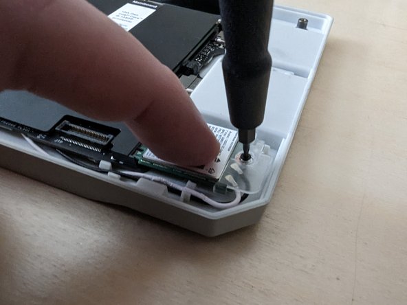
After connecting power and any peripherals, you can power on the Mainboard using this button located next to one of the fasteners and highlighted in orange on the case.
-


Cancel: I did not complete this guide.
11 other people completed this guide.
13 Comments
Boy, this has been an exercise in frustration. I've finally gotten the thing to boot in standalone mode, but oddly, I cannot get the power button on the Cooler Master case to work. The only way I can actually get the thing to start is to remove the top cover and push that little tiny switch inside. I can never get it to power on using the power switch. Anyone got any idea what's going on?
Anyone with concerns over using the AMD 7040 series as a standalone might take some comfort in knowing that when you first boot it up, it will prompt you to enter standalone mode. Judging by past comments, this seems like a newer addition where people used to struggle to get into the bios to even change that setting.
I did struggle getting the AMD drivers to install though. I had to do a few cycles of removing/re-installing them. Ultimately, installing directly from the AMD product section (not auto-discovery) worked for me.
I'm also getting a lot of TMP alarms in Windows 11 event viewer. I ordered a RTC battery to see if that makes a difference. For now, I just disabled device encryption. I'll reply to this post with more details at a later date.
Nathan Michalik - Resolved on Release Reply
-Before using the Mainboard outside of a Framework Laptop make sure you are on the latest BIOS and that Standalone mode has been enabled in the BIOS.
Is there a way to do this after its been installed on the Cooler Master Case? I had upgraded my main board but did not change the BIOS settings of this before I removed it. Just wondering if there is an easier way to enable standalone mode on this old board without having to put it back into my laptop?
Thanks
Yusuf Abdulhussein - Resolved on Release Reply
Unable to enable the Standalone Mode in the BIOS, since I purchased the AMD Mainboard and the case and the mainboard will not boot up. Also, cannot add an RTC batter since there isn't a socket for a battery. Unsure how to proceed.
Symptoms: the LEDs at either end flash blue and amber. LEDs will flash green a few times when doing different power on methods (hold pwer button, pull power). No POST is seen on the HDMI or DP outputs (using the USB-C dongles).
Steps Taken: Removed RAM and SSD, no change to symptoms. Let mainboard soak for 24 hours while connected to power. Used alternate power adapters (60 W and 100 W). Pressed/Held power button for 30 seconds.
Kevin Miller - Resolved on Release Reply
Does the Framework Laptop 13 (AMD Ryzen 7040 Series) include a RTC/CMOS battery on the mainboard?
Followed by:
[RESOLVED Mainboard Standalone w/o Framework Laptop (AMD 7040; 5 7640U) - Community Support - Framework Community]
Michael -