
Introduction
Here it is, the Framework Laptop Bottom Cover replacement guide! Before you proceed with the Bottom Cover replacement, here is a helpful tip: we recommend that you store each fastener in a dedicated space (such as a cup) as you are removing them. It is important to not mix up or lose any fasteners.
If you have questions or run into any issues, check out the Support pages.
Tools
Parts
No parts specified.
-
-
Power off the Framework Laptop by navigating to the Windows icon on the bottom left and clicking on "Power" followed by "Shut down," or if on Linux, the equivalent action there.
-
-
-
Unplug your power cable from the USB-C Expansion Card in your Framework Laptop.
-
-
-
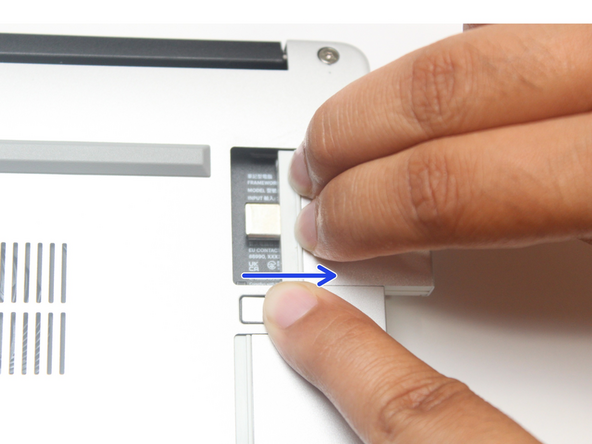
Close your laptop completely and turn it over so you can access the Expansion Cards.
-
While keeping the release button pressed, use your other fingers to slide the Expansion Card away from the laptop.
-
Important: You may have to use a little bit of force to fully disconnect the Expansion Card.
-
Make sure each Expansion Card is fully removed before proceeding to the next step.
-
-
-
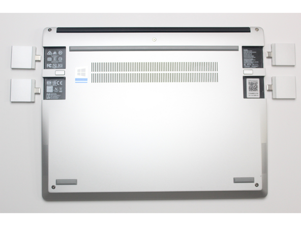
Close the lid on your Framework Laptop and place it upside down on a soft, non-marring surface, such as the bag that it shipped in.
-
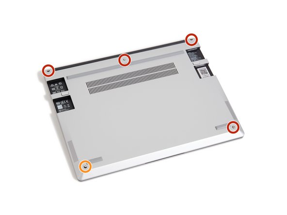
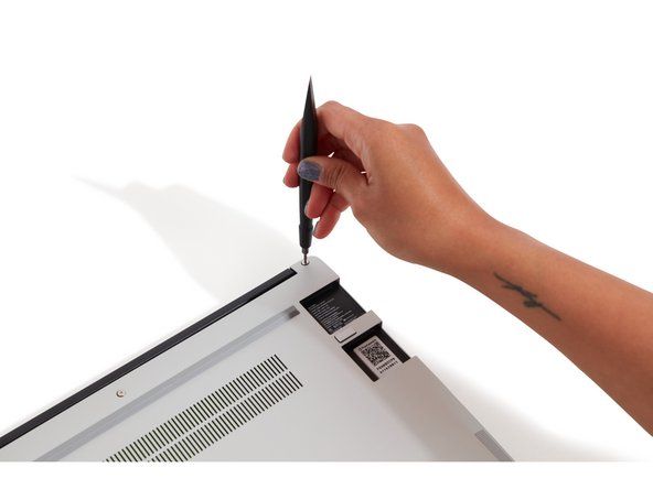
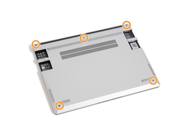
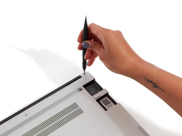
Using the T5 bit in the Framework Screwdriver, unscrew the 5 fasteners on the Bottom Cover. These fasteners will remain attached in the Bottom Cover so that you do not lose them.
-
The fastener on the bottom left (circled in orange) will not unscrew as far as the others, as it is acting as a lifter for the Input Cover.
-
You'll hear this fastener start clicking as you rotate when it is unscrewed far enough.
-
-
-
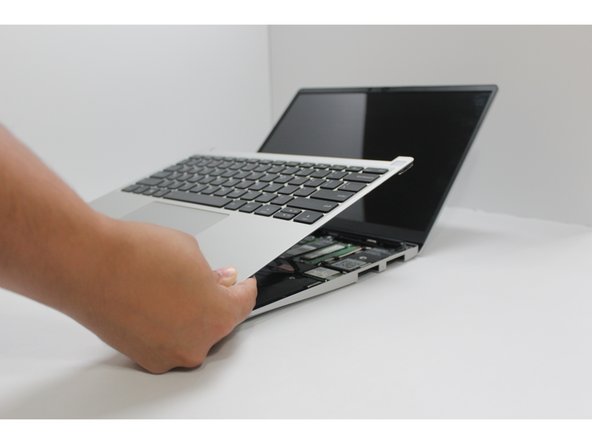
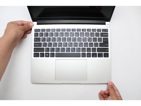
Flip the Framework Laptop back over and open the lid to around 120 degrees.
-
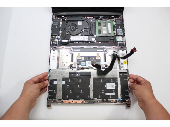
Important: Pull the Input Cover off carefully as it is still attached to the Mainboard via the Touchpad Cable. You don't need to disconnect this cable to do most repairs. You can just flip the Input Cover over. If you do want to disconnect it though, make sure to disconnect the Mainboard side using the finger loop over the orange label.
-
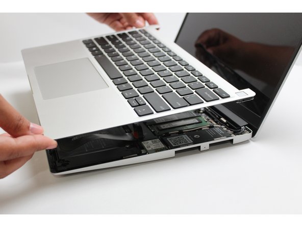
The bottom right corner of the Input Cover lifts up when the five fasteners are properly unscrewed from the previous step. You should not have to use any excessive force to remove the Input Cover.
-
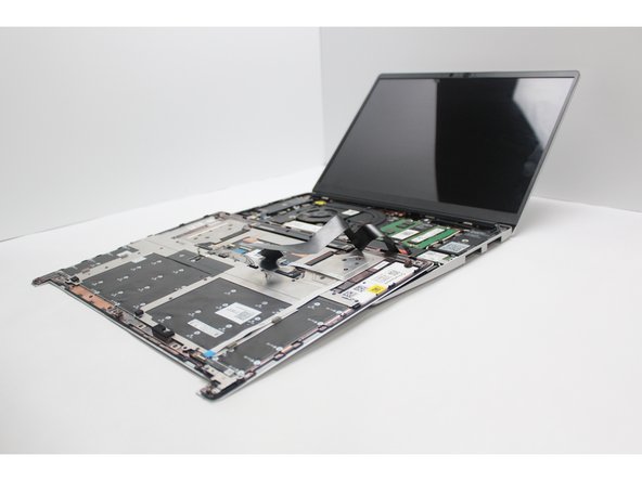
Carefully lift the cover up from the bottom right corner. If you need to, you can use the spudger end of the Framework Screwdriver to lift it as well. Lift the Input Cover off the Mainboard, flip it over (keyboard side down), and place it about halfway on the Bottom Cover.
-
Be sure not to put too much force on the Touchpad Cable when doing this.
-
If the LEDs on the left and right sides of the system are flashing red when you lift off the cover, it means the system is still powered on. Make sure your power cable isn't plugged in and that you have shut down correctly.
-
Note that it may take up to 30 seconds after shutting down for the system to fully power off. Wait until the LEDs stop flashing before proceeding.
-
-
-
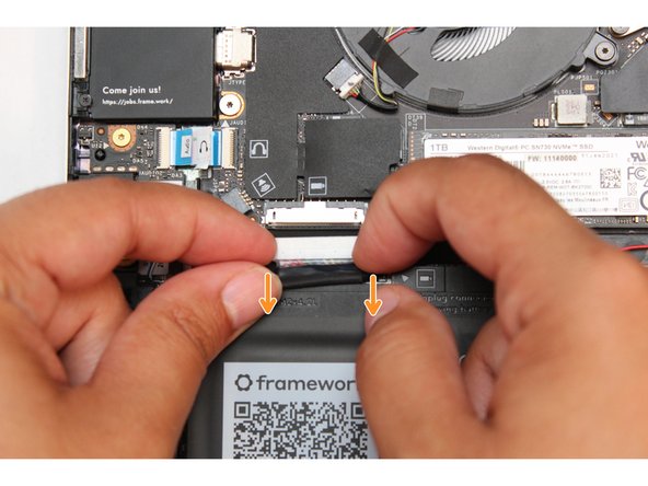
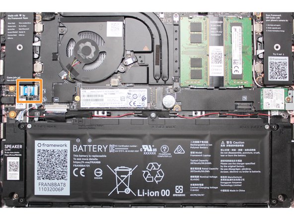
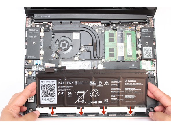
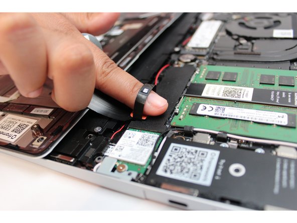
Unplug the Framework Laptop Battery.
-
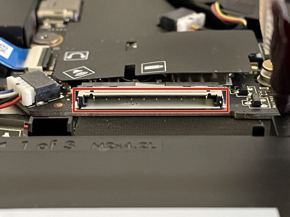
Be extremely careful when sliding the Battery connector out, as it is very easy to accidentaly bend the pins. Make sure to slide straight down, and avoid letting the connector twist or bend.
-
Gently disconnect the Battery by gripping the connector edges with both fingers and slide the connector straight down from the socket.
-
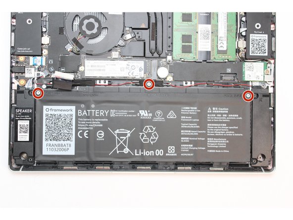
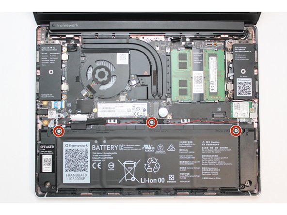
Unscrew the battery.
-
Using the T5 bit in the Framework Screwdriver, unscrew the three fasteners on the battery.
-
Remove the Battery from the Mainboard.
-
Use your fingertips to gently lift the battery up and away from the Bottom Cover. Carefully lift it out and keep it in a safe place.
-
Warning: Handle the battery by the plastic frame, make sure not to bend, scratch, cut, or puncture it, and keep it away from heat sources
-
-
-
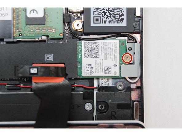
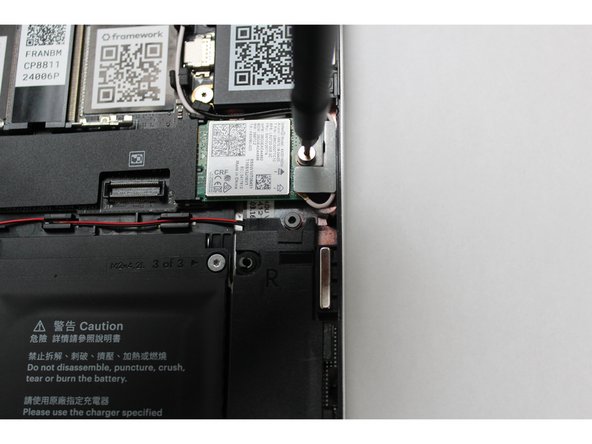
Unscrew the fastener using the T5 bit in the Framework screwdriver.
-
Remove the fastener and gently lift off the WiFi Bracket.
-
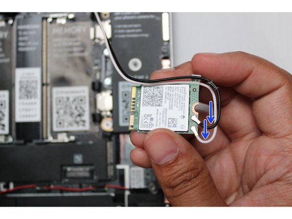
Gently remove the WiFi Module and place it to the side carefully, keeping the antenna cables connected if you're able to in order to save time and effort later.
-
-
-
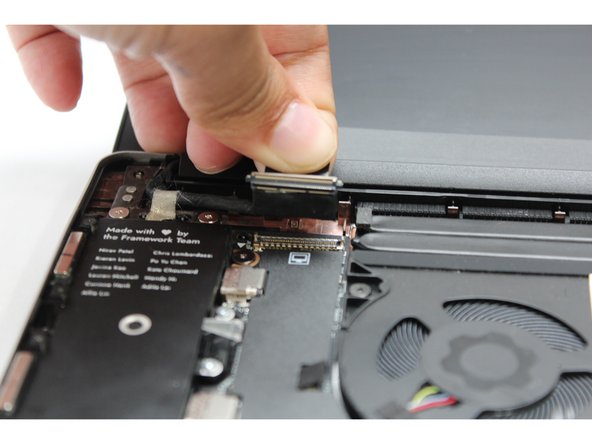
Find the black Display Cable that connects the display to the mainboard. Unplug the cable by pulling it directly upwards using the black pull tab.
-
Carefully lift up the silver grounding tape that is holding the Display Cable to the hinge.
-
Free the Display Cable from the Bottom Cover and carefully remove it from any routing pegs. It will remain connected to the display.
-
-
-
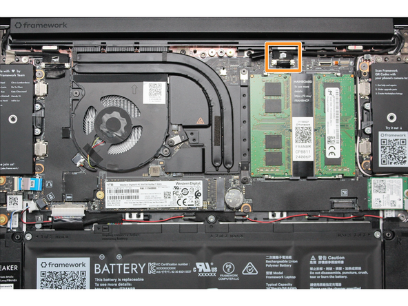
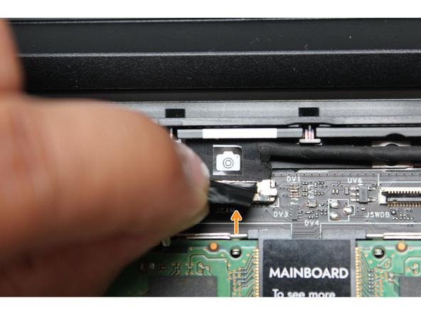
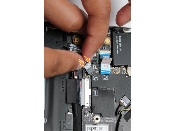
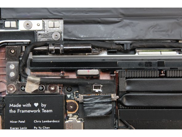
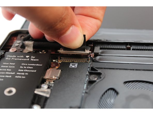
Using your fingers, carefully disconnect the Webcam cable on the top, right hand side by using the black pull tab to pull it directly upward.
-
-
-
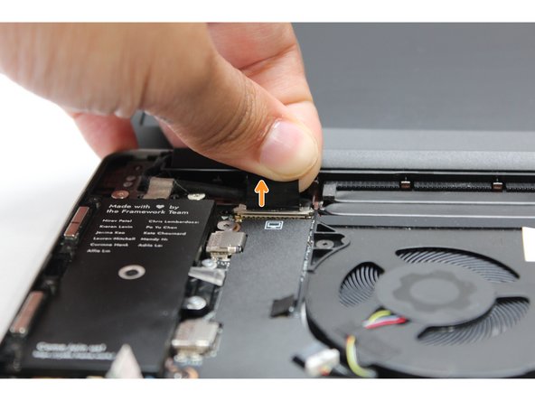
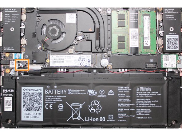
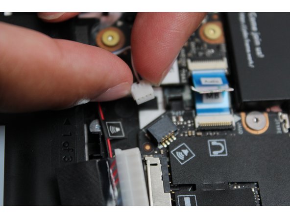
Using both fingers and a slight amount of force, disconnect the Speaker cable from the Mainboard by pulling it straight out.
-
-
-
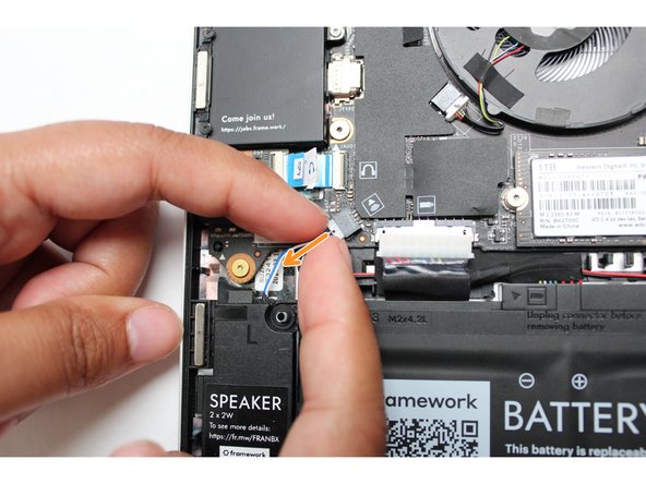
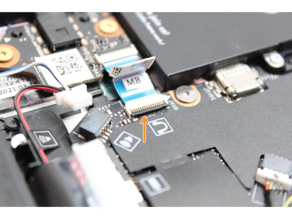
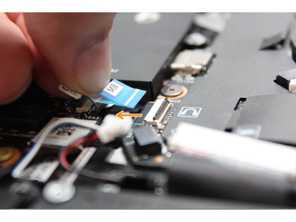
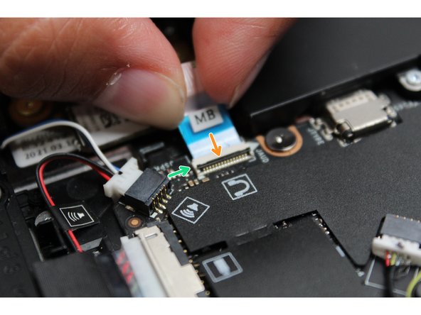
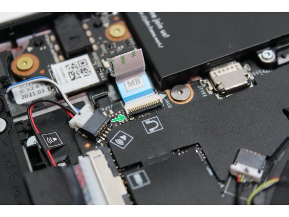
Disconnect the Audio Flex Cable from the Mainboard. Using your fingernail or the spudger end of the Framework Screwdriver flip up the black latch on the connector and then gently slide the cable out of the connector.
-
There should be no resistance when disconnecting this cable.
-
-
-
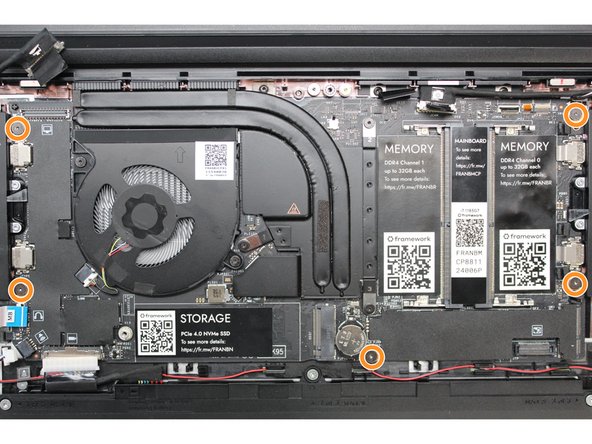
Remove the Mainboard fasteners
-
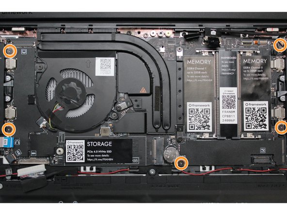
Using the T5 bit in the Framework Screwdriver, unscrew the five fasteners holding down the Mainboard.
-
These fasteners will completely come out unlike the five fasteners earlier. Be sure to keep them in a safe place during the replacement so that you do not lose them!
-
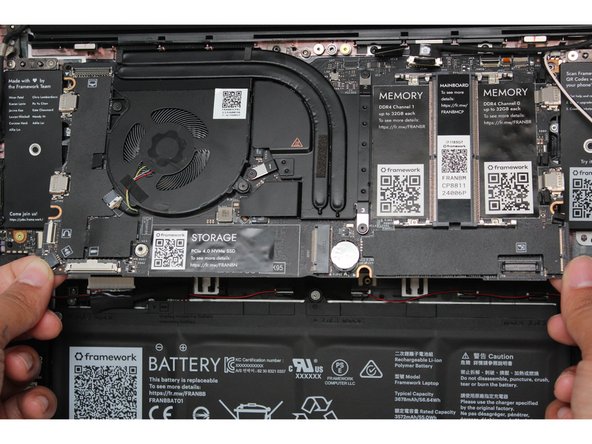
In order to lift the Mainboard off the Bottom Cover, grab it from the bottom edges and lift up very gently. There should be no resistance when lifting up the Mainboard unless a previous step was missed.
-
The components on the Mainboard are highly sensitive. Be sure to handle the board by the edges, and avoid touching any components on the board.
-
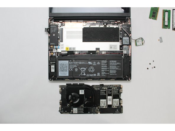
The Mainboard is now fully disconnected from the Framework Laptop.
-
-
-
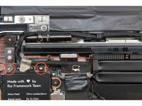
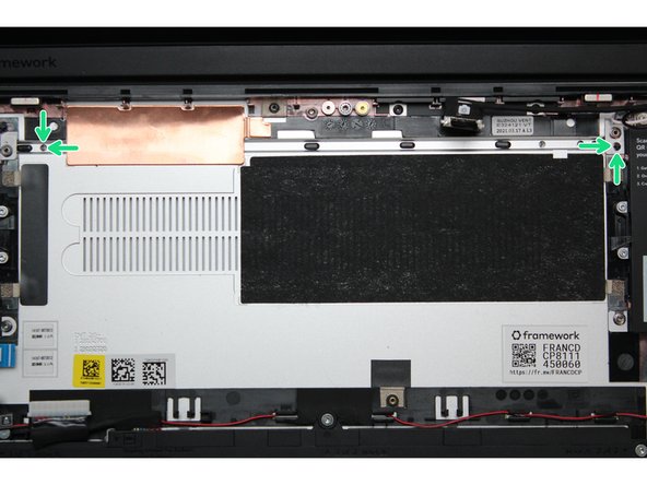
Using the T5 bit in the Framework screwdriver, the two fasteners on the left and right Hinges connecting to the Bottom Cover will need to be un-fastened.
-
-
-
Now that everything has been uninstalled, the Bottom Cover should now completely detach from the top cover.
-
Using the T5 bit in the Framework Screwdriver, the two fasteners on the left and right Hinges will need to be fastened onto the new Bottom Cover.
-
Now that your Bottom Cover is attached, let's get into reinstalling the rest of the parts.
-
-
-
The easiest way to properly install the Mainboard is by aligning the two alignment pins on the Bottom Cover with the two holes on the Mainboard.
-
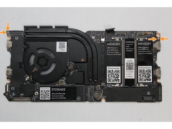
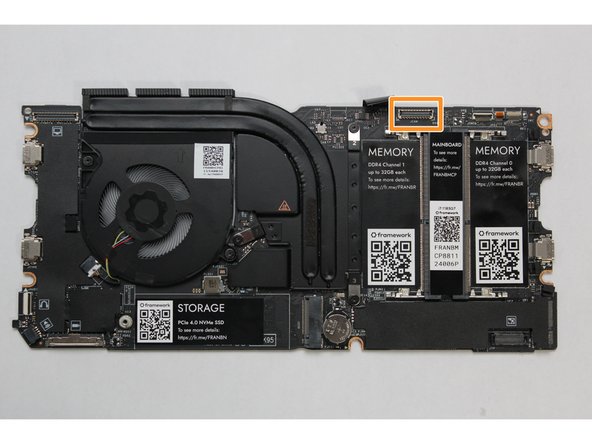
Take a close look at the actual Mainboard and you'll notice two small holes. You will see one hole on the top right and the other on the top left-hand side of the Mainboard as indicated in the first image with the orange arrows.
-
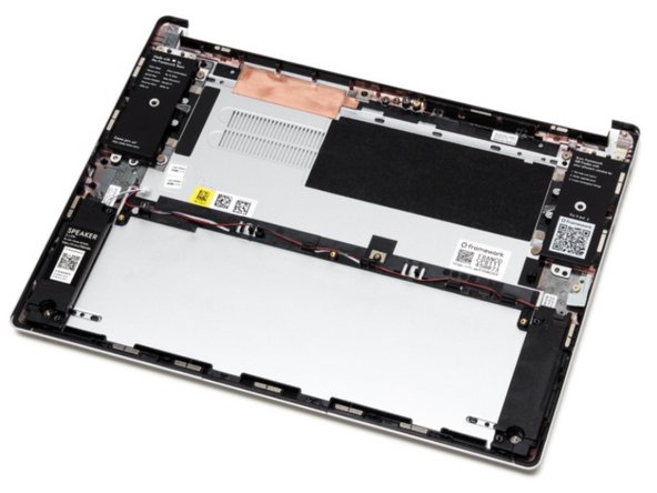
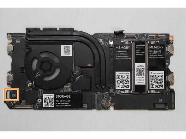
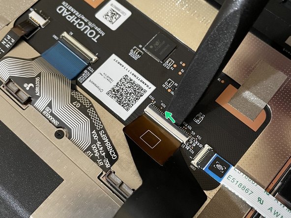
The alignment pins are located on the Bottom Cover as indicated with the green arrows in the second image.
-
Place the Mainboard on the Bottom Cover by using the alignment pins as a guide. Place the holes in the Mainboard directly over pins in the Bottom Cover. Both the left and right-hand side pins should fit into the holes perfectly.
-
The components located underneath the Mainboard are highly sensitive. Be sure to handle the board by the edges, and avoid touching any components on the board.
-
Once you have placed the Mainboard down be sure to make sure that the Speaker cable, Display cable, Camera cable, WiFi antenna cables, Audio Board cable, or the Battery cable are not stuck between the Mainboard and Bottom Cover as all the cables will need to be reconnected into their respective sockets after the Mainboard is secured in place.
-
Using the T5 bit in the Framework Screwdriver, screw the five fasteners into the Mainboard once it is properly seated.
-
-
-
Hold the pull tab on the Webcam Cable and connect it into the Mainboard by aligning the pins from the cable with the socket pins on the Mainboard.
-
-
-
Using two fingers, slide the Speaker cable into the Mainboard using a straight motion and a slight amount of force.
-
-
-
Connect the Audio Board cable by gently sliding it into the Mainboard. Make sure the black latch on the connector is flipped up so that you can slide the Audio Board Cable into the connector. Slide the cable straight in until the white line is almost at the edge of the connector
-
Using your finger or the spudger end of the Framework Screwdriver, flip the black latch down towards the Mainboard to lock the cable in place.
-
Once the black latch is secure the Audio Board cable should not come loose.
-
-
-
Hold the pull tab on the Display cable and connect it into the Mainboard by aligning the pins from the cable with the socket pins on the Mainboard.
-
-
-
While handling the Framework battery with the plastic frame, slide it into the Bottom Cover. Use the first image as a reference.
-
Before plugging the Battery connector back in, double check the pins on the Battery receptacle on the Mainboard, and make sure none of them look bent.
-
Don't plug the Battery connector in if pins look bent, as that will bend them even further. Reach out to Framework Support for guidance.
-
If you feel resistance when plugging in the Battery connector, stop, slide the connector back out, and make sure that no pins are being bent.
-
Carefully slide the Battery connector back into the mainboard, gripping both edges of the connector and sliding in straight without letting the connector twist or bend.
-
Using the T5 bit in the Framework Screwdriver, screw the three fasteners into place.
-
-
-
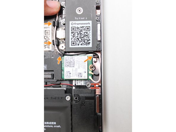
While keeping a finger on top of the antennas to hold them in place, insert the WiFi module into the socket on the Mainboard.
-
Once the module is properly inserted into the Mainboard, carefully route both the black and white WiFi Antenna cables into the black rubber routers as indicated in the first image. Place both the cables behind the metal structure located near the top right of the WiFi module as well.
-
The antenna cables should not touch the Speaker located below. Use the spudger end of the Framework Screwdriver to carefully push the white cable away from the Speaker if it is touching it.
-
Place the WiFi Bracket over the WiFi module and place the fastener in the hole. Using the T5 bit in the Framework Screwdriver, screw the fastener into place.
-
Connect the black and white WiFi Antennas to their respective sockets on the module if your antennas are disconnected. You can see a little triangular indicator on the module's label pointing out which color goes where. Make sure to align them well before applying force to click them into place, as the connectors are small and fragile.
-
-
-
Gently place the Input Cover keyboard side down on the Bottom Cover as indicated on the image. The cover should be about an inch and a half away from the bottom of the Mainboard so that you can comfortably install the Touchpad Cable.
-
Note: The orientation of the Input Cover matters. Study the first image in this step to ensure you are properly attaching the cover.
-
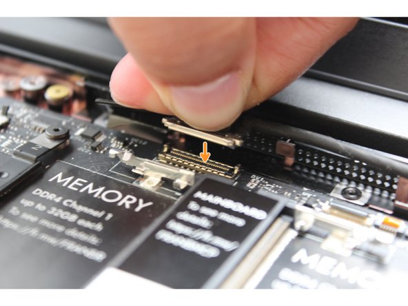
Locate the loop on the end of the Touchpad Cable and insert your finger into it.
-
Using slight force, connect the Touchpad Cable by aligning it to the socket on Mainboard. You should hear it click into place once properly connected.
-
-
-
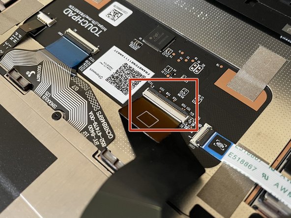
Before closing up the laptop, make sure that the Touchpad end of the Touchpad Cable is fully seated in the receptacle.
-
The cable should be inserted far enough that the white line almost touches the receptacle.
-
If it is not inserted far enough, you'll need to flip up the black latch on the other side of the connector, slide the cable in further, and then close the black latch again.
-
-
-
Once the Touchpad Cable is secured to the Mainboard, flip the Input Cover over the Bottom Cover so that the keyboard is facing up and attach it to the Bottom Cover by aligning the top and bottom edges of both covers.
-
Tip: The covers are magnetic and should fit into one another easily. If you feel any resistance simply lift the Input Cover up and try again.
-
-
-
Close the Framework Laptop and turn it upside down to reveal the empty Expansion Card bays and fasteners on the Bottom Cover.
-
Using the T5 bit in the Framework Screwdriver, screw all 5 fasteners back into the Bottom Cover.
-
Be sure to not over-tighten the fasteners.
-


- To purchase a Framework Laptop visit the Framework website
- Want to learn more about the Framework Laptop? Take a look at our blog
- If you have any questions or concerns, feel free to reach out to Framework Support
- To purchase a Framework Laptop visit the Framework website
- Want to learn more about the Framework Laptop? Take a look at our blog
- If you have any questions or concerns, feel free to reach out to Framework Support
Cancel: I did not complete this guide.
7 other people completed this guide.
5 Comments
- step 5: disconnecting the mainboard to touchpad cable is not optional as otherwise you cannot access the battery properly
- step 13: before unscrewing the hinges, bring the monitor in a 90° angle as otherwise the hinges cannot be lifted and detached from the bottom case properly
- before step 16: missing step of attaching the hinges to the bottom cover again.
- step 25: add notice that in the bottom right (or is it bottom left?) corner the case does not close fully (mentioned in the initial setup tutorial, but not in this one; I forgot already and it had me confused shortly)
Matthias Ley - Open Reply
In step 13 when we are told to unscrew the hinge the Bezel is also removed with no stated step. It is not that big and a logical next step but I fear some might miss.
Isaiah Polanco - Open Reply
Like Steve had said, there is no step for removing the webcam cable. I also noticed there was no step explaining how to route the antenna wires like in the antenna replacement guide. The only other thing I would like to add, is that I had a little bit of trouble removing the bottom assembly; specifically the hinges didn't want to come out cleanly. I would like to see a few tips on how to get the hinges in and out of place. Other than that, I the guide was great. Happy to say my replacement went smoothly.
Hunter White - Resolved on Release Reply
Step 14 connects the webcam to the mainboard, but there's no corresponding earlier disconnect step. If revising, maybe also make assembly steps in the reverse order to the disassembly steps (unless there's good reason not to). This would be more logical and is usual practice when writing such guides.
Steve Burgess - Resolved on Release Reply