
Introduction
This is one of the more challenging repairs on the Framework Laptop, but in the event you have antenna cables or connectors that are damaged, you can resolve this by replacing the Antenna Module.
Tools
Parts
No parts specified.
-
-
Power off the Framework Laptop by navigating to the Windows icon on the bottom left and clicking on "Power" followed by "Shut down," or if on Linux, the equivalent action there.
-
-
-
Unplug your power cable from the USB-C Expansion Card in your Framework Laptop.
-
-
-
Close the lid on your Framework Laptop and place it upside down on a soft, non-marring surface, such as the bag that it shipped in.
-
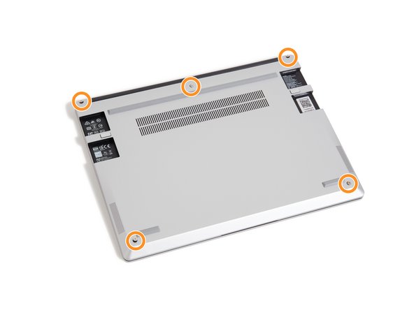
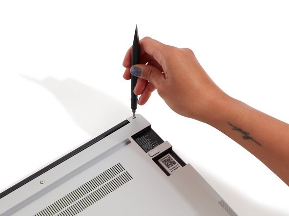
Using the T5 bit in the Framework Screwdriver, unscrew the 5 fasteners on the Bottom Cover. These fasteners will remain attached in the Bottom Cover so that you do not lose them.
-
The fastener on the bottom left (circled in red) will not unscrew as far as the others, as it is acting as a lifter for the Input Cover.
-
You'll hear this fastener start clicking as you rotate when it is unscrewed far enough.
-
Do not use a powered tool for these steps, as this will likely result in damage to the fasteners.
-
-
-
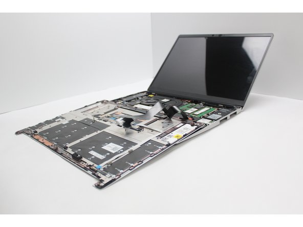
Flip the Framework Laptop back over and open the lid to around 120 degrees.
-
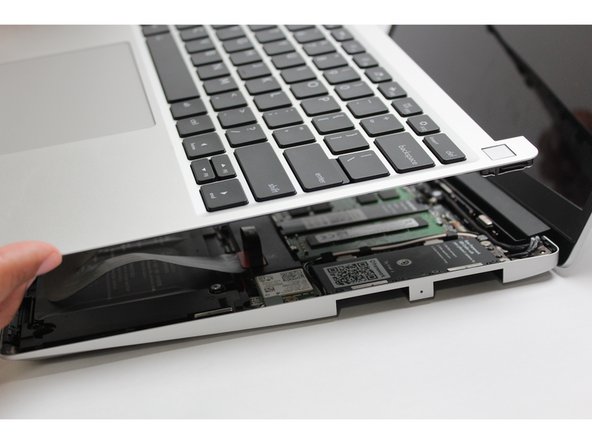
Important: Pull the Input Cover off carefully as it is still attached to the Mainboard via the Touchpad Cable. You don't need to disconnect this cable to do most repairs. You can just flip the Input Cover over. If you do want to disconnect it though, make sure to disconnect the Mainboard side using the finger loop over the orange label.
-
The bottom right corner of the Input Cover lifts up when the five fasteners are properly unscrewed from the previous step. You should not have to use any excessive force to remove the Input Cover.
-
Carefully lift the cover up from the bottom right corner. If you need to, you can use the spudger end of the Framework Screwdriver to lift it as well. Lift the Input Cover off the Mainboard, flip it over (keyboard side down), and place it about halfway on the Bottom Cover.
-
Be sure not to put too much force on the Touchpad Cable when doing this.
-
If the LEDs on the left and right sides of the system are flashing red when you lift off the cover, it means the system is still powered on. Make sure your power cable isn't plugged in and that you have shut down correctly.
-
Note that it may take up to 30 seconds after shutting down for the system to fully power off. Wait until the LEDs stop flashing before proceeding.
-
You should keep the Battery connector plugged in unless you need to replace the Battery, Mainboard, or Speakers. This connector is easy to accidentally damage, so it's better to not handle it.
-
-
-
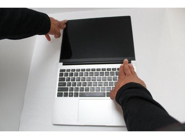
Open the Framework Laptop 180 degrees to remove the Bezel.
-
Be careful to check that the back left and right fasteners that you unscrewed earlier don't get caught on the lid as you open it to 180 degrees.
-
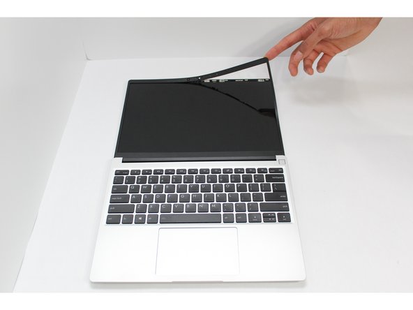
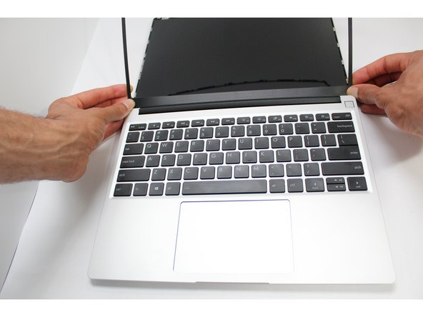
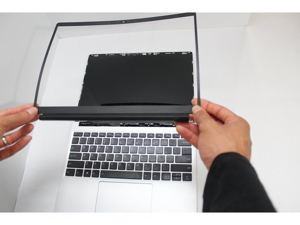
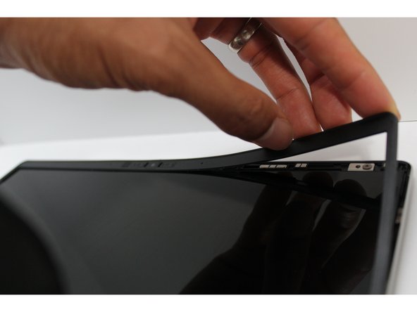
The Framework Bezel is attached by magnets so you will not require any tools to remove it. Just use your fingernail and pry the Bezel away from the display from one of the top corners of the Framework Laptop.
-
Once the Bezel starts peeling off towards the bottom of the Display, lift it up using caution. You might feel a little resistance due to the adhesive at the bottom of the display.
-
-
-
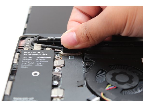
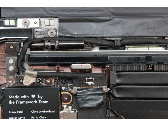
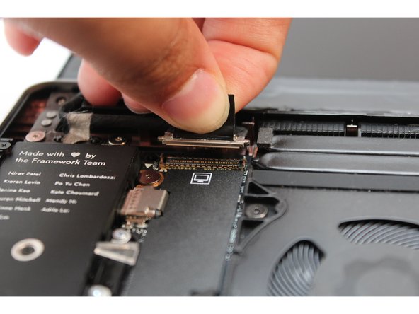
Find the black Display Cable that connects the display to the mainboard. Unplug the cable by pulling it directly upwards using the black pull tab.
-
Carefully lift up the silver grounding tape that is holding the Display Cable to the hinge.
-
Free the Display Cable from the Bottom Cover and carefully remove it from any routing pegs. It will remain connected to the display.
-
-
-
Using the T5 bit in the Framework Screwdriver, unscrew the 4 fasteners connecting the Display to the Top Cover.
-
The Display is now fully unattached to the Top Cover, you can gently lift it up from the corner using your fingernail.
-
Be sure to only handle the Display by the side edges and avoid touching the bottom area.
-
-
-
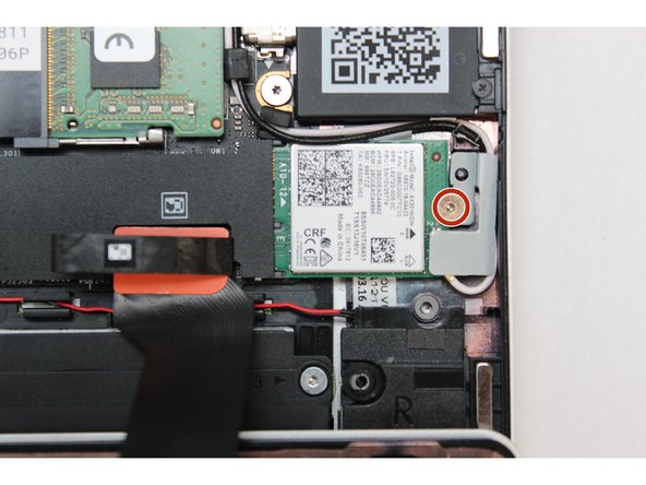
Using the T5 bit in the Framework Screwdriver, unscrew the fastener on the WiFi module.
-
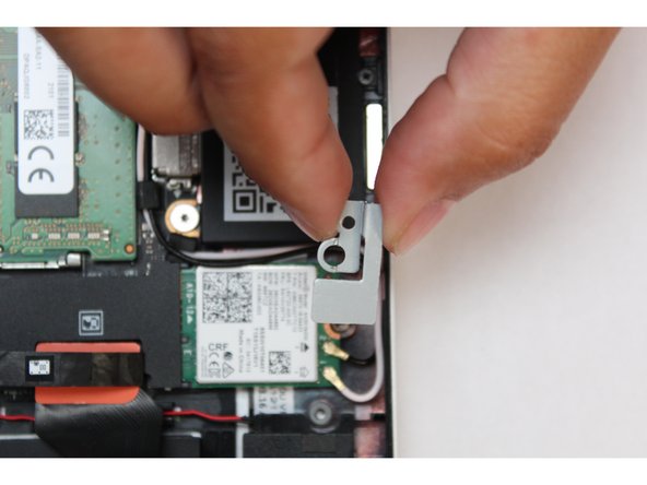
Remove the fastener and gently lift off the WiFi Bracket.
-
-
-
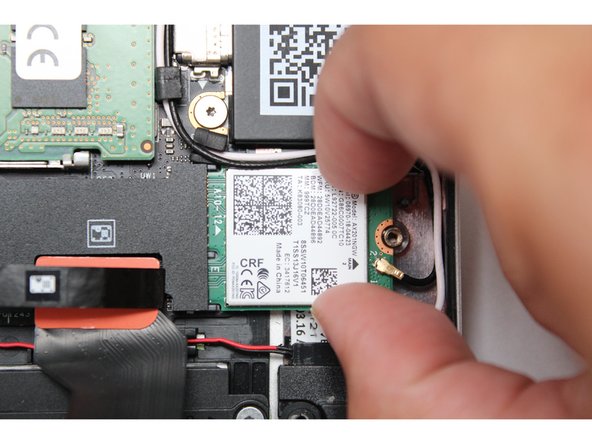
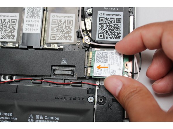
Using your fingers gently slide the WiFi module out of the socket.
-
Disconnect the black and white antenna cables by carefully pulling them upwards away from the card, being cautious to not bend the connector.
-
-
-
Carefully pull the antenna cables out of the rubber and plastic channels that they are routed through it the system.
-
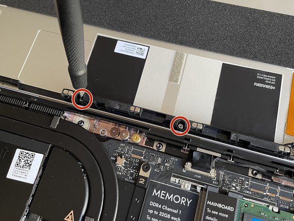
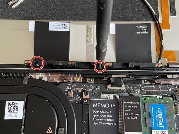
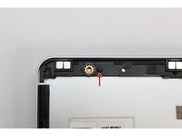
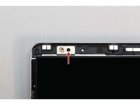
Using the T5 bit in the Framework Screwdriver, remove the two fasteners that are holding the Antenna Module into the Top Cover.
-
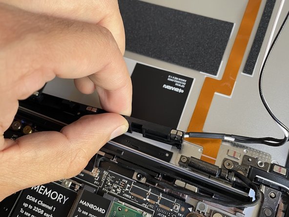
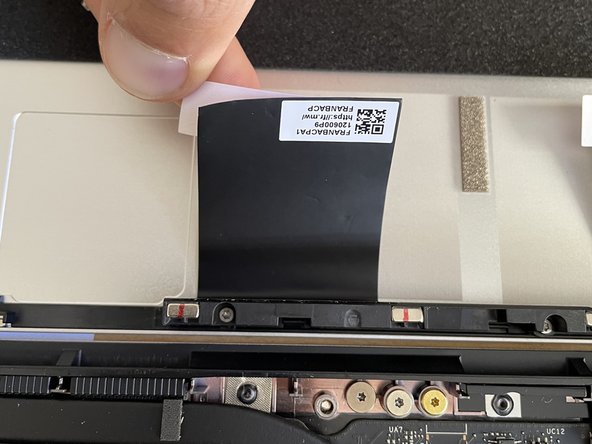
Pull the Antenna Module up and away, peeling the black grounding stickers off of the Top Cover with them. Note that the adhesive may be strong, and it is ok if a little residue is left on the Top Cover afterwards.
-
-
-
Fasten the new Antenna Module into the Top Cover using the two fasteners you removed before, using the T5 bit in the Framework Screwdriver.
-
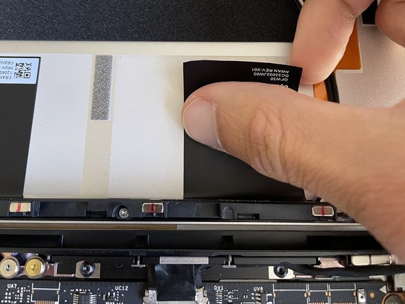
Peel away the white backing liner on one of the black grounding pads and stick the pad onto the Top Cover.
-
Repeat on the second grounding pad.
-
-
-
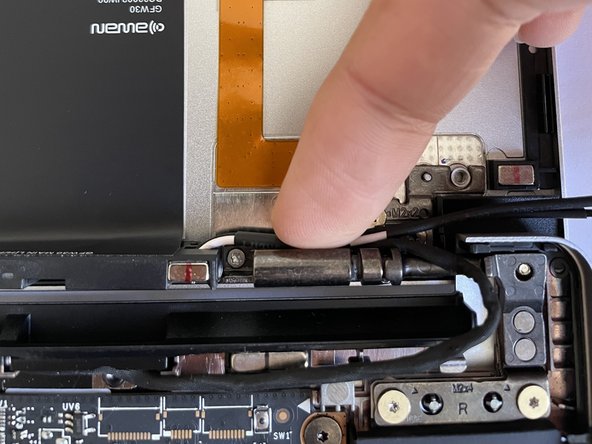
Peel away the blue backing liner on the antenna cable and stick the cable onto the hinge.
-
Route the antenna cables through the hinge area, with the white and black cables sitting flat against the bottom of the Bottom Cover as much as possible. Avoid letting the cables twist or overlap, as this will interfere with the Input Cover and power button. You can use the spudger end of the Framework Screwdriver to help push the cables.
-
Route the antenna cables through each of the channels and rubber brackets.
-
-
-
There are four alignment pins located on the Top Cover. They are located right next to the four fastener slots. Place the silver brackets connected to Display directly over the pins.
-
Be sure to only handle the Display by the side edges and avoid touching the bottom area.
-
-
-
Using the T5 bit in the Framework Screwdriver screw the four fasteners into place.
-
Be sure to not over tighten the fasteners.
-
-
-
Route the black Display Cable through the routing channel as indicated in the picture.
-
Secure the silver grounding tape as indicated in the first image.
-
Using the black pull tab, align the Display Cable connector with the connection on the Mainboard and firmly press down.
-
The Display installation is now complete.
-
-
-
Open the Framework Laptop 180 degrees to attach the Bezel. Make sure the fasteners in the top left and right corners of the Bottom Cover aren't interfering with the opening.
-
Align the corners of the Bezel to the display and place it down. The Bezel is attached by magnets and should easily click into place.
-
Make sure that all of the corners and edges of the Bezel are fully connected to the Top Cover. If the corners are not aligned. carefully lift up the part of the bezel and guide it into place.
-
-
-
Remove the plastic covers from the antenna cables, and carefully connect the black and white WiFi antenna cables into their respective sockets on the module. Make sure to align them well before applying force to click them into place, as the connectors are small and fragile.
-
If you need a video overview on this, check this out.
-
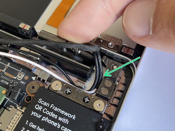
Once both the black and white WiFi Antenna cables are connected to the module, make sure they are rotated downwards as indicated in the second picture with the blue arrows.
-
While keeping a finger on top of the antennas to hold them in place, insert the WiFi module into the socket on the Mainboard.
-
-
-
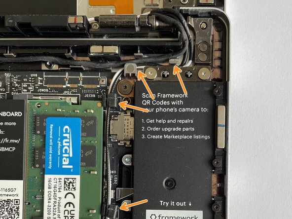
Once the module is properly inserted into the Mainboard, carefully route both the black and white WiFi Antenna cables into the black rubber routers as indicated in the first image. Place both the cables behind the metal structure located near the top right of the WiFi module as well.
-
The antenna cables should not touch the Speaker located below. Use the spudger end of the Framework Screwdriver to carefully push the white cable away from the Speaker if it is touching it.
-
Place the WiFi Bracket over the WiFi module and place the fastener in the hole. Using the T5 bit in the Framework Screwdriver, screw the fastener into place.
-
Be sure to not over-tighten the fastener.
-
-
-
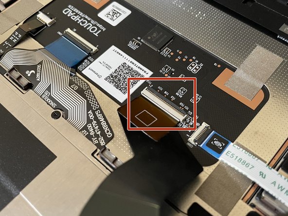
Before closing up the laptop, make sure that the Touchpad end of the Touchpad Cable is fully seated in the receptacle.
-
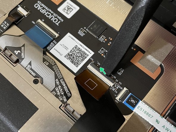
The cable should be inserted far enough that the white line almost touches the receptacle.
-
If it is not inserted far enough, you'll need to flip up the black latch on the other side of the connector, slide the cable in further, and then close the black latch again.
-
-
-
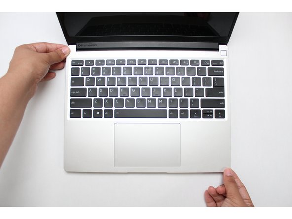
Flip the Input Cover over the Bottom Cover so that the keyboard is facing up and attach it to the Bottom Cover by aligning the top and bottom edges of both covers.
-
Tip: The covers are magnetic and should fit into one another easily. If you feel any resistance simply lift the Input Cover up and try again.
-
-
-
Close the Framework Laptop and turn it upside down to reveal the five fasteners on the Bottom Cover.
-
Using the T5 bit in the Framework Screwdriver, screw all 5 fasteners back into the Bottom Cover.
-
Be sure to not over-tighten the fasteners.
-


- To purchase a Framework Laptop visit the Framework website
- Want to learn more about the Framework Laptop? Take a look at our blog
- If you have any questions or concerns, feel free to reach out to Framework Support
- To purchase a Framework Laptop visit the Framework website
- Want to learn more about the Framework Laptop? Take a look at our blog
- If you have any questions or concerns, feel free to reach out to Framework Support
Cancel: I did not complete this guide.
9 other people completed this guide.
One Comment
Will the Wi-Fi antenna retention bracket be available for purchase?
Won Aksomboon - Resolved on Release Reply