
Introduction
Before you get started, if you are running Windows, there are a few steps you'll need to take:
- If you’re upgrading from an 11th Gen Intel Core to 13th Gen Intel Core system, we recommend upgrading to Windows 11 before swapping the Mainboard.
- Make sure you back up your data.
- If you’re running a Pro version of Windows, suspend BitLocker by following our directions here.
- If you're running a Home version of Windows and have enabled Windows Device Encryption, you will want to disable it. To disable it, press Win + I to open Settings and select Privacy & Security. Then, click on Device Encryption on the right panel and toggle the setting to Off.
- Find your product key or link your Windows license to a Microsoft account to make sure you can re-activate Windows after the change.
This guide combines all of the possible upgrades introduced with 13th Gen Intel Core so if you are skipping one or more of the upgrades please see which steps to skip below (if you are simply carrying out one of these upgrades we recommend the dedicated guide for that component).
- The guide assumes you are upgrading your Mainboard but if you are not, you can skip step 9, steps 12-18, step 44, and steps 46-49.
- If you are not upgrading your Speakers you can skip steps 21-28.
- If you are not upgrading your Battery but are upgrading the Speakers there are not steps to skip. (as you will still need to remove the battery to upgrade Speakers).
- If you are not upgrading both Battery and Speakers you can skip steps 19-32
- If you are not upgrading your Hinges you can skip steps 35-38.
- If you are not upgrading your Display but are upgrading Hinges, there are no steps to skip (as you will need to remove the Display in order to upgrade Hinges)
- If you are not upgrading both Display and Hinges you can skip steps 33-40 and step 42.
-
-
Power off the Framework Laptop by navigating to the Windows icon on the bottom left and clicking on "Power" followed by "Shut down," or if on Linux, the equivalent action there.
-
-
-
Unplug your power cable from the USB-C Expansion Card in your Framework Laptop.
(I had formerly left a long comment here about how you guys 'forgot' to have a bit about removing the expansion cards...and while some official guide on this is probably a good idea to have, it's...not actually necessary to remove them! Even though in the build guide, they go in last, they don't actually need to come out in order to replace the screen! Heh.)
-
-
-
Close your laptop completely and turn it over so you can access the Expansion Cards.
-
While keeping the release button pressed, use your other fingers to slide the Expansion Card away from the laptop.
-
Important: You may have to use a little bit of force to fully disconnect the Expansion Card.
-
Make sure each Expansion Card is fully removed before proceeding to the next step.
-
-
-
Close the lid on your Framework Laptop and place it upside down on a soft, non-marring surface, such as the bag that it shipped in.
-
Using the T5 bit in the Framework Screwdriver, unscrew the 5 fasteners on the Bottom Cover. These fasteners will remain attached in the Bottom Cover so that you do not lose them.
-
The fastener on the bottom left (circled in red) will not unscrew as far as the others, as it is acting as a lifter for the Input Cover.
-
You'll hear this fastener start clicking as you rotate when it is unscrewed far enough.
-
Do not use a powered tool for these steps, as this will likely result in damage to the fasteners.
It would be super nice if the lower-left screw were circled in red as the text indicates!
Mike Shaver - Resolved on Release Reply
Thank you for writing the specific detail on the lower left corner screw.
I thought something was not working correct until re-read this guide.
Patrick Corey - Resolved on Release Reply
-
-
-
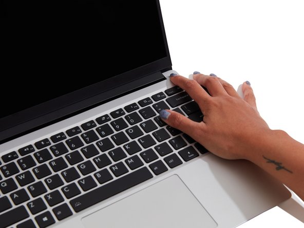
Flip the Framework Laptop back over and open the lid to around 120 degrees.
-
Important: Pull the Input Cover off carefully as it is still attached to the Mainboard via the Touchpad Cable. You don't need to disconnect this cable to do most repairs. You can just flip the Input Cover over. If you do want to disconnect it though, make sure to disconnect the Mainboard side using the finger loop over the orange label.
-
The bottom right corner of the Input Cover lifts up when the five fasteners are properly unscrewed from the previous step. You should not have to use any excessive force to remove the Input Cover.
-
Carefully lift the cover up from the bottom right corner. If you need to, you can use the spudger end of the Framework Screwdriver to lift it as well. Lift the Input Cover off the Mainboard, flip it over (keyboard side down), and place it about halfway on the Bottom Cover.
-
Be sure not to put too much force on the Touchpad Cable when doing this.
-
If the LEDs on the left and right sides of the system are flashing red when you lift off the cover, it means the system is still powered on. Make sure your power cable isn't plugged in and that you have shut down correctly.
-
Note that it may take up to 30 seconds after shutting down for the system to fully power off. Wait until the LEDs stop flashing before proceeding.
-
You should keep the Battery connector plugged in unless you need to replace the Battery, Mainboard, or Speakers. This connector is easy to accidentally damage, so it's better to not handle it.
Important: Pull the Input Cover off carefully as it is still attached to the Mainboard via the Touchpad Cable. You don't need to disconnect this cable to do most repairs. You can just flip the Input Cover over. If you do want to disconnect it though, make sure to disconnect the Mainboard side using the finger loop over the orange label.
While that’s true for most repairs, it’s pretty much essential to disconnect that cable for this repair, so I think the guide should probably amend this boilerplate!
Mike Shaver - Resolved on Release Reply
You should flip the keyboard around the x-axis (so that the back edge comes towards you as you flip) and not the z-axis (resulting in the left edge rotating to the right). I started to do the z-axis and the touchpad cable was getting twisted. I am capable of messing up all instructions. This is my anti-super-power... or joker power in the Wild Cards universe.
-
-
-
Disconnect the Touchpad Cable from the Mainboard by inserting your finger into the loop and pull directly upward using a slight amount of force.
-
Avoid disconnecting the Touchpad side of the cable unless you need to replace the Touchpad Cable itself, since that connector is more fragile.
-
Once the Touchpad Cable is disconnected, remove the Input Cover away from the Mainboard.
-
The Input Cover is now fully disconnected from the Bottom Cover and can be set aside.
-
-
-
Be extremely careful when sliding the Battery connector out, as it is very easy to accidently bend the pins. Make sure to slide straight down, and avoid letting the connector twist or bend.
-
Gently disconnect the Battery by gripping the connector edges with both fingers and slide the connector straight down from the socket.
-
-
-
Using both fingers and a slight amount of force, disconnect the Speaker cable from the Mainboard by pulling it straight out.
-
-
-
Disconnect the Audio Flex Cable from the Mainboard. Using your fingernail or the spudger end of the Framework Screwdriver flip up the black latch on the connector and then gently slide the cable out of the connector.
-
There should be no resistance when disconnecting this cable.
-
-
-
Using your fingers, carefully disconnect the Display cable on the top, left hand side by using the pull tab to pull it upward.
-
-
-
Using your fingers, carefully disconnect the Webcam cable on the top, right hand side by using the black pull tab to pull it directly upward.
-
-
-
Using the spudger end of the Framework Screwdriver, release the black and white WiFi Antenna cables by gently lifting them out from the rubber holders.
-
Unscrew the fastener in the silver bracket holding down the WiFi module.
-
Remove the WiFi bracket and gently pull the WiFi module out of the socket as indicated in the image.
-
You do not need to disconnect the black and white WiFi Antenna cables from the WiFi module. Keeping them connected will make it easier to insert the card back into place.
-
-
-
Using both fingers, gently pull the top and bottom metal release clips away from the Memory just enough for the module to pop up.
-
The top and bottom clips should be released simultaneously for a single Memory module.
-
The Memory module will pop up at a 20 degree angle. Carefully slide it out of the socket and remove it from the Mainboard.
-
If you have more than one Memory module in place, repeat the steps for the other module.
-
-
-
Unscrew the fastener holding down the Storage.
-
The Storage module will pop up at a 20 degree angle.
-
Slide the module out of the socket using a straight motion and remove it from the Mainboard.
-
-
-
Using the T5 bit in the Framework Screwdriver, unscrew the five fasteners holding down the Mainboard.
-
These fasteners will completely come out. Be sure to keep them in a safe place during the replacement so that you do not lose them!
-
-
-
In order to lift the Mainboard off the Bottom Cover, grab it from the bottom edges and lift up very gently. There should be no resistance when lifting up the Mainboard unless a previous step was missed.
-
The components located underneath the Mainboard are highly sensitive. Be sure to handle the board by the edges, and avoid touching any components on the board.
-
The Mainboard is now fully disconnected from the Framework Laptop.
-
-
-
The easiest way to properly install the Mainboard is by aligning the two alignment pins on the Bottom Cover with the two holes on the Mainboard.
-
Take a close look at the actual Mainboard and you'll notice two small holes. You will see one hole on the top right and the other on the top left-hand side of the Mainboard as indicated in the first image with the orange arrows.
-
The alignment pins are located on the Bottom Cover as indicated with the green arrows in the second image.
-
Place the Mainboard on the Bottom Cover by using the alignment pins as a guide. Place the holes in the Mainboard directly over pins in the Bottom Cover. Both the left and right-hand side pins should fit into the holes perfectly.
-
The components located underneath the Mainboard are highly sensitive. Be sure to handle the board by the edges, and avoid touching any components on the board.
-
Once you have placed the Mainboard down be sure to make sure that the Speaker cable, Display cable, Camera cable, WiFi antenna cables, Audio Board cable, or the Battery cable are not stuck between the Mainboard and Bottom Cover as all the cables will need to be reconnected into their respective sockets after the Mainboard is secured in place.
-
-
-
Using the T5 bit in the Framework Screwdriver, screw the five fasteners into the Mainboard once it is properly seated.
-
Be sure to not over-tighten the fasteners.
-
-
-
Using the T5 bit in the Framework Screwdriver, unscrew the three fasteners on the battery.
-
Note: The screws will come loose after a few revolutions however they will remain attached to the battery.
-
-
-
Use your finger tips to gently lift the battery up and away from the bottom cover. Carefully lift it out and keep it in a safe place.
-
Warning: Handle the battery by the plastic frame, make sure not to bend, scratch, cut, or puncture it, and keep it away from heat sources
-
-
-
Locate one of two pieces of black tape and carefully peel it back to reveal the black and red speaker wires.
-
Do not completely remove the tape from the Bottom Cover, peel it back just enough to reveal the wires.
-
Carefully lift the wires out of the wire routers and very gently pull the wires down so that they are free.
-
-
-
The speakers are now disconnected. You can lift both the left and right speaker out of the Bottom Cover.
-
-
-
Place both the Left and Right speakers in their respective spaces on the Bottom Cover by aligning the pegs with the rubber gaskets.
-
Note: You'll notice an L and R on both speakers to help you figure out the proper placement.
-
-
-
Peel the black tape back and place the wires under it. Cover the wires with same tape.
-
Place the wires into the wire router next to the other piece of black tape. Peel the tape back and place the wires under it. Cover the wires with same tape.
-
Route the wires through each of the wire routers. You can use your fingernail to secure the wires in place.
-
Make sure the Speaker is not touching the white or black antenna from the WiFi Module.
-
-
-
While handling the Battery with the plastic frame, slide it into the Bottom Cover. Use the first image as a reference.
-
-
-
Before plugging the Battery connector back in, double check the pins on the Battery receptacle on the Mainboard, and make sure none of them look bent.
-
Don't plug the Battery connector in if pins look bent, as that will bend them even further. Reach out to Framework Support for guidance.
-
If you feel resistance when plugging in the Battery connector, stop, slide the connector back out, and make sure that no pins are being bent.
-
-
-
Carefully slide the Battery connector back into the Mainboard, gripping both edges of the connector and sliding in straight without letting the connector twist or bend.
-
-
-
Using the T5 bit in the Framework Screwdriver, screw the three fasteners into place.
-
The battery is now fully connected to the Framework Laptop.
-
-
-
Open the Framework Laptop 180 degrees to remove the Bezel.
-
The Framework Bezel is attached by magnets so you will not require any tools to remove it. Just use your fingernail and pry the Bezel away from the display from one of the top corners of the Framework Laptop.
-
Once the Bezel starts peeling off towards the bottom of the Display, lift it up using caution. You might feel a little resistance due to the adhesive at the bottom of the display.
The bottom of the screen is held together by something absolutely indestructible . I found there's a way you need to wiggle and lift, but this instruction is not included in this spec
Paul M Kovac - Open Reply
Same as above, in my case three of the four bezel adhesevies were so stuck that they eventually remained on the screen frame. Wiggling or softly using the spludger in order to lift the bottom of the Bezel are two ways of removing it, but mind not to scratch the screen!
Pascal Belin - Open Reply
Once the Bezel starts peeling off towards the bottom of the Display, lift it up using caution. You might feel a little resistance due to the adhesive at the bottom of the display.
This is NOT true in my last screen replacement process, the bezel adhesive stuck to the display firmly and I used quite amount of wiggling to successfully separate the bezel and the (supposed to be fragile) bottom part of the display. The original display thankfully didn't end up damaged because of it, however, please be careful.
林博仁(Buo-ren, Lin) - Resolved on Release Reply
-
-
-
Using the T5 bit in the Framework Screwdriver, unscrew the 4 fasteners connecting the Display to the Top Cover.
-
The Display is now fully unattached to the Top Cover, you can gently lift it up from the corner using your fingernail.
-
Be sure to only handle the Display by the side edges and avoid touching the bottom area.
-
-
-
Rotate the lid back up to a 90 degree angle to make it easier to remove and install the Hinges.
-
With the T5 bit in your Framework Screwdriver, unscrew the four fasteners that hold the Hinges into the Bottom Cover.
-
Note that these fasteners are longer than the ones used to attach the Display and Hinges into the Top Cover. Make sure to keep them separate from those.
-
With the Top Cover assembly now unfastened from the Bottom Cover assembly, lift it up and lay it flat, being careful to not pull on the cables too much.
-
-
-
Move the Antenna and Webcam cables out of the way carefully to make sure you have easy access to the fasteners on the right Hinge.
-
Unscrew the three fasteners on the right Hinge using the T5 bit in your Framework Screwdriver, and then remove the Hinge from the Top Cover.
-
Repeat this for the three fasteners on the left Hinge and remove the Hinge from the Top Cover.
-
-
-
Pre-rotate the new Hinges to a 90 degree angle to make them easier to install.
-
Place the left and right Hinges into the Top Cover and fasten them into place with the three fasteners each that you previously removed.
-
Carefully place the Top Cover assembly with the Hinges installed onto the Bottom Cover assembly and fasten the left and right Hinges into the Bottom Cover using two fasteners each that you previously removed.
-
-
-
Stick the antenna cables down onto the new Hinge.
-
Route the antenna cables through the hinge area, with the white and black cables sitting flat against the bottom of the Bottom Cover as much as possible. Avoid letting the cables twist or overlap, as this will interfere with the Input Cover and power button. You can use the spudger end of the Framework Screwdriver to help push the cables.
-
Route the antenna cables through each of the channels and rubber brackets.
-
-
-
There are four alignment pins located on the Top Cover. They are located right next to the four fastener slots. Place the silver brackets connected to Display directly over the pins.
-
Be sure to only handle the Display by the side edges and avoid touching the bottom area.
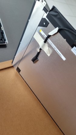
Same as Scott, the part I felt most worried in the process was when removing the tape that maintained the display cable stuck to the back of the new display kit. My main concern was no to bend the brand new display... Hopefuly you can use the spludger to lift a corner of the tape, and once it's done you can genlty peel it off.
Pascal Belin - Open Reply
Before installing the display, should mention to detach the display cable from where it is taped to the back of the new panel, being careful to not damage the permanent connector at the panel end.
Scott Rabinow - Resolved on Release Reply
My screen came with a protective layer on it. The screen removal tip/sticker is hard to spot. It's on the upper right corner and could wrapped so you need to peel it out carefully.
-
-
-
Using the T5 bit in the Framework Screwdriver screw the four fasteners into place.
-
Be sure to not over tighten the fasteners.
-
-
-
Route the black Display Cable through the routing channel as indicated in the picture.
-
Secure the silver grounding tape as indicated in the first image.
-
Using the black pull tab, align the Display Cable connector with the connection on the Mainboard and firmly press down.
-
The Display installation is now complete.
@Maxr1998 I believe the tape that was used to secure the cable on the backside of the panel wasn't used during assembly and should be peeled off and discarded.
林博仁(Buo-ren, Lin) - Resolved on Release Reply
The display panel peel must be removed before replacing the bezel.
Scott Rabinow - Resolved on Release Reply
-
-
-
If installing a new Bezel, remove the liner pieces on the bottom of the Bezel to expose the adhesive (if present).
Applying the bezel on the display can take multiple tries, especially if you encounter the problem(s) mentioned in the previous and the next section. Just in case you get worried about the glue drying or whatever, I placed and removed the bezel multiple times, as well as letting it sit for a good while with the adhesive covers removed, and nothing bad happened.
It seems almost all of the comments here belong in the next section about actually installing the bezel - only a few of them (if any?) are pertinent to removing the liner pieces to expose the adhesive on the bezel, which is the only action taken here. It's a bit bonkers there's 17 comments before mine in this section about removing liner pieces and only 4 comments at the time of writing in the next section about bezel installation, the latter of which is clearly an order of magnitude more difficult it seems.
Richard Lloyd - Resolved on Release Reply
My bezel seemed to install well but the lower left hand corner ended up becoming quite stuck and warped for some reason (perhaps how a particular cable was positioned near the microphone).
It jammed and was almost impossible to open. I have had to detach the lower hinge of the bezel for now and will need a replacement.
Not the best experience.
Also had issues with the left corner of the bezel. What happened was I was trying to route the left corner cable below the hinge! That was stupid of me, but it seemed like the appropriate place for the cable to go without much knowledge of laptop bezels. I did fully read and follow the guide, and had the right cable properly fitted; but for some reason it seemed the left cable was supposed to fit under the hinge.
For anyone who might run into the same problem like I did, here is a picture of how the left cable is supposed to be properly seated:
Also, to be fair, the cable was already a bit seated under the hinge when I first opened the laptop, which led me to assume that was how it was supposed to be.
Ciaran Sanders - Resolved on Release Reply
the guide says "the ezel" instead of "the bezel" at the end of the 4th bullet point.
Chickenman - Resolved on Release Reply
For me this was really simple and took about 30 seconds.
Richard Tango-Lowy - Resolved on Release Reply
installed the bezel carefully, or so i thought, when i was finished closed the lid (top cover still off) and the captive screws levered the screen which caused the hinge cover at the bottom of the bezel to just shear off - awesome...i had to re-separate the bezel completely and install from the hinge cover first and then tip the laptop so the captive screws didn't catch in order to check the function again, working now but i've also got half a hinge cover separated from the bezel. Kind of took the shine off my laptop i've been waiting 4 months for
Surprisingly, the bezel was by far the hardest item to install for me. I found that it's easier if done without the top cover, however, be very careful to keep the screws fully seated in when moving the hinge - they can lodge themselves in the wrong spot and cause damage otherwise. This was also pointed out in a comment below, but it should really be a warning at the top of each guide.
As many have noted, the difficult part is getting the lower corners to sit flush. After a lot of tries the best technique I found is:
- release tension from the cables by taking them out from some of their holding brackets
- route them so that, with the laptop sitting flat and horizontal, their highest point is no higher than the hinge's. The picture in the guide shows how to do that - the hinge edges are skinnier than the rest, and you're trying to wrap around that tiny bit of space that they leave.
Even then it's not perfect and my bottom right corner wants to sit a hair higher than the others.
Demetrio Girardi - Resolved on Release Reply
I also had an issue when placing the bottom left of the bezel onto the screen. A cable connecting to the display was causing the the bezel to just not sit flush once it was closed. If you opened it with the cable misaligned it would cause the bottom left side of the bezel to jut out and really look like it would snap. If this guide could provide a picture on how the wiring of the bottom left should look it would be super helpful.
I managed to figure out how to position it after some troubleshooting, I just removed the bezel and kept closing the lid with the cable in a new spot. When the cable didn't pop out the back I tried it with the bezel installed, then closed the lid, then checked the back of the casing. I still noticed the bezel wasn't flush but after just pushing it up against the case it managed to snap into position and now seems to work fine after opening/closing the lid.
Vincent Becerra - Resolved on Release Reply
If the new bezel being aligned was not black it would more clearly demonstrate how to attach the new bezel.
I incurred two problems.
When installing my new purple bezel, I removed the left adhesive completely from the bottom of the Bezel when removing the liner piece. I was able to REapply it as it was sticky both sides.
I had more issues with the left hinge, in fact it snapped when I initially closed it. I was terrified but was thankfully able to dislodge it. I bloody well hope this will not effect the performance.
Very poor quality indeed, cheap flimsy plastic.
I did not trust myself to continue setting up my Framework Laptop 13 (13th Gen Intel Core) and put it away until I had more confidence.
Loretta Bozelle - Resolved on Release Reply
The bezel is cheap plastic and will break easy… if it happens to break it will start to cause issues. Will update with a pic, bezel definitely needs to be redesigned or done already assembled.
Cameron W Downie - Resolved on Release Reply
Two captive screws on the bottom of the laptop, near hinges, can mess with opening the screen fully if they are extended too far. Try to push them up (towards the motherboard) to avoid interference. In my case they even left a dent on the inner edge of the screen metal lid.
Andrew Bond - Resolved on Release Reply
On your picture, you already have installed the keyboard, which would be the next step in the process. Do the screws still stick out without the keyboard installed?
Same issue here, it somehow fixed itself after pressing the bezel a bit. It does click when I open the lid, though. I think the wire might need some tape?
Yochai Gal - Resolved on Release Reply
I was having issues as well. Check the wires that are tucked in on each side and make sure they are flush with the hinge. There was some tension with the wires and you can use the flat chisel side of the screwdriver tool to gently press the wires down into the chassis grooves.
The bottom right corner of my bezel is not fully pressed down along the display. It's only 1 or 2 mm raised, but it is noticeable when looking at the display from a side view.
Do not be alarmed if this happens to you as it seems others have experienced something similar based on posts in the community. I spent way too long repeatedly taking off and placing off the bezel to try and resolve it. All other edges of the bezel lay perfectly.
Sam Mikell - Resolved on Release Reply
-
-
-
Open the Framework Laptop 180 degrees to attach the Bezel.
-
Starting with the bottom of the Bezel which covers the hinges and cables, align the corners of the Bezel to the display and place it down. The Bezel is attached by magnets and should easily click into place.
-
We recommend feeling along each edge of the Bezel to make sure it is seated correctly before proceeding, if it doesn't seem to be sitting flush, lift it back up and try lowering it into place again.
-
Do not try to install the Bezel without first opening the Laptop fully, doing so could damage the Bezel and potentially the Display.
-
If the bottom of the Bezel doesn't seem to fit, lift it back off and check that the cables are seated correctly on both sides. If the Bezel doesn't seem to fit at all, please contact support and do not force it into place.
I also had some issues w/ the bottom left corner of the bezel catching on the display cable, that didn't present any issues until I tightened the screws on the baseplate, but since I opted for the transparent bezel, I could see where the problem was and resolve it. Just make sure the cable is not on top of and to the side of the hinge, like the other side, and that the adhesive on the cable isn't sticking it to the bezel, pulling it up.
Fair warning though, the transparent bezel is made of much more rigid and less flexible plastic than the normal one, and you will know when it's caught on something.
Jonathan Divall - Open Reply
We had four Laptop 13 Intel 13th Gen and now an AMD AI300 (Batch 4):
All of them had the glue cable patch on the left hinge not attached, so you really need to check this! Otherwise you will break the bezel (best case), the cable, or the hinge (worst case).
You have maximum force leverage at this point, so be really careful!
Yes I wrote this to frame.work, after I was lucky to only break the bezel on our first framework laptop :-S
Sad to see that this issue is still not fixed on their supply chain.
Torsten Dörschel - Open Reply
I join Lima Yankee on this unreported control, because of the cable, at the first opening, it unclipped me 1 good centimeter at the level of the Framework logo.
Bottom right corner is weird for me. At 180 its ever so slightly not flush, but outside that angle it seems okay. Decided I could live with that (might be related to the issues I had in the previous step). Also had the left bottom corner issue but like other comments said just tuck the cable in.
Babafunmise - Open Reply
The bottom-left of my bezel would not attach fully no matter what I did, and at one point it nearly snapped when trying to open the laptop and the lid would not open more than ~45-70 degrees. What I ended up doing is unfastening the bottom, gently removing the input cover, laying the laptop flat upside down for a while, and then re-opening it. I don't know why, but at this point I was able to remove the bezel (be gentle and do NOT try to force it as it's plastic). The reason my bezel would not sit flush is because the cable was routed incorrectly. It was underneath the hinge rather than above, and it also wasn't slotted into the red rectangle in this image. Make sure your cable is not sitting below or on top of the metal hinge and that it's correctly slotted here: https://imgur.com/a/TmDva6J
Aleksandr Hovhannisyan - Open Reply
Even after dealing with the cable thing, the bezel would give me problems. Very often it would bulge on the center or the right of the bottom side, especially when bringing the display to a 90degree angle. I found that it is kind of flexible, meaning that, with the other corners fit, i gently dragged it like a rubberband towards the last corner, forcing it to stay flat on its sides while snapping. It takes multiple tries and patience, just be very careful not to drag it too hard because I can tell from other people that it breaks fairly easily.
If the bottom right corner of the bezel won't click into place for you, or pops out of place when you open/close the lid, use the spudger end of your FW screwdriver to lift the webcam cable connecter over the righthand hinge, like this image. Don't worry about damaging the webcam cable, it's flexible, just be gentle.
Dalton Wood - Resolved on Release Reply
Just echoing the comments of David P and others below that a diagram and checkpoint on the display cable routing would be helpful here, as the cable routing arriving neat but passing the wrong side of the left hinge (ie on the input side of the hinge instead of the display side) ended up splitting the bezel on trying to close the laptop lid.
Second the cable routing check. Ours came with a bit of adhesive sticker on it, we removed and stuck it down behind the hinge.
Harry Hart - Resolved on Release Reply
If you have trouble getting the bezel to fit flush all the way around:
If there's a consistent place the bezel is usually unable to sit flush, try seating that point first and working your way around the rest of the bezel. Be gentle, but don't be afraid to take the bezel off and try again (it took a good number of attempts for mine to seat nicely). Gentle force is okay, but if it's not seating take it off and try again
NOTE regarding clicking while closing:
if the screws on the underside of the laptop, closest to the hinge, are held captive by the laptop body but dangling loose, when you try to close the laptop you may hear a crunchy click sort of sound as the bottom edge face of the bezel interferes with the screws. For me, picking up the laptop and orienting it so that the screws weren't dangling and sat more flush allowed me to close the laptop without issue, confirming this seemed to be my issue. You may also be able to screw in those screws ever so slightly so they're held more flush with the laptop body before putting the bezel on, but inspect the laptop and make sure you're not causing any problems before attempting, as this is not the recommend order of operations in the guide. You may not want to close the laptop all the way if you do this as the bezel may help to protect the screen
I think adding a clear picture of how the bottom cables should be dressed, or a diagram, would be helpful. With black cables on a black frame, it's hard to see what is supposed to happen and you can break your bezel easily.
Scott Thomphson - Resolved on Release Reply
Before installing the bezel, check the display cable is routed correctly as per this picture.
Lima Yankee - Resolved on Release Reply
At the left hinge, the cable seems to belong on the side closer to the display. Mine was on the opposite side, causing the bezel not to fit well, and after closing and reopening the lid, the bezel tore in this corner. It took a lot of wiggling and adjusting to free the bezel and move the cable to its correct position before the lid could be closed and opened easily.
"Starting with the bottom of the Bezel which covers the hinges and cables, align the corners of the Bezel to the display and place it down. The Bezel is attached by magnets and should easily click into place."
But the "bottom of the Bezel which covers the hinges and cables" is the bent/angled, part with the "framework" logo on it, no?
-
-
-
Using two fingers, slide the Speaker cable into the Mainboard using a straight motion and a slight amount of force.
-
-
-
Connect the Audio Board cable by gently sliding it into the Mainboard. Make sure the black latch on the connector is flipped up so that you can slide the Audio Board Cable into the connector. Slide the cable straight in until the white line is almost at the edge of the connector
-
Using your finger or the spudger end of the Framework Screwdriver, flip the black latch down towards the Mainboard to lock the cable in place.
-
Once the black latch is secure the Audio Board cable should not come loose.
-
-
-
Hold the pull tab on the Webcam cable and connect it into the Mainboard by aligning the pins from the cable with the socket pins on the Mainboard.
-
-
-
Make sure that both the black and white WiFi Antenna cables are connected to the module and are rotated downwards as indicated in the second picture with the blue arrows.
-
Insert the WiFi module into the Mainbord by aligning the notch on the module with the notch on the socket.
-
-
-
Once the module is properly inserted into the Mainboard, carefully route both the black and white WiFi Antenna cables into the black rubber routers as indicated in the first image. Place both the cables behind the metal structure located near the top right of the WiFi module as well.
-
Important: The WiFi Antenna cables should not touch the Speaker located below the module as indicated in image one.
-
Place the silver bracket over the WiFi module and place the fastener in the hole. Using the T5 bit in the Framework Screwdriver, screw the fastener into place.
-
If you are using the new plastic WiFi bracket (shown in the third image) the bracket is attached to the card and contains its own fastener for easier installation.
-
-
-
There are black mylar sheets covering the memory slots. These can be gently bent up to insert your memory modules.
-
Insert the Memory module into the Mainboard by aligning the notch on the Memory module with the notch on the socket.
-
Make sure that the memory is fully inserted before proceeding.
-
Once the module is fully inserted, it will rise up at a 20-degree angle. Gently press it down towards the Mainboard until the clips located at the top and bottom of the receptacle snap into place.
-
If you are using one Memory module, place it in the socket that is labelled “Channel 0."
-
The first boot after installing a new Memory module will take longer than normal, as the system prepares itself for the new module.
For channel 1, the memory expansion slot on the left, is the memory card supposed to be upside down, that is, with the "crucial" label face down, as opposed to face up as is shown in video? The video only demonstrates installing in channel 0. The only way to have the slots align for channel 1 is if the "crucial" label is face down.
(see the red arrows in the third image)
There is no third image... or any image actually...
Kirill Elagin - Resolved on Release Reply
-
-
-
Using the T5 bit in the Framework Screwdriver, unscrew the fastener that is used to secure the Storage module.
-
Align the notch on the Storage module with the notch on the socket and slide the module into the Mainboard.
-
Once properly inserted the module will rise up at a 20-degree angle.
-
Using one finger gently hold the Storage module down to the Mainboard and use your other hand to screw in the fastener using the T5 bit in the Framework Screwdriver.
-
Be sure to not over-tighten the fastener.
-
-
-
Gently place the Input Cover keyboard side down on the Bottom Cover as indicated on the image. The cover should be about an inch and a half away from the bottom of the Mainboard so that you can comfortably install the Touchpad Cable.
-
Note: The orientation of the Input Cover matters. Study the first image in this step to ensure you are properly attaching the cover.
-
Locate the loop on the end of the Touchpad Cable and insert your finger into it.
"While flipped over, the top edge of the cover should overlap the bottom edge of the Mainboard by about an inch and a half so..." I think this would be a better way to phrase it.
Patrick Nolen - Open Reply
-
-
-
Using slight force, connect the Touchpad Cable by aligning it to the socket on Mainboard. You should hear it click into place once properly connected.
-
-
-
Before closing up the laptop, make sure that the Touchpad end of the Touchpad Cable is fully seated in the receptacle.
-
The cable should be inserted far enough that the white line almost touches the receptacle.
-
If it is not inserted far enough, you'll need to flip up the black latch on the other side of the connector, slide the cable in further, and then close the black latch again.
-
-
-
Once the Touchpad cable is secured to the Mainboard, flip the Input Cover over the Bottom Cover so that the keyboard is facing up and attach it to the Bottom Cover by aligning the top and bottom edges of both covers.
-
Tip: The covers are magnetic and should fit into one another easily. If you feel any resistance simply lift the Input Cover up and try again.
-
-
-
Close the Framework Laptop and place it upside down to reveal the fasteners on the Bottom Cover.
-
Using the T5 bit in the Framework Screwdriver, screw all 5 fasteners back into the Bottom Cover.
-
Be sure to not over-tighten the fasteners.
Once I got the Input Cover and Bezel mounted and fastened the screws, I neither felt nor heard any clicking when closing my laptop. Opening and closing the laptop was smooth and noiseless. I didn't get it right the first time, so I had to disassemble in reverse order and ensure the end of the Bezel near the hinge was fully seated, maybe to get out of the way of the display cable.
Curious George - Resolved on Release Reply
-
-
-
Insert the Expansion Cards of your choice into any of the empty bays.
-
Plug the USB-C power cable into the USB-C Expansion Card.
-
Turn the Framework Laptop over, open it, and press the power button. If you're using Windows, you may need to re-activate Windows after you replace the Mainboard.
-
The first boot will take longer than normal as the system does memory training. The more memory you've installed, the longer this could take (on the order of a minute or two with 64GB!)
-
-
-
If you're using Windows and you've upgraded to a 13th Gen Intel Core Mainboard, you'll also need to install the latest Framework Laptop Driver Bundle. We also recommend installing the latest BIOS version for your Mainboard.
-


One Comment
In order to avoid frustration with the motherboard replacement process, refrain from installing your SSD when upgrading to a newer motherboard generation. Prior to booting up, ensure that no USB or NVMe devices are connected. Access the security boot menu and disable the default enabled secure boot feature. Neglecting this step may result in an error message indicating a security policy preventing SSD from booting.
Jonathan Freed - Resolved on Release Reply
If you are upgrading to an Intel Ultra series, disable Bitlocker before shutting down your old main board if you are upgrading to an Intel Ultra series.
And for Ultra series, install windows as a fresh installation. This appears to be particularly important if you can't disable Bitlocker because your old main board died.
Jim Barron - Open Reply
Before even starting, inspect the new board to be sure all the connectors are ok. Mine had the speaker connector broken off.
Gary Aitken - Resolved on Release Reply
@ahappykittycat I wish that I had read your comment before I undertook this…
Mike Shaver - Resolved on Release Reply
IMPORTANT: If you plan to install your existing mainboard in a CoolerMaster case, make sure to boot into the BIOS and enable standalone mode before continuing.
Richard Tango-Lowy - Resolved on Release Reply
Pretty sure you might want to include a reminder to backup the bitlocker recovery key if it is enabled. The system will definitely boot to the bitlocker recovery screen since it will be a different TPM.
James Wu - Resolved on Release Reply
It could be helpful to give the bash terminal command to shutdown such as
Patrick Corey - Resolved on Release Reply
Bottom left*
Vijfhoek - Resolved on Release Reply