
Introduction
Use this guide to replace or upgrade the Mainboard in your Framework Laptop 16.
The Mainboard (aka motherboard) is responsible for the primary functions for your laptop. If you want to upgrade your processor, you'll need to replace the Mainboard.
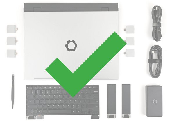
Replacement Mainboards come with a pre-installed heatsink but don't come with pre-installed storage, memory, or Wi-Fi modules. This guide will show how to transfer them to your new Mainboard.
If you're running Windows:
- Make sure you back up your data.
- If you’re running a Pro version of Windows, follow these directions to suspend BitLocker.
- If you're running a Home version of Windows and have enabled Windows Device Encryption, you'll want to disable it. To disable it, press Win + I to open Settings and select Privacy & Security. Then, click on Device Encryption on the right panel and toggle the setting to Off.
- Find your product key or link your Windows license to a Microsoft account to make sure you can re‑activate Windows after the change.
Some photos in this guide may contain slight visual discrepancies, but they won't affect the procedure.
Tools
Parts
No parts specified.
-
-
If you are upgrading from AMD Ryzen™ 7040 Series to AMD Ryzen™ AI 300 Series, you'll need to first update your Input Module firmware following the instructions here.
-
Unplug all cables and fully shut down your laptop.
-
-
-
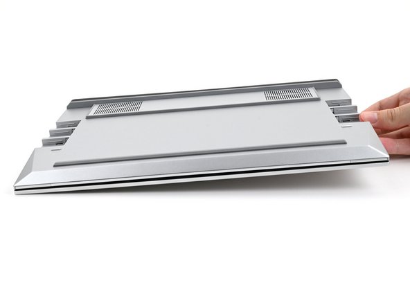
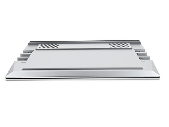
Close the laptop and flip it over.
-
-
-
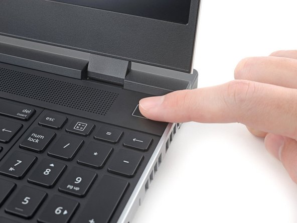
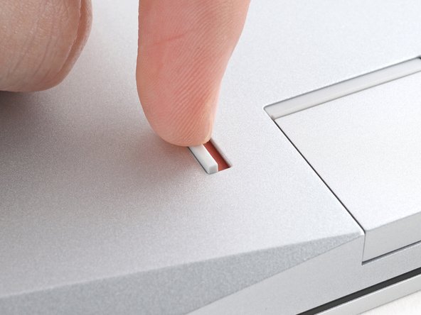
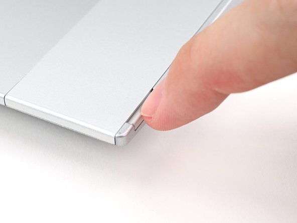
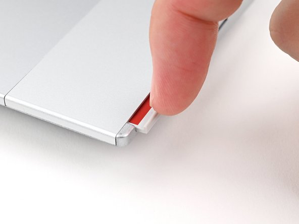
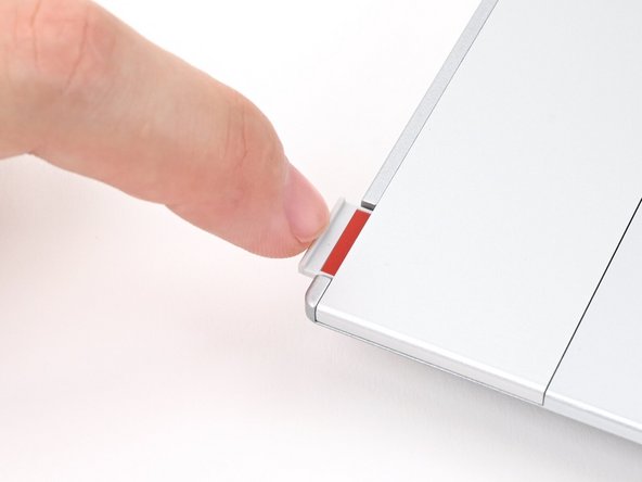
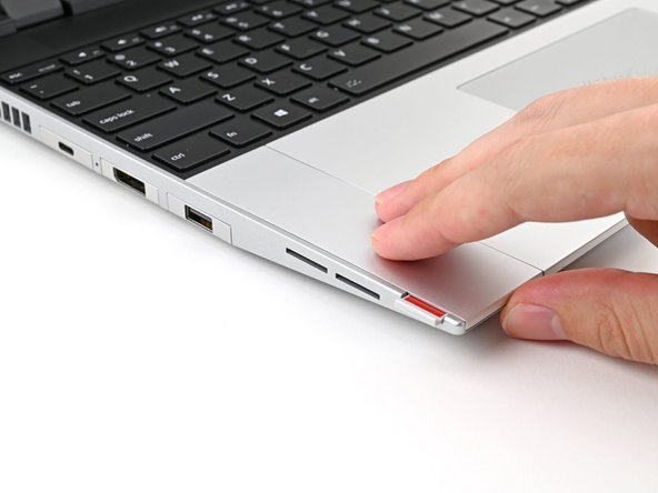
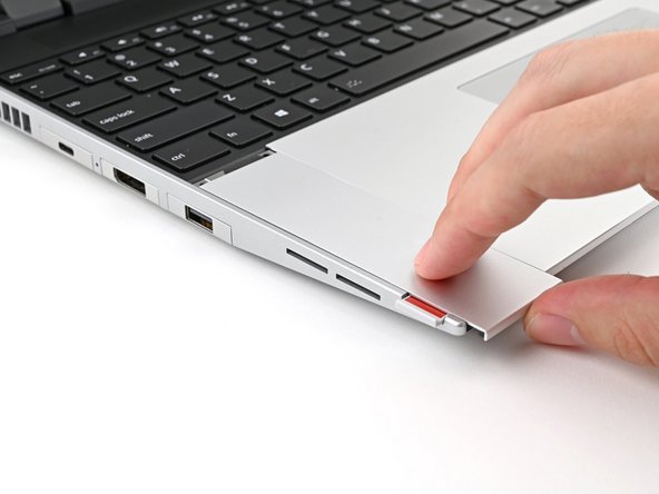
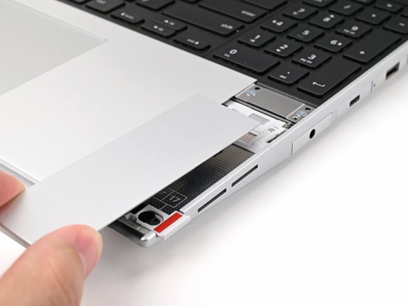
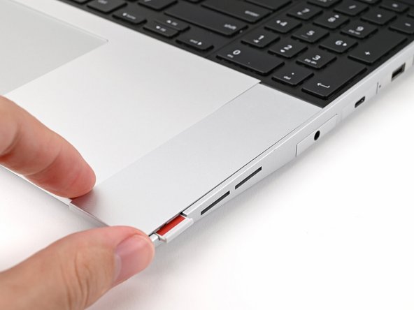
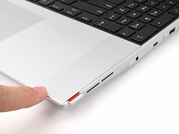
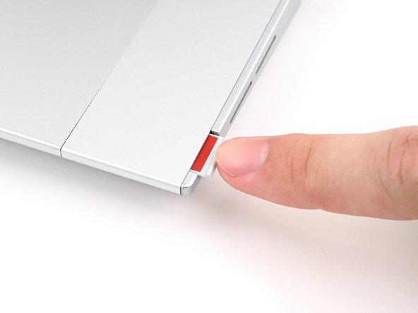
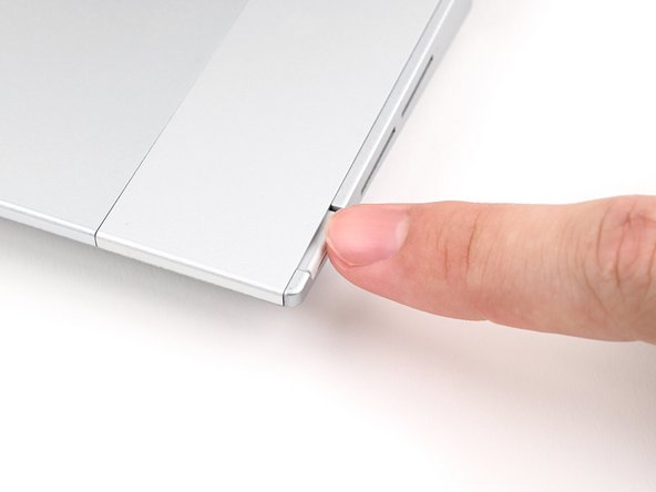
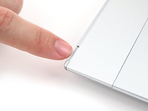
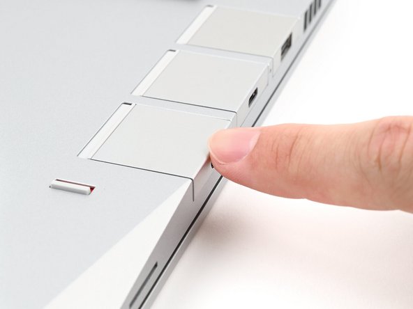
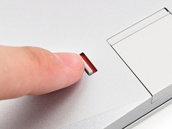
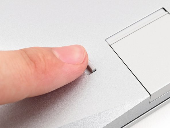
Use your finger to flip the Expansion Card latches into the unlocked position.
-
The latch displays a red bar when it's unlocked.
-
-
-
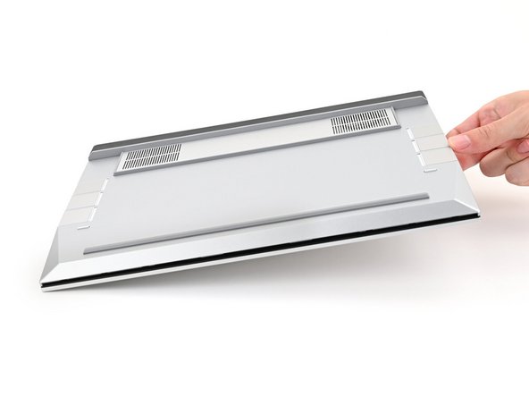
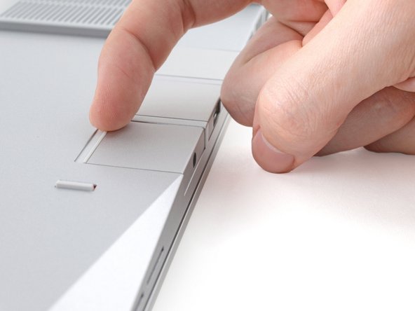
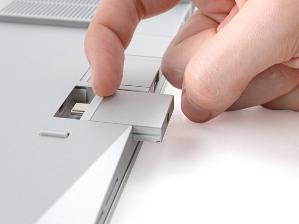
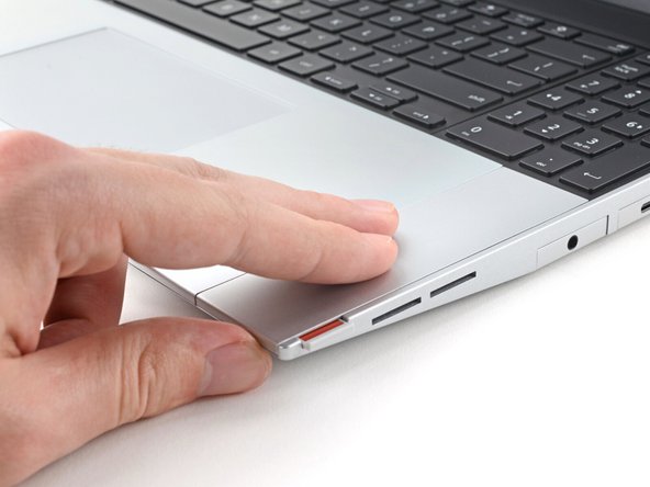
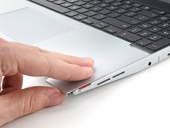
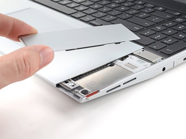
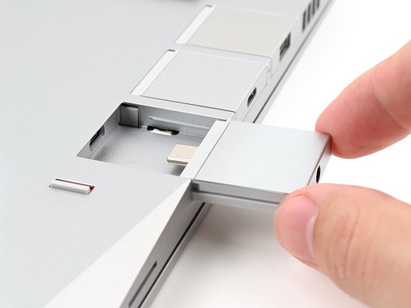
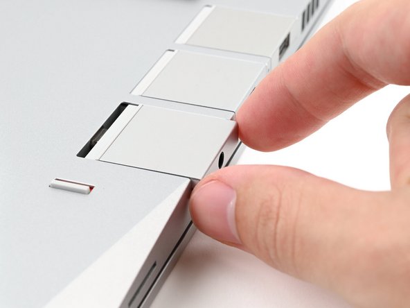
Grip the lip of the Expansion Card with your fingers.
-
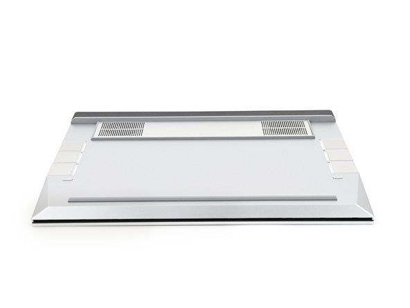
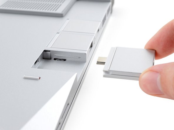
Pull the Expansion Card out of its slot and remove it.
-
This might take some initial force. If you're having trouble, make sure the locking tab is properly unlocked.
-
Repeat for all remaining Expansion Cards.
-
-
-
Flip your laptop over and open it.
-
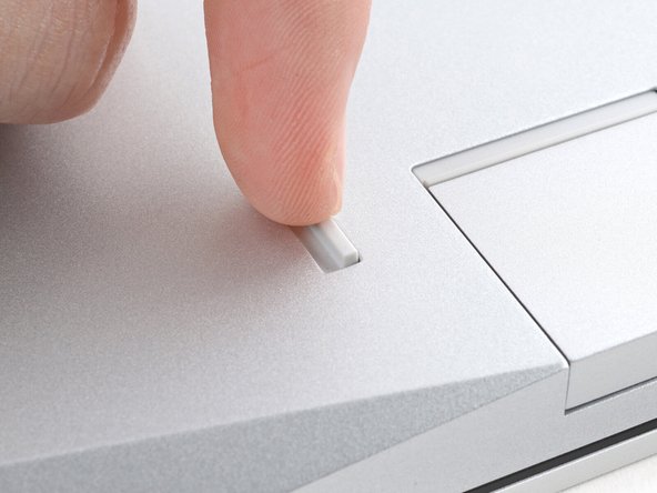
Use your fingernail to pull out the two Input Module latches and unlock them.
-
The latch will show red if it's unlocked.
-
-
-
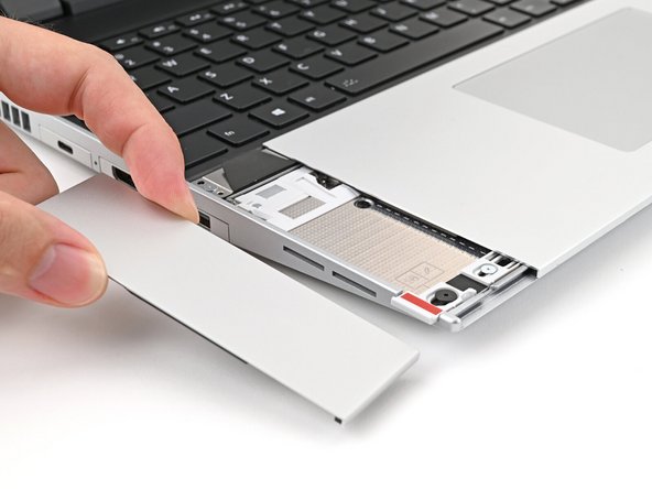
Use your fingers to slide the Touchpad Spacer toward the bottom edge of the laptop and unclip it.
-
If you're having trouble, check if the corresponding Input Module latch is properly unlocked.
-
Lift the Touchpad Spacer off the laptop and remove it.
-
-
-
Repeat the same procedure for the other touchpad spacer.
-
-
-
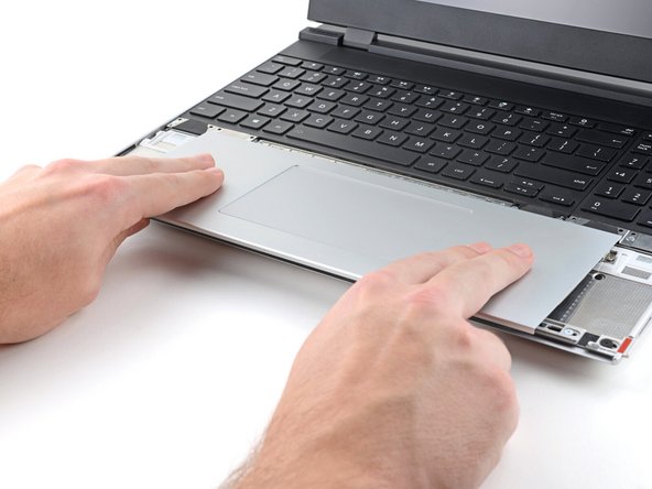
Use your fingers to slide the Touchpad Module toward the bottom edge of the laptop and disconnect it.
-
If you're having trouble, check if the Input Module latches are properly unlocked.
-
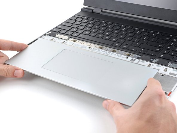
Lift the Touchpad Module and remove it.
-
-
-
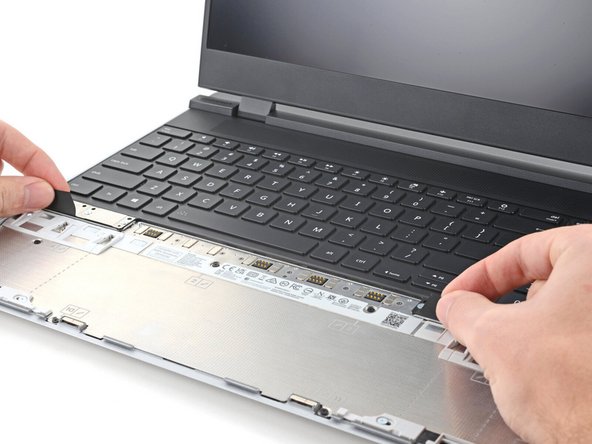
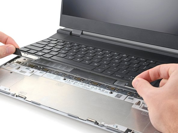
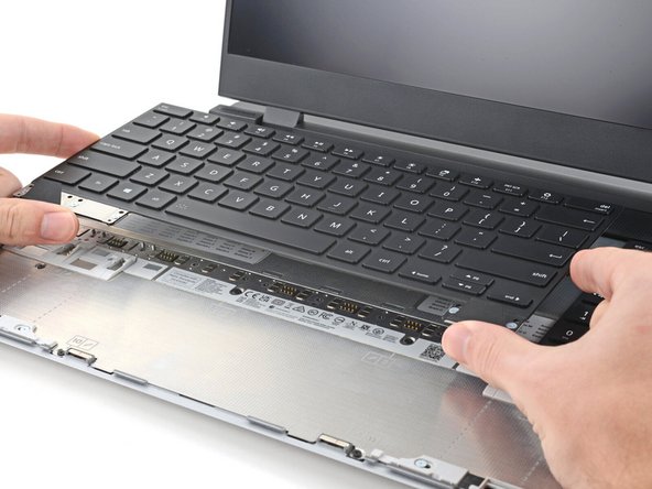
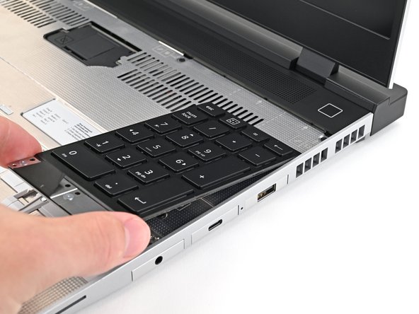
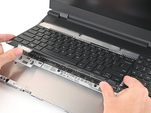
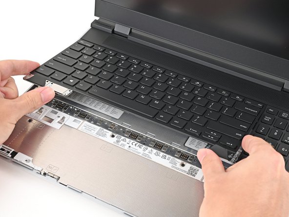
The keyboard is held in place with strong magnets. Apply gradually increasing force to avoid having the keyboard violently eject.
-
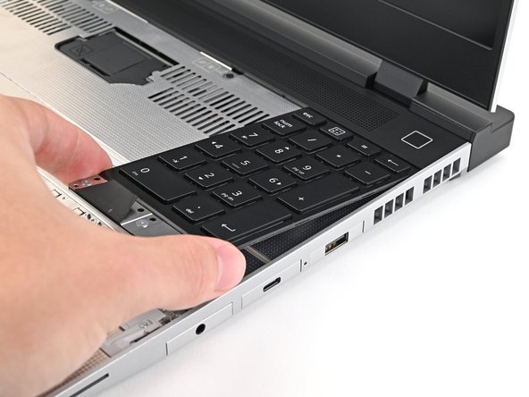
Grip the two pull tabs along the bottom of the keyboard and lift until its magnets release.
-
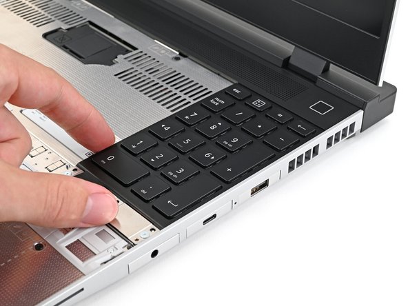
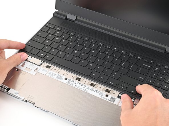
Remove the keyboard.
-
-
-
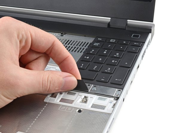
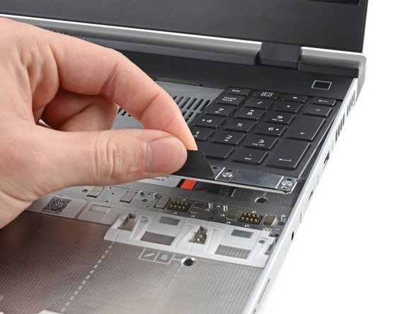
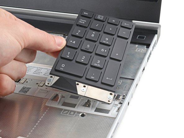
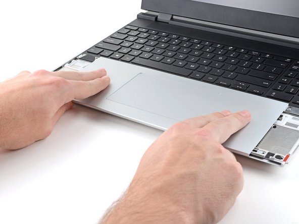
Your Input Module(s) might be different, but the procedure to remove them is the same.
-
Grip the pull tab at the bottom of the Input Module and lift until its magnets release.
-
Remove the Input Module.
-
Repeat for any remaining Input Modules.
-
-
-
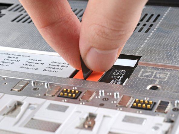
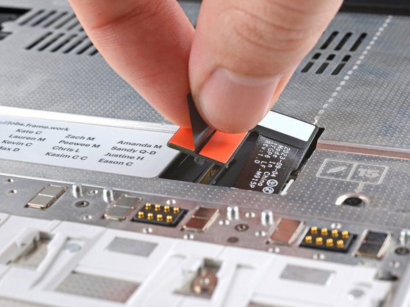
Grip the black pull tab on the Mid Plate cable press connector and lift up to disconnect it.
-
-
-
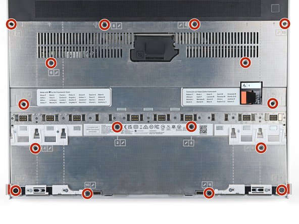
The Mid Plate screws are ordered from 2–17 (number 1 is the press connector). You don't have to follow the order, but you can use it to help keep track of the screws you've loosened.
-
Use your Framework Screwdriver to loosen the 16 captive T5 Torx screws securing the Mid Plate.
Maybe you should also mention that we are NOT supposed to REMOVE the screws, just make them loose.
For somebody that did some (albeit crappy) DIY laptop disassembly in the past, that fact is VERY easy to glance over. Usually, when told to loosen the screws, it is somewhat implicitly expected to remove them as well.
I was wondering why the first screw I tried to remove just wouldn't come off even when loose (some of them do, some of them don't), and I hope that I didn't damage something by attempting to remove the loose screw by force (after rechecking multiple times that it is indeed loose).
I even had a place prepared to put the screws into... 👀
-
-
-
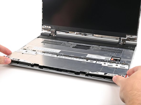
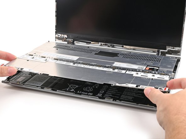
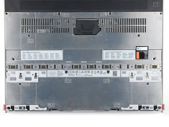
Use your fingers to lift the Mid Plate off the laptop and remove it.
-
-
-
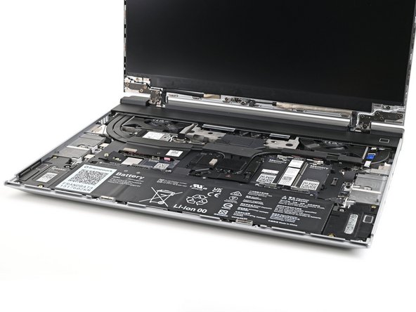
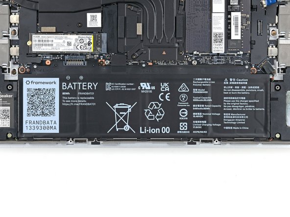
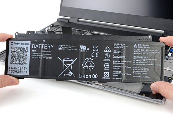
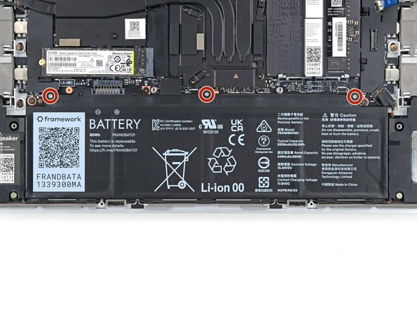
Use your Framework Screwdriver to loosen the three captive T5 Torx screws securing the battery.
-
-
-
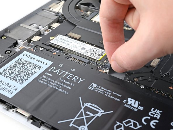
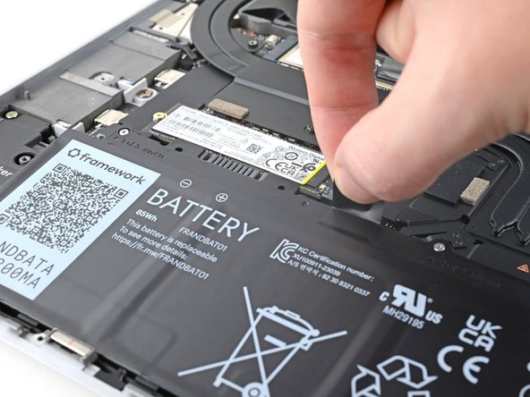
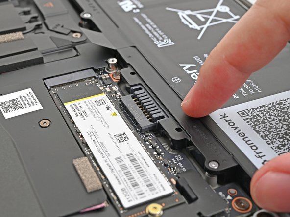
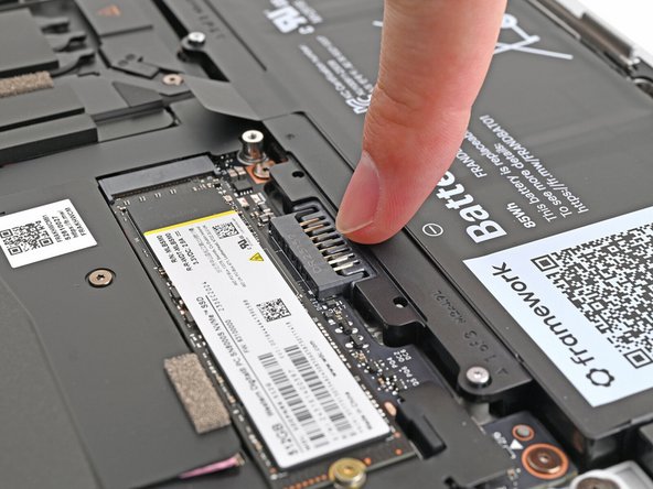
Grip the black pull tab at the top of the battery and lift to disconnect the battery connector.
-
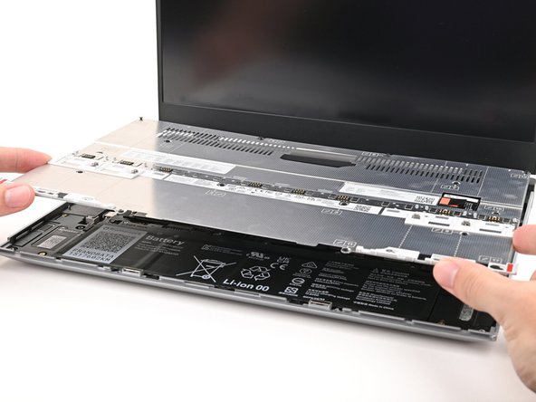
Remove the battery.
-
-
-
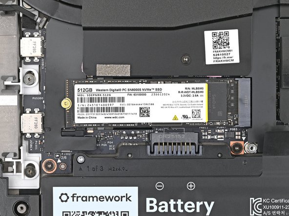
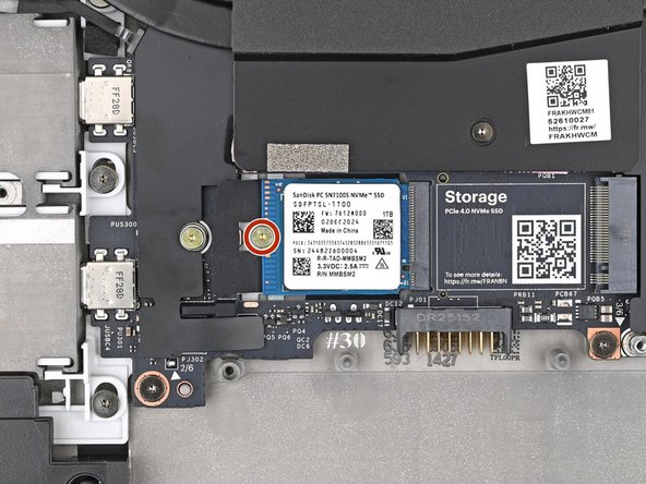
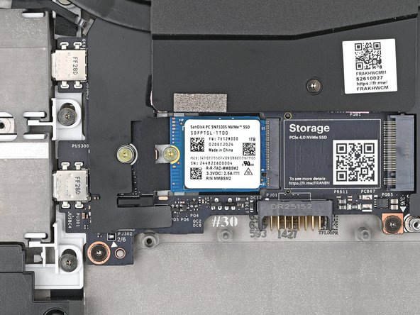
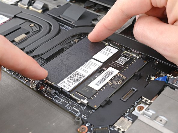
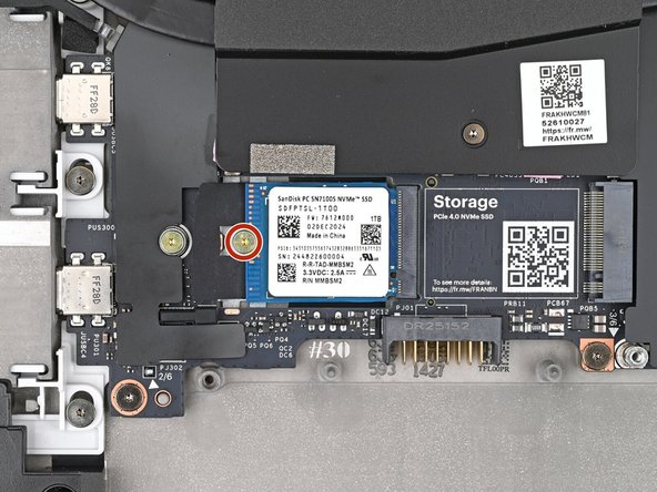
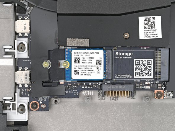
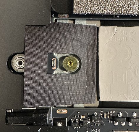
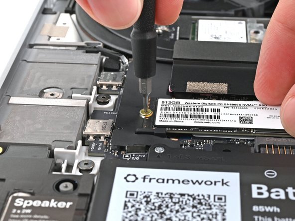
Use your Framework Screwdriver to remove the 2 mm‑long T5 Torx screw securing the SSD.
-
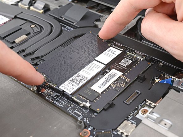
The SSD might pop up at a shallow angle when you remove the screw.
-
-
-
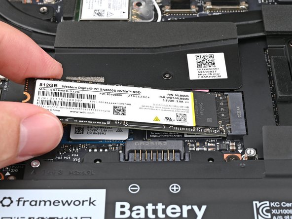
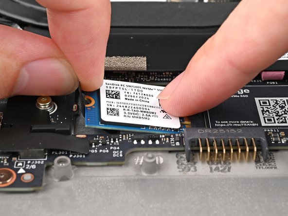
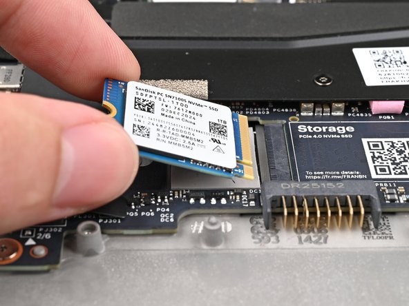
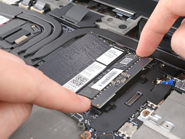
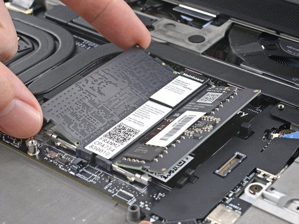
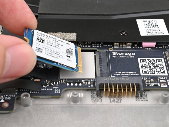
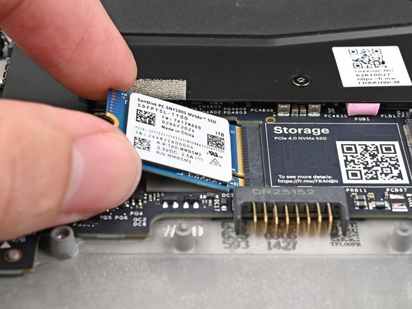
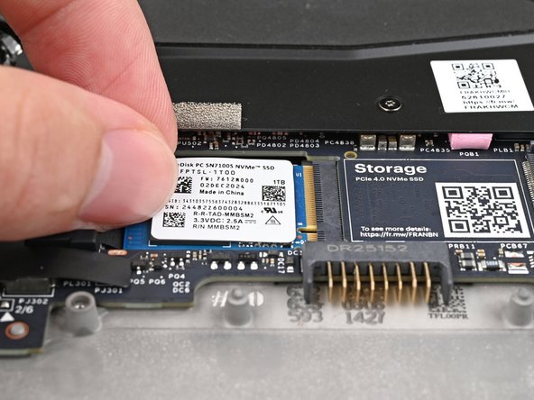
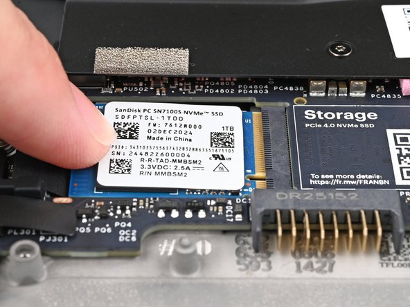
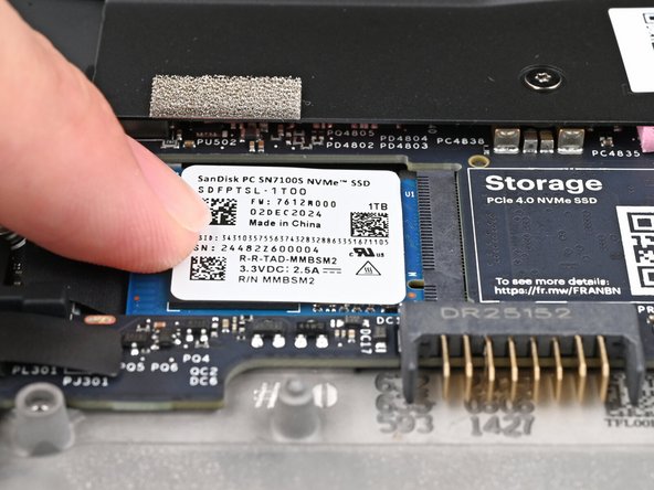
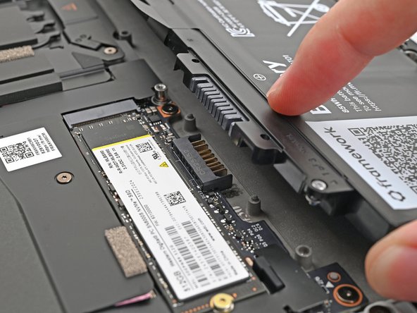
Grip the end of the SSD with the screw hole and slide it out of its socket.
-
Remove the SSD.
-
-
-
If you have a secondary SSD installed, follow the next two steps.
-
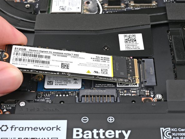
Use your Framework Screwdriver to remove the 2 mm‑long T5 Torx screw securing the secondary SSD.
-
-
-
While pulling up on the black tab underneath the SSD, use your finger to slide the SSD out of its socket.
-
Avoid touching the gold contacts. Only press on the top label or the edges of the SSD.
-
-
-
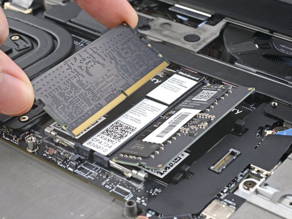
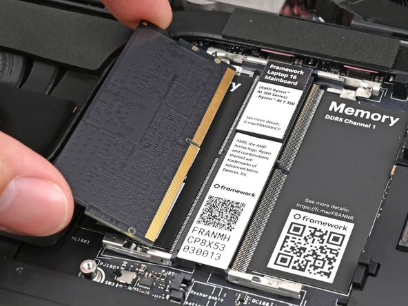
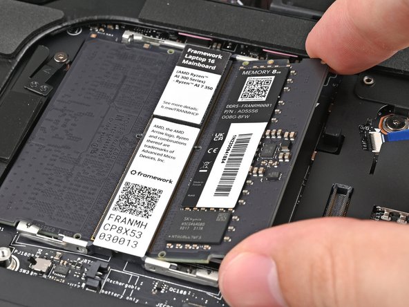
Push the two metal arms on each side of the RAM stick outward until they disengage and the stick pops up at a shallow angle.
-
Repeat for the other RAM stick.
-
-
-
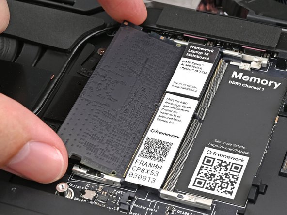
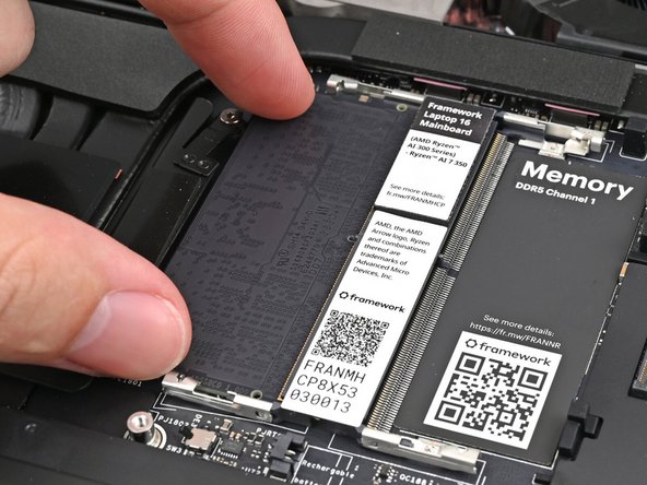
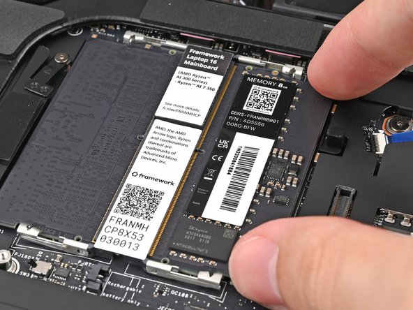
Slide the RAM stick out of its socket and remove it.
-
Repeat for the other RAM stick.
-
-
-
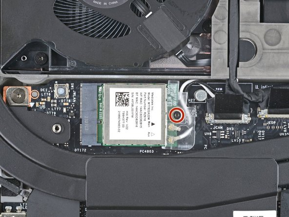
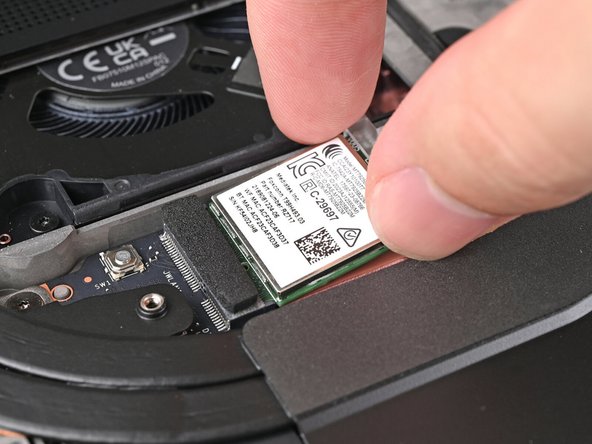
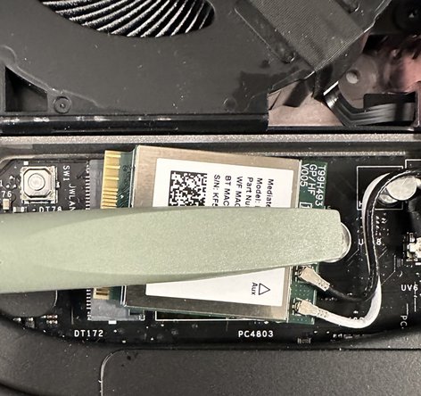
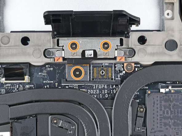
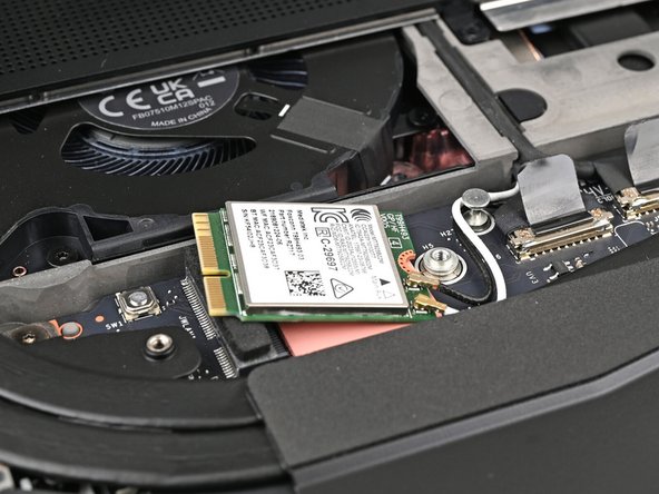
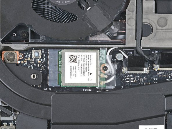
Use your Framework Screwdriver to loosen the captive T5 Torx screw securing Wi-Fi module.
-
The module might pop up at a shallow angle when you loosen the screw.
-
-
-
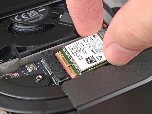
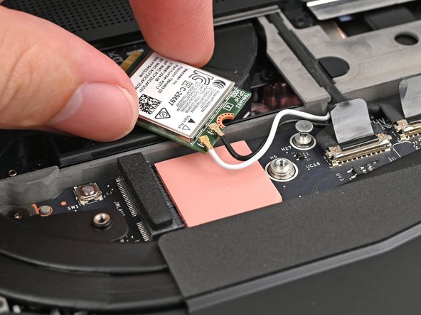
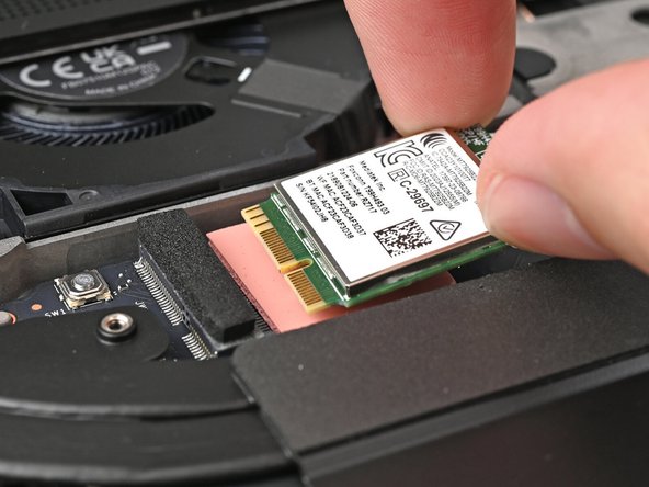
Grip the end of the Wi-Fi module with the screw hole and slide it out of its socket.
-
Don't pull the module too far from its socket, as it's still connected by two cables.
-
-
-
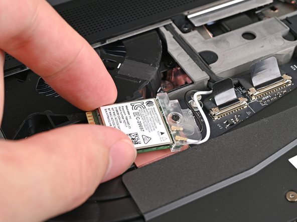
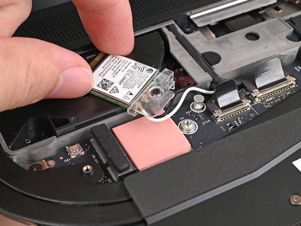
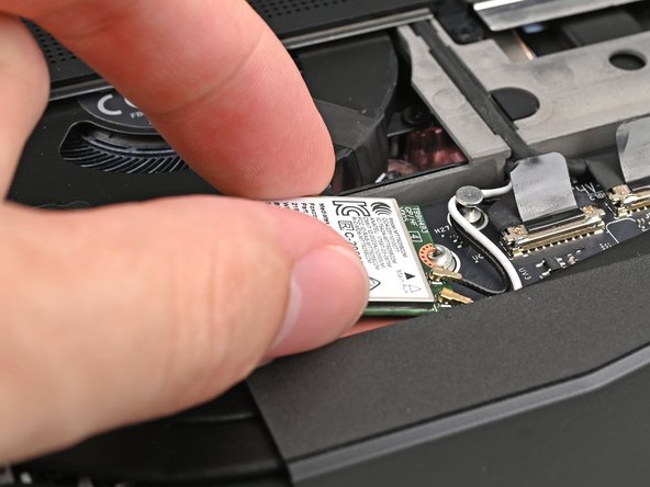
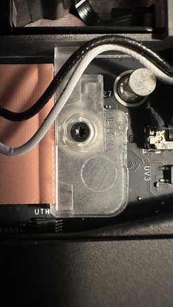
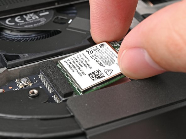
Rotate the Wi-Fi module towards the top of the laptop to keep it out of the way of the Mainboard.
-
If the antenna cables disconnect, follow these steps to reconnect them.
-
-
-
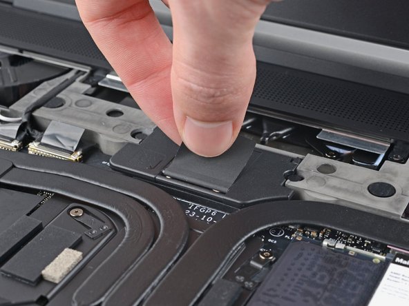
Lift the interposer door by its black pull tab and let it rest upright.
-
-
-
If you have the Graphics Module installed, your interposer will have four screws. If you have the Expansion Bay Shell installed, you'll have three screws instead.
-
If you have the Graphics Module, use your Framework Screwdriver to loosen the four captive T5 Torx screws securing the interposer.
-
If you have the Expansion Bay Shell, use your Framework Screwdriver to loosen the three captive T5 Torx screws securing the interposer.
-
-
-
Lift the interposer by its pull tab and remove it.
-
-
-
Use your Framework Screwdriver to loosen the two captive T5 Torx screws securing the module in the Expansion Bay.
-
Close the interposer door before continuing.
-
-
-
Close your laptop and flip it over.
-
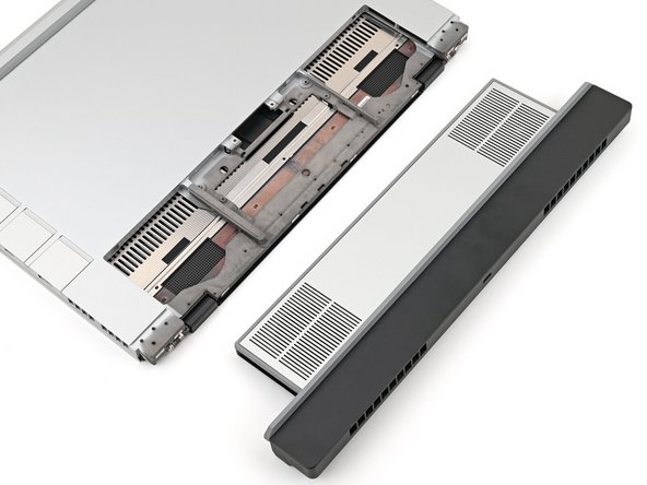
Slide the Expansion Bay Module out of the laptop and remove it.
-
The module should slide out easily. If you feel any resistance, check if the screws holding it in place are fully loosened.
-
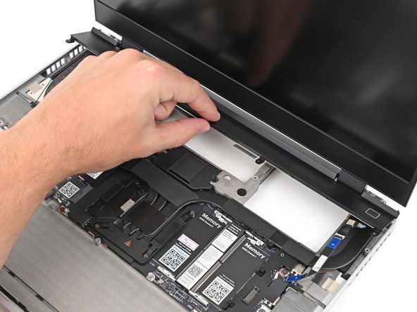
Reopen your laptop and flip it over.
It may be worth temporarily moving the Wi-Fi card back over its connector to provide a bit more clearance with the screen when closing the laptop.
Paul Wilson - Open Reply
-
-
-
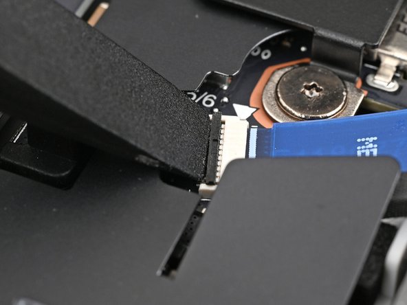
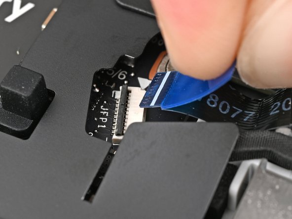
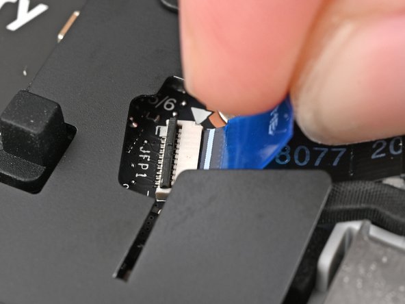
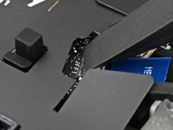
Use the flat end of a spudger, or a clean fingernail, to lift up the locking tab on the fingerprint sensor ZIF connector next to the memory.
-
-
-
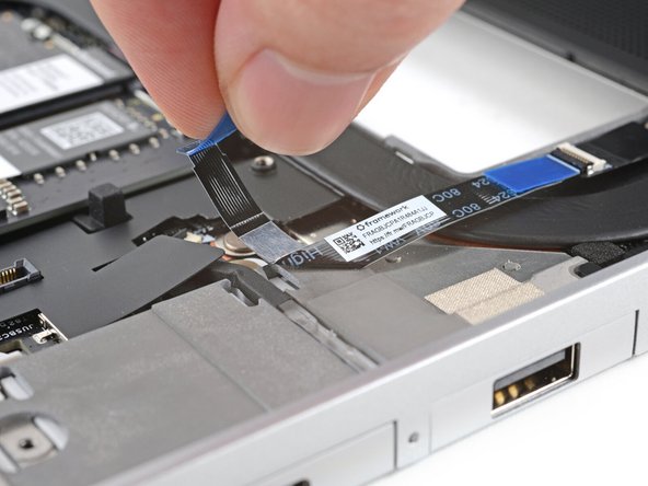
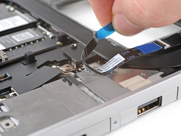
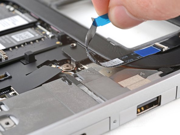
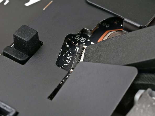
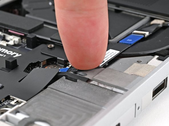
The fingerprint sensor cable is lightly adhered to the laptop's frame.
-
Use your fingers to peel the fingerprint sensor cable away from the frame and separate the adhesive.
-
-
-
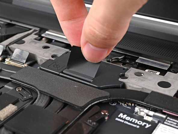
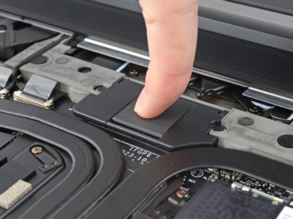
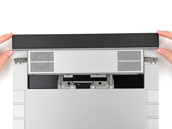
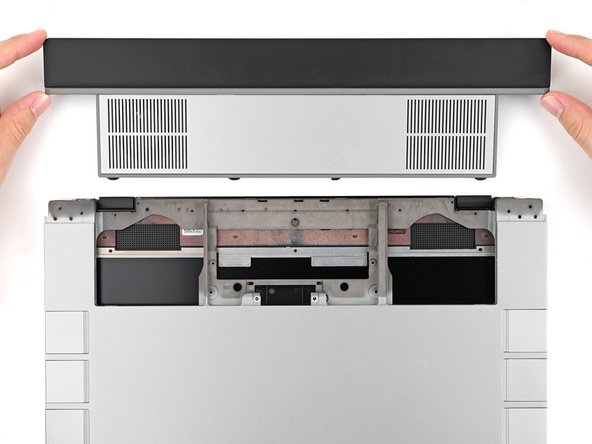
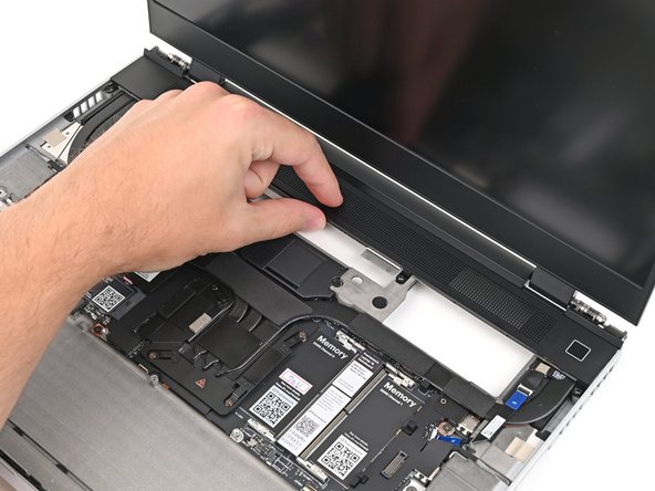
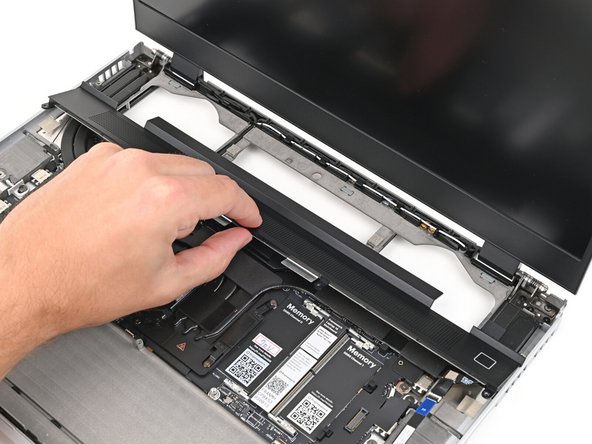
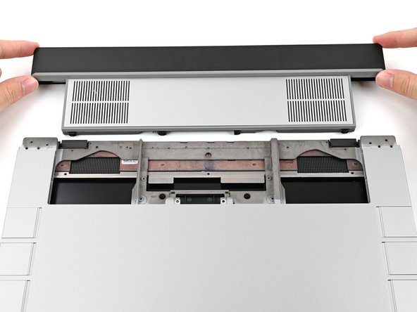
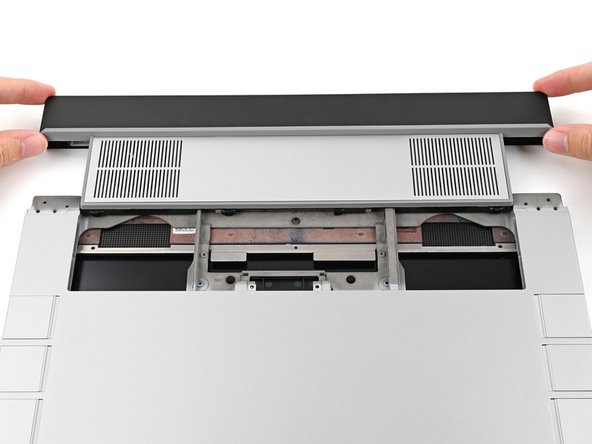
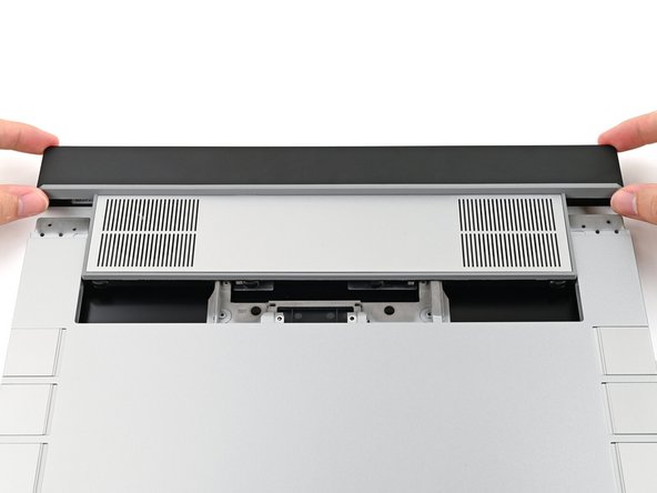
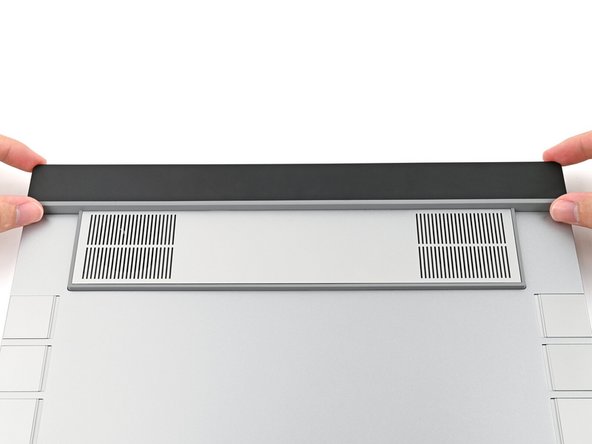
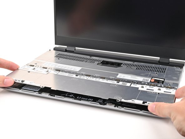
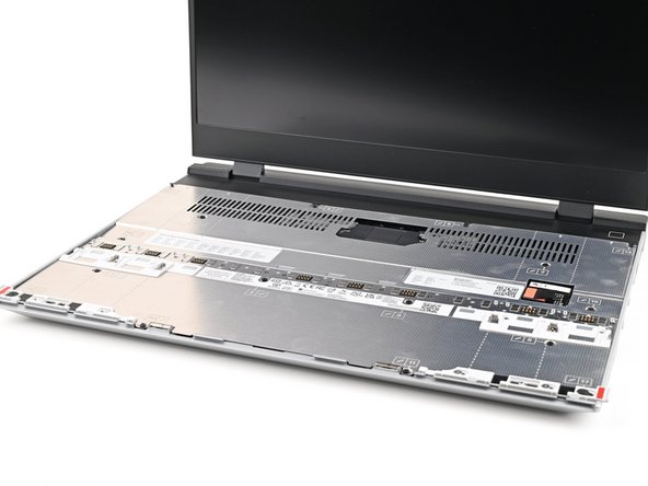
The ventilation plate is held in place with magnets.
-
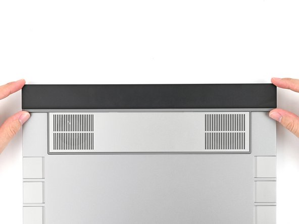
Lift the bottom of the ventilation plate and pull it away from the laptop until the magnets release.
-
Remove the ventilation plate.
-
-
-
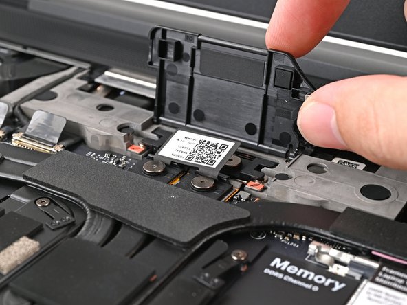
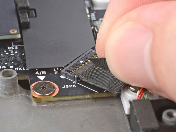
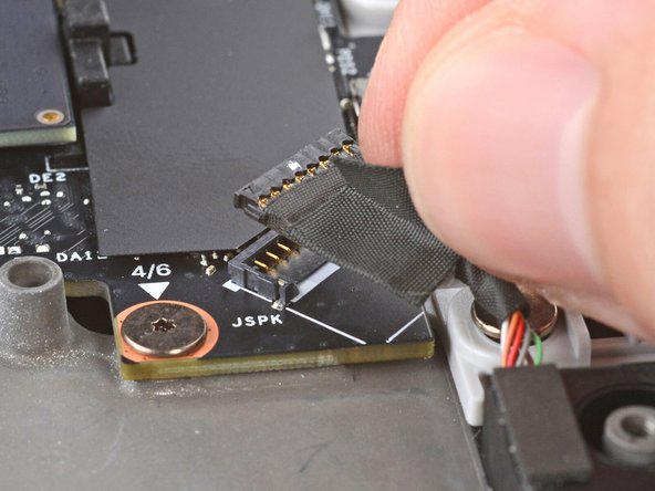
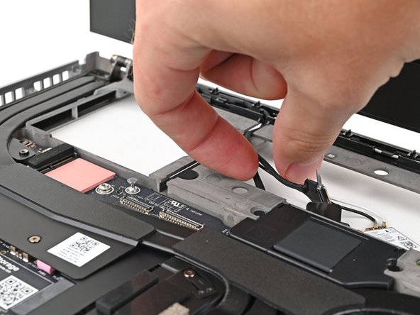
Lift the speaker cable connector by its black pull tab and disconnect it.
-
-
-
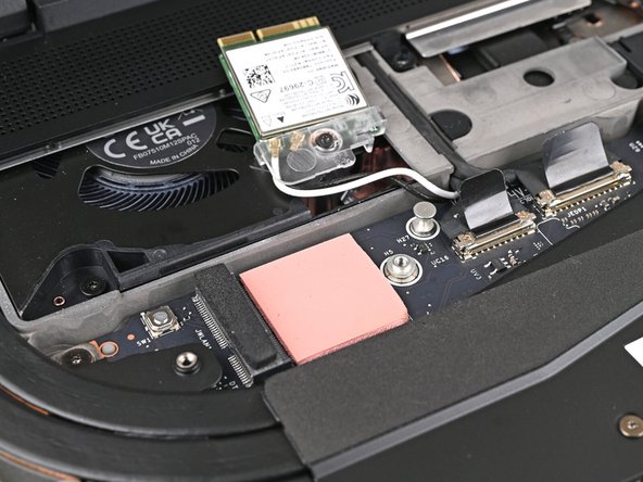
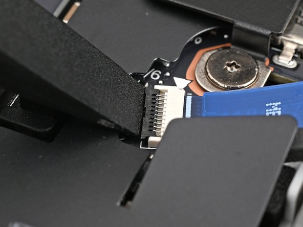
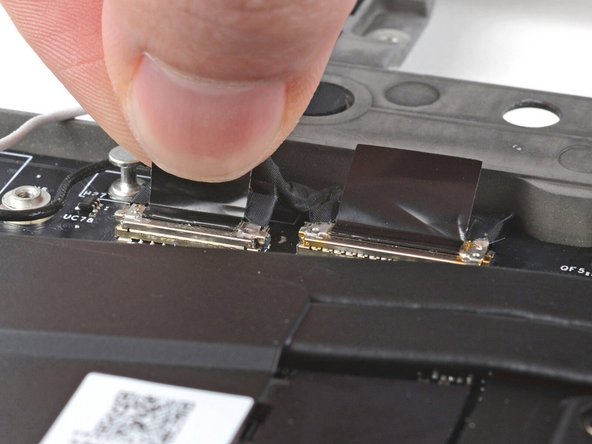
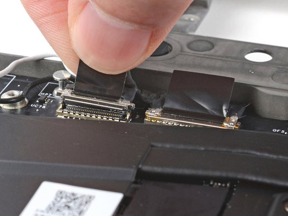
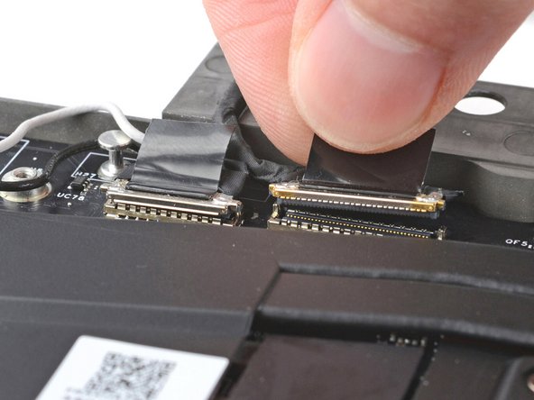
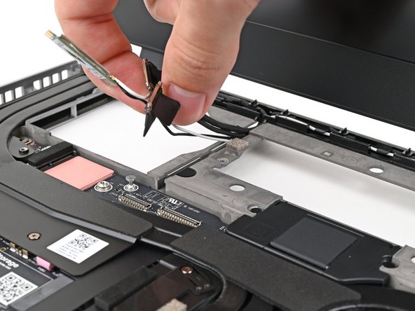
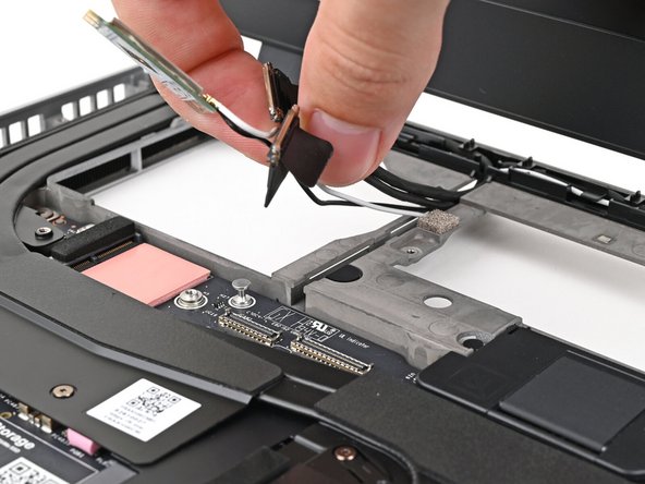
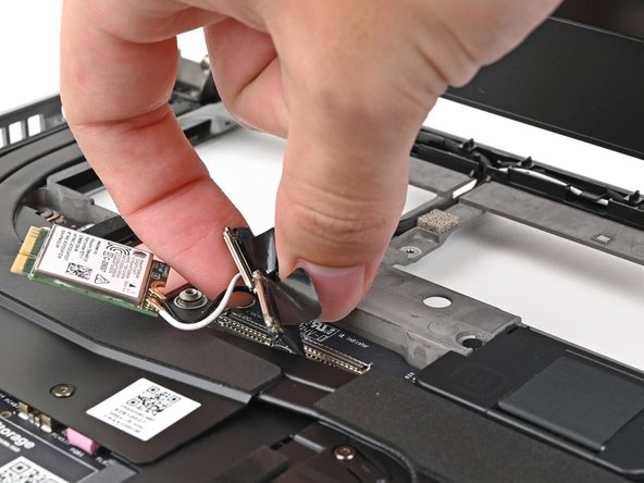
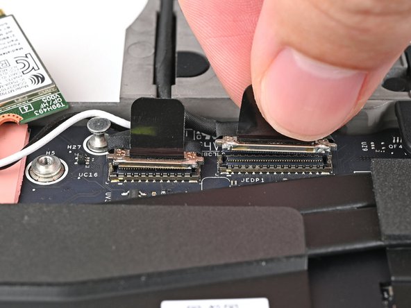
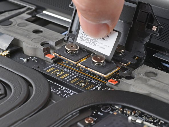
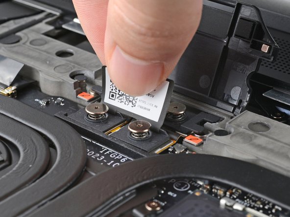
Grip the webcam cable connector to the right of the Wi-Fi module slot by its pull tab and lift up to disconnect it.
-
Repeat for the display cable connector next to it.
-
-
-
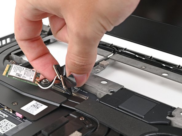
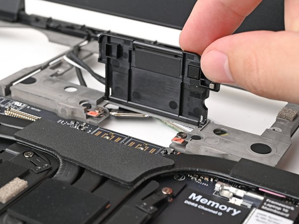
Lift the display, webcam, and Wi-Fi module cables out of their slot in the frame enough to give room for the Mainboard to lift straight up.
-
Optionally, you can tuck the cables underneath the frame.
-
-
-
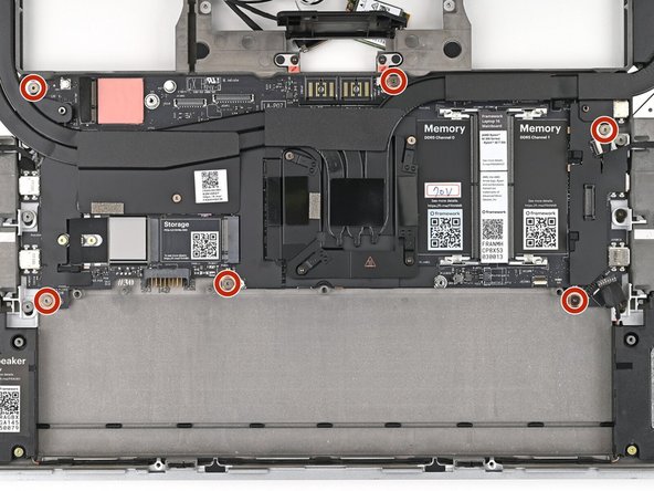
Lift up the interposer door to reveal the screw underneath.
-
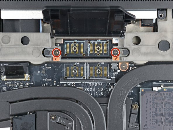
The Mainboard screws are ordered from 1–6. You don't have to follow the order, but you can use it to help keep track of the screws you've removed.
-
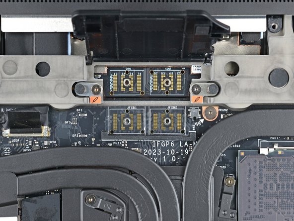
Use your Framework Screwdriver to remove the six 2 mm‑long T5 Torx screws securing the Mainboard.
-
-
-
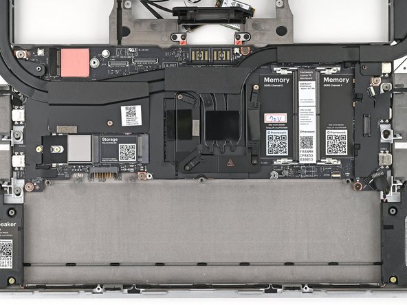
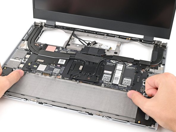
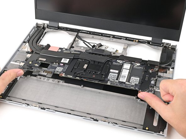
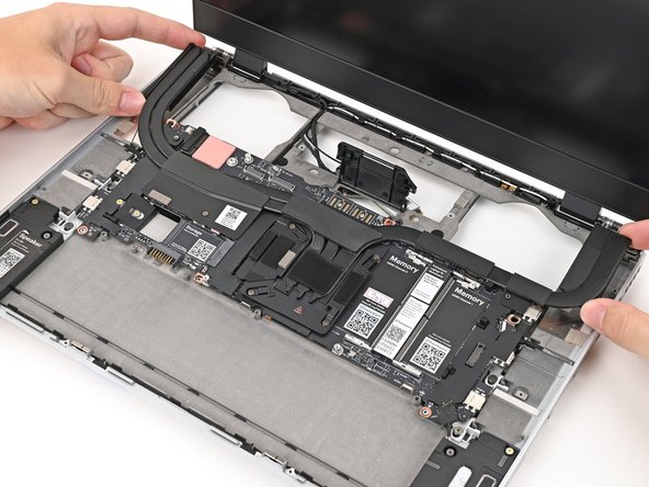
Use your fingers to lift the bottom edge of the Mainboard enough to grip its edges.
-
Lift the Mainboard off its alignment pegs and remove it.
Ensure the display is opened no more than 90 degrees. Exceeding this angle can cause the laptop to fall backward onto the screen when the logic board is removed.
Paul Wilson - Open Reply
-
-
-
Congratulations on completing disassembly! The remaining steps will show how to reassemble your Framework Laptop.
-
-
-
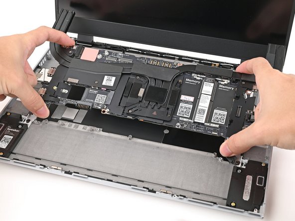
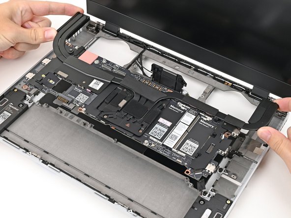
Grab the Mainboard by the curving pipes of its heatsink.
-
Place the Mainboard into the laptop and onto its alignment pegs.
-
Make sure all of the cables are above the Mainboard before continuing.
-
-
-
Use your Framework Screwdriver to install the six 2 mm‑long T5 Torx screws securing the Mainboard.
-
-
-
Route the display, webcam, and Wi-Fi module cables into their slots in the frame.
-
-
-
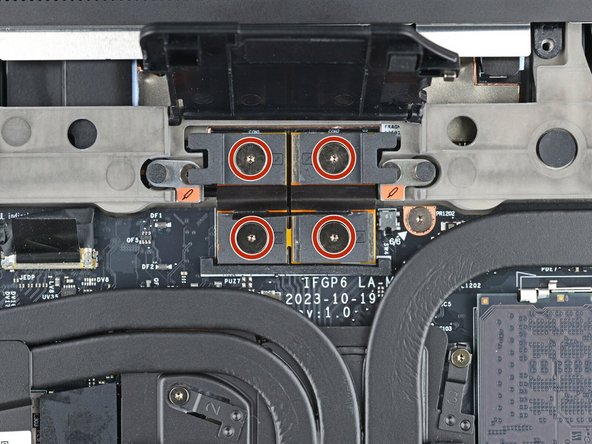
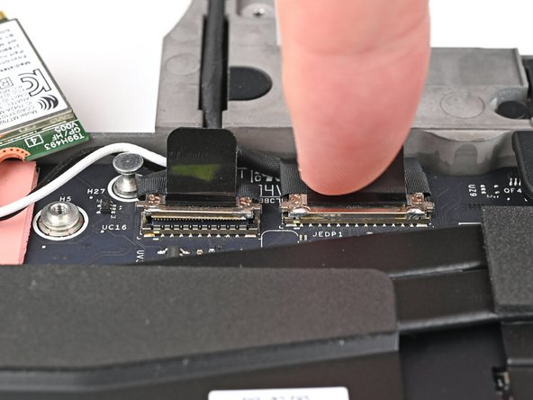
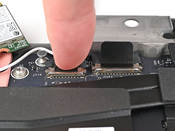
Press the two display connectors straight down into their sockets to connect them.
-
-
-
Press the speaker cable connector straight down into its socket to connect it.
-
-
-
Lay the ventilation plate along the top edge of the laptop and let its magnets pull into place.
-
-
-
Use tweezers, or your fingers, to grip the blue pull tab and slide the fingerprint sensor cable straight into its socket.
-
-
-
Use the flat end of a spudger, or a clean fingernail, to press down the locking tab on the fingerprint sensor ZIF connector.
-
-
-
Press the fingerprint sensor cable to the frame to re-adhere it.
-
-
-
Close your laptop and flip it over.
-
Align the Expansion Bay Module with its slot in the laptop.
-
Check that the module sits evenly with the rail on the outside edges of the slot.
-
Check that the two center rails are threaded between the fans.
-
-
-
While keeping the module level with the laptop, slide it into its slot.
-
The module should slide in easily. If you feel any resistance, pull the module out and realign it.
-
You should hear an audible "click" when the module's clips snap into place.
-
Reopen your laptop and flip it over.
-
-
-
Use your Framework Screwdriver to tighten the two captive T5 Torx screws securing the Expansion Bay Module.
-
-
-
Place the interposer over its spot between the Mainboard and the module.
-
Depending on if you're installing a Graphics Module or the Expansion Bay Shell, the interposer should be oriented so either rubber grommets or metal tabs cover the Expansion Bay screws.
-
-
-
If you have the Graphics Module installed, your interposer will have four screws. If you have the Expansion Bay Shell installed, you'll have three screws instead.
-
If you have the Graphics Module, use your Framework Screwdriver to tighten the four captive T5 Torx screws securing the interposer.
-
If you have the Expansion Bay Shell, use your Framework Screwdriver to tighten the three captive T5 Torx screws securing the interposer.
-
Close the interposer door.
-
-
-
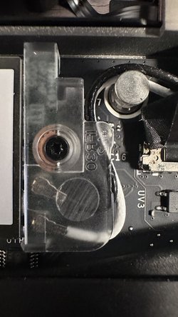
Rotate the Wi-Fi Module back into place, making sure the antenna cables wrap around their silver peg on the Mainboard and tuck underneath the heat sink.
-
-
-
Hold the Wi-Fi module by its edges. Don't touch the gold contacts with your fingers. If you do, wipe the contacts with a clean, lint-free cloth to remove any finger oils.
-
Align the Wi-Fi module's gold contacts and notch with the socket on the Mainboard.
-
Insert the Wi-Fi module into the socket at a shallow angle. The gold contacts should mostly be covered by the socket.
-
The Wi-Fi module fits into the socket in one orientation. If it doesn't fit, try flipping the module.
-
-
-
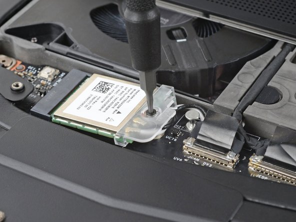
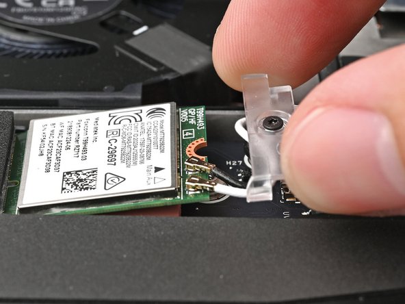
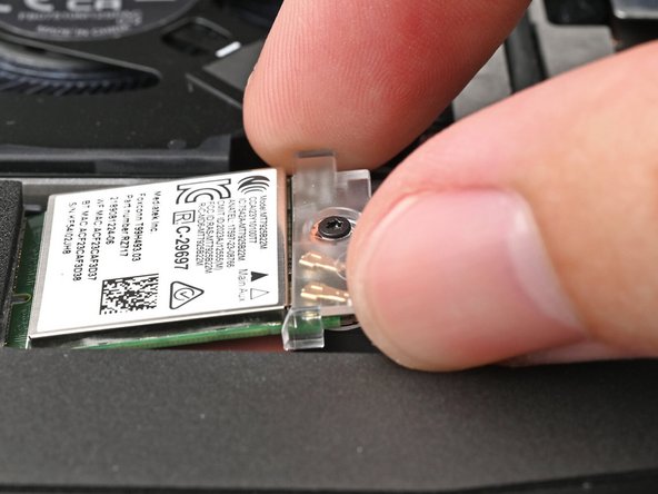
Slide the clear Wi-Fi module cover on the module and align its screw with the screw hole cutout.
-
-
-
Use your Framework Screwdriver to tighten the captive T5 Torx screw securing Wi-Fi module.
Due to the slightly different design of the bracket that came with the motherboard, the wires need to be routed a bit differently.
Paul Wilson - Open Reply
-
-
-
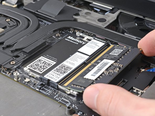
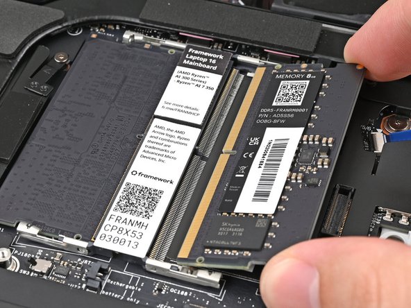
Hold the memory module by its edges. Don't touch the gold contacts with your fingers. If you do, wipe the contacts with a clean, lint-free cloth to remove any finger oils.
-
Orient the module with its label facing down and align the gold contacts with the left socket labeled DDR5 Channel 0.
-
Insert the contact edge into the socket at a shallow angle. The gold contacts should mostly be covered by the socket.
-
Press the edges of the memory module down until the side clips lock it in place.
-
-
-
If you're using two memory modules, orient the other module so its label is facing upward and repeat the previous step for the other socket labeled DDR5 Channel 1.
-
-
-
Hold the SSD by its edges. Don't touch the gold contacts with your fingers. If you do, wipe the contacts with a clean, lint-free cloth to remove any finger oils.
-
Align the SSD's gold contacts with its socket.
-
Insert the SSD partially into the socket at a shallow angle. You should still be able to see most of the gold contacts.
-
Press the SSD flat to the Mainboard.
-
-
-
While keeping the SSD flat to the Mainboard, push it into its socket until its golden contacts are completely covered.
-
-
-
Use your Framework Screwdriver to install the 2 mm‑long T5 Torx screw securing the SSD.
-
-
-
Hold the SSD by its edges. Don't touch the gold contacts with your fingers. If you do, wipe the contacts with a clean, lint-free cloth to remove any finger oils.
-
Insert the SSD into the socket at a shallow angle. The gold contacts should mostly be covered by the socket.
-
The SSD fits into the socket in one orientation. If it doesn't feel like it fits, try flipping the module.
-
-
-
While holding the SSD flat to the Mainboard, use your Framework Screwdriver to install the 2 mm‑long T5 Torx screw securing the SSD.
-
-
-
Align the battery connector over its socket and lay the battery into its well.
-
Lightly press the battery down to connect it.
-
-
-
Use your Framework Screwdriver to tighten the three captive T5 Torx screws securing the battery.
-
-
-
Place the Mid Plate on the laptop, making sure it sits evenly on its alignment pegs.
-
-
-
Use your Framework Screwdriver to tighten the 16 captive T5 Torx screws in order (starting with 2) to secure the Mid Plate evenly.
-
-
-
Align the Mid Plate cable press connector over its socket and press down to connect it.
-
-
-
Your Input Module(s) might be different, but the procedure to remove them is the same.
-
Align the top edge of the Input Module with the top edge of the laptop.
-
Lay the Input Module on the laptop and let the magnets pull the keyboard into place
-
Make sure the Input Module is seated properly on its alignment pegs and sits flush with the edges of the laptop.
-
Repeat for any remaining Input Modules.
This step is about installing the modules again, but the very first sentence mentions ".. to remove them...". That should say: "... to install them..."
Thijs Marinussen - Open Reply
-
-
-
Align the top edge of the keyboard with the top edge of the laptop.
-
Lay the keyboard on the laptop and let the magnets pull the keyboard into place
-
Make sure the keyboard is seated properly on its alignment pegs and sits flush with the edges of the laptop.
-
-
-
Place the Touchpad Module flat on its cutout so its clips are properly aligned.
-
Press the Touchpad Module down and slide it into place so it lines up evenly with the bottom edge of the laptop.
-
-
-
Place the Touchpad Spacer over its spot on the laptop with the bottom edge overhanging slightly.
-
Slide the Touchpad Spacer towards the top of the laptop to secure it.
-
Repeat the same procedure for the other Touchpad Spacer.
-
-
-
Push the Input Module latches back into place to lock them.
-
-
-
Close the laptop and flip it over.
-
-
-
Slide an Expansion Card into an Expansion Card slot.
-
You don't need to unlock the latch to install the Expansion Cards—only when you want to remove them.
-
The Expansion Cards should click into place, and the front edge should be flush with the laptop.
-
Repeat for all remaining Expansion Cards.
-
-
-
Use your finger to flip both latches and lock the row of Expansion Cards above them.
-
-


You finished fixing your Framework Laptop!
Take your e-waste to an R2 or e-Stewards certified recycler.
If you need help, contact Framework support.
You finished fixing your Framework Laptop!
Take your e-waste to an R2 or e-Stewards certified recycler.
If you need help, contact Framework support.
Cancel: I did not complete this guide.
9 other people completed this guide.
3 Comments
Be careful when installing the mainboard at the ends of the heatpipes. The ends are slightly under tension towards the inside. It is possible that the ventilation plate cannot be inserted correctly if the heatpipes are not at the bottom of the housing. If this is the case: The mainboard is inserted and the heatpipes are then pulled outwards very slightly and the mainboard then sinks all the way down.
When the upper SSD is installed, a plastic cover on the mainboard can get in the way. I removed the cover and only stuck it back on after I had installed the SSD. Otherwise, the SSD may be too high and the center plate may not sit properly.
Michael Graf - Resolved on Release Reply
- The GPU interposer appears to be a different design than it was when this guide was made. Mine had 4 screws to loosen instead of 3 and filled the whole space under the little door.
- Wifi card install wasn't obvious at first because the new motherboard came with the plastic part. (Similar comment above.)
- There is no step to reinstall the expansion cards. A step for that with the "don't install USB-A in these spots" picture would be helpful.
- There is no step to update the BIOS. The BIOS needed to be updated to current again once you are done since you just took the BIOS out with the old motherboard.
- The BIOS settings are on the motherboard, so reconnecting the battery may not be required.
I just followed this guide and the entire process went pretty smoothly considering I don't think of myself as a hardware person.
One point: you might suggest right at the beginning that Windows users make sure they've got a copy of their Bitlocker Recovery Key, because you need it when you start up again. Also you're going to have to remove and recreate your Windows Hello fingerprint, or at least I did.
Mark Rendle - Resolved on Release Reply