
Introduction
This guide will assist you with replacing the Liquid Metal on your Framework 16 with PTM 7958.
Tools
Parts
No parts specified.
-
-
Before beginning, make sure to shut down your Framework Laptop.
-
If the system is still powered on, you will see the chassis intrusion lights flashing red and blue when the Touchpad and Input Modules are removed.
-
-
-
To remove the Expansion Cards, first turn the Framework Laptop 16 over and open the Expansion Card Latches.
-
With the latches open the Expansion Cards should slide right out.
-
If the latches are open and the cards feel stuck, you can use the spudger end of your Framework Screwdriver to push them out.
-
-
-
In order to remove the Input Modules from the Framework Laptop 16, begin by opening the Input Deck Latches on each side of the Laptop.
-
When the latches are open you can see the red printed on the latch.
Perhaps a dumb question, but what are the initial conditions? i.e. Should my laptop be powered off, but still plugged in, before starting this?
Jonathan P Cox - Resolved on Release Reply
As far as I know, Framework recommends powering off the laptop before opening it. As far as keeping it plugged in, I would not recommend that as it may be an electrical hazard.
Soni -
-
-
-
To remove the Touchpad Spacers, slide them down and then they will lift away easily.
-
If there is resistance, make sure that the Input Deck Latches are open (see previous step).
-
-
-
After removing the Spacers, the Touchpad module can be removed in the same way. Gently slide it downwards from both sides and then lift away as shown.
-
-
-
To remove the Keyboard lift from the bottom using the pull tabs, and once lifted up the Keyboard module should lift out without resistance.
-
If your pull tabs are no longer attached, you can carefully use the spudger side of the Framework Screwdriver to lift the module away.
-
-
-
Remove your Input Modules or Spacers in the same way as the Keyboard, lifting from the bottom using the pull tabs as shown.
You will need to remove the module from the Expansion Bay to later remove the Ventilation Plate in step 10, which instructions are missing from this guide. Refer to the "Install Expansion Shell" and "Install Graphics Module (dGPU)" guides for instructions on removing the module from the Expansion Bay. It is better to remove the module from the Expansion Bay now, as the guides require you to close your laptop, and it is better done when the mid-plate is still installed and fastened, than when the screws are loose, or the mid-plate removed, IMHO.
Ádám Juhász - Open Reply
IMPORTANT: This comment meant for the Fingerprint Reader guide ONLY. I didn't realize at the time, that leaving a comment for a step appears across ALL GUIDES WITH THE SAME STEP.
-
-
-
Depending on if you have the Expansion Bay Shell or Graphics Module installed, you will have to remove it first. Follow the guide below to remove the specific module you have installed. Once removed, come back to this guide and continue to the next step.
-
To remove the "Expansion Bay Shell" from your Framework 16, please follow this guide: Remove Expansion Bay Shell
-
To remove the "Graphics Module" from your Framework 16, please follow this guide: Remove Graphics Module
Updated comment: @liam, before that you need to remove the mid-plate. @iroh, any chance you can add mid-plate step?
Patrick M. - Open Reply
@liam , I agree, but even before that you need to remove the mid-plate. @iroh , any chance you can add mid-plate and battery removal steps?
Patrick M. - Open Reply
-
-
-
Using the spudger side of your Framework Screwdriver, flip open the latch securing the Fingerprint Reader cable in place.
-
Using the pull tab, gently pull the Fingerprint Reader cable out of the socket on the Mainboard.
-
-
-
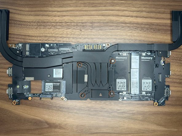
Since the Ventilation Plate is held in place by the Mid Plate and the module installed in the Expansion Bay, with both of these removed, you can now lift it away from the Bottom Cover.
-
As you lift the Ventilation Plate away, peel the light adhesive holding the Fingerprint Reader Cable onto the Bottom Cover as shown.
Step 7 to 11 from the Expansion Bay Shell Cover should be done before this step 10.
It was skipped in this guide.
Antoine Demblon - Open Reply
You may want to remove Expansion Bay Shell to get easier access to the plate.
Sven-Erik Petermann - Open Reply
In the video, top corner covers with framework logo are missing, the plate is behind these corners, not sure how to remove those.
Sven-Erik Petermann - Open Reply
-
-
-
Loosen the 3 fasteners, note that these are captive fasteners that will remain attached to the Battery.
-
Lift the pull tab up to disconnect the Battery then lift it out to remove it from the Bottom Cover.
-
-
-
Disconnect the Speaker cable from the Mainboard by pulling directly up using the pull tab as shown.
-
-
-
At the top of the Mainboard are three connectors to remove, from right to left these are the eDP (Display) cable, the Webcam Cable and the WiFi.
-
Disconnect the eDP and Webcam cables by pulling directly up on the pull tabs and unroute the cables slightly from their guides as shown to keep them out of the way of the Mainboard.
-
Remove the WiFi Bracket using the Torx T5 bit on your Framework Screwdriver and remove the WiFi Card as shown.
-
We recommend for this guide to keep the WiFi Module attached to the antenna cables as these can be difficult to reattach.
-
-
-
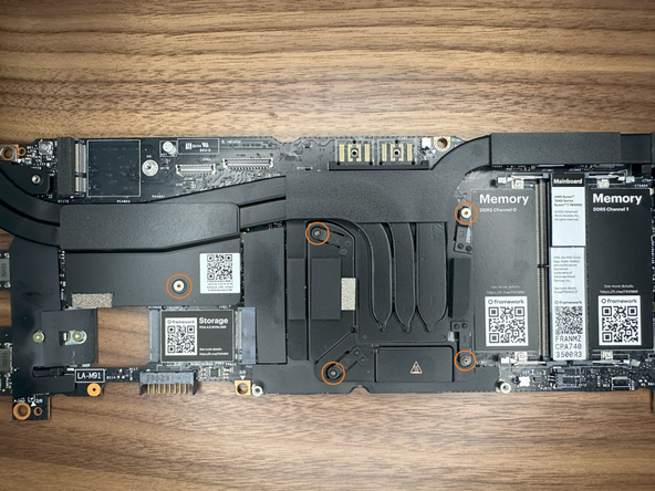
Using the Torx T5 bit in the Framework Screwdriver remove the six fasteners shown.
-
Note that one of the fasteners is under the Interposer Door.
-
-
-
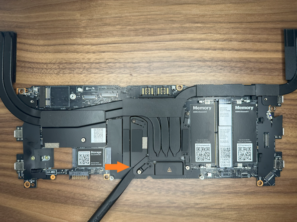
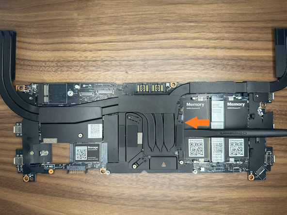
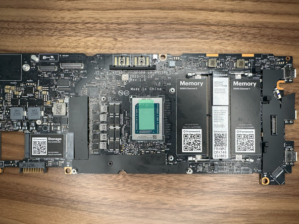
Lifting from the edges of the board and heatpipes as shown lift the Mainboard out of the Bottom Cover as shown.
-
There should be little resistance so if the Mainboard feels stuck, make sure all six fasteners were removed in the previous step.
and a warning that the screen now weighs more than the empty chassis, and will tip backwards over if not supported.
Christopher Ryba - Open Reply
There should be a step to remove RTC battery (if one is installed).
Josip Medved - Resolved on Release Reply
-
-
-
Unscrew CPU Heatsink screws in order as labeled 1-4.
-
These screws are captive so you do not need to worry about losing them.
-
Unscrew the 5th screw to the left of the CPU Heatsink on the metal plate.
-
-
-
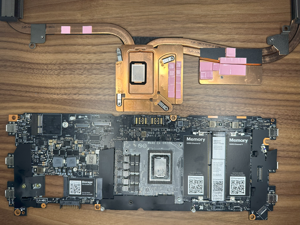
Using the spudger side of the Framework screwdriver, pry the CPU Heatsink away from the mainboard.
-
Work around the sides slowly prying it away.
-
Make sure in this process you do not bend one of the Heatsink pipes when using force.
I was able to easily remove the heatsink with minimal pressure by doing the following: 1. Before starting, laying laptop upside so that the heatsink is beneath the CPU. Running Cinebench for 10 minutes in that position. Turning off the PC in that position and allowing the laptop to cool to room temperature while maintain that position. I saw this worked for someone else so I gave it a shot and it worked great for me. 2. Pry with two spudgers at the same time in the positions indicated. I was able to pop it off without too much force in less than a minute using the above. Working at the edge of a table can help to get a good angle on the left side spudger.
Steele Trotter - Open Reply
I found this was the most difficult part. I did try like others and attempted to use a hair drier with no luck.
I eventually used a 3d printer heatbed set to 70C and left it there for a while (I don't remember exactly how long). That helped, though it still took more force than I liked to be able to remove it (laptop still runs fine).
Also, do not use the spudger on the left side of the heatsink since you will end up hitting the pink thermal pads (these are visible in the last image). Approaching it from the sides framework shown is all that should be needed (I was prying at non recommended locations out of frustration)
It is a good idea to remove the motherboard. Otherwise, you may lose track of things because the side coolers (especially the right one) can get stuck in the case.
The tip about using a hair dryer is very good (Novakov). This means you don't need to heat up the CPU by software-tools.
When installing the motherboard, pay attention to the right side of the cooler again. The cooler must be positioned as low as it is on the left side. Use very little force to help separate the coolers slightly so that they fit.
Michael Graf - Open Reply
I powered on and used my computer for a bit before attempting to remove the heatsink. It helped and I only needed a bit of force with my spudger to remove the heatsink. Just like changing the oil on a car.
Matthew Sanabria - Open Reply
As mentioned in https://community.frame.work/t/guide-liq... removing heat sinking might not be so easy as Liquid Metal is in solid form effectively soldering heat sink to CPU. You can use hair dryer or heat gun to gently increase temperature of heat sink and melt liquid metal. With that heat sink will come off easier.
-
-
-
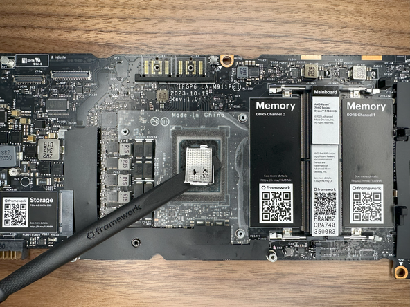
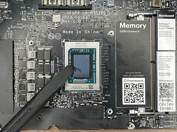
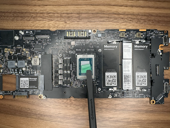
Using the spudger, remove the liquid metal from the CPU die.
-
Once mostly removed use Isopropyl Alcohol to clean the CPU die further and remove any remaining bits of the Liquid Metal.
-
Verify all parts of the Liquid Metal are removed, make sure the CPU die is clean and reflective.
-
Make sure there are no remaining parts of Liquid Metal in the system. If parts remain in incorrect spots, it can cause a short in the system.
Please be sure to use 99% isopropyl alcohol, or as pure as you can get it. use a q-tip, cotton ball, or a microfibre or lint-free cloth, apply the isopropyl alcohol to your cleaning tool of choice, and gently clean the CPU until it matches what the guide says later. Allow the alcohol to dry, wipe clean with a dry cloth, q-tip, etc., use an anti-static brush if you have one to clean off any debris, and when you restart your system, allow time for the thermal pad to burn-in, dont rev it up with cinebench or anything for a while after installation.
-lower purities like 70% can be risky to use on your CPU because of potential contaminants or impurities that can be left behind after the IPA evaporates.
-you should allow time for the PTM7958 to get used to the CPU, for it to go through a few cycles, then you can run some benchmarks. use a tool like HWinfo64 or your linux equivalent to check CPU temperatures and power usage
-
-
-
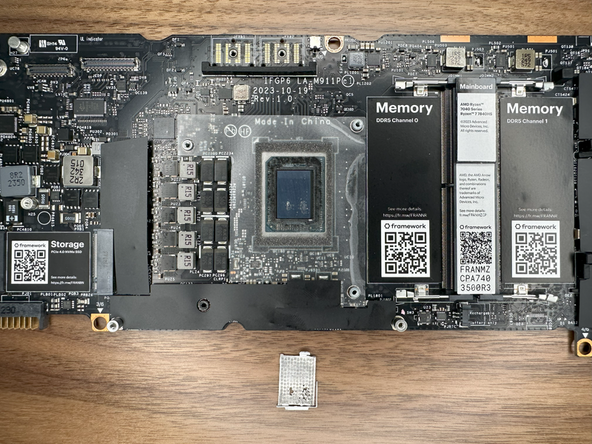
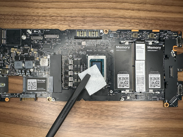
Gently peel away the clear protective tape surrounding the CPU.
-
Remove the black Sponge surrounding the CPU Die.
-
Do a final wipe down with Isopropyl Alcohol to remove any remaining bits of Liquid Metal, Sponge, or Residue.
-
-
-
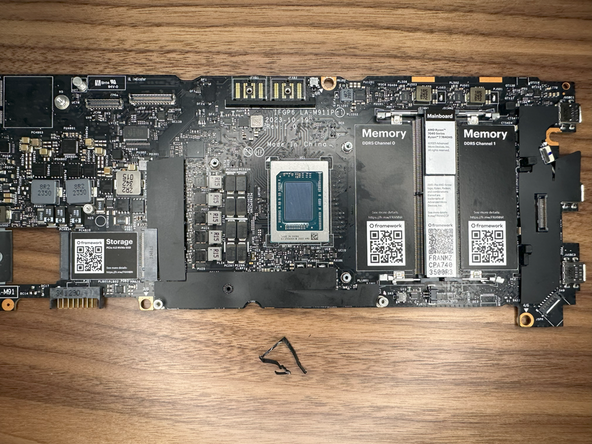
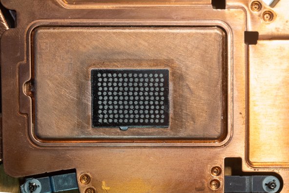
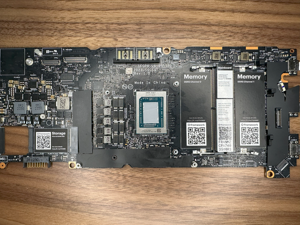
Make sure that your CPU Die and mainboard look like this with the Liquid Metal and Black Sponge removed.
-
-
-
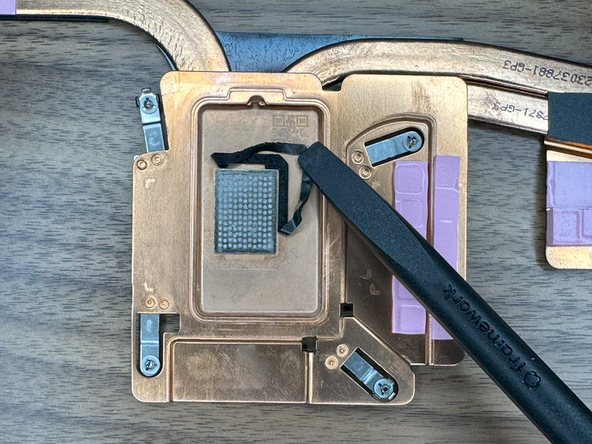
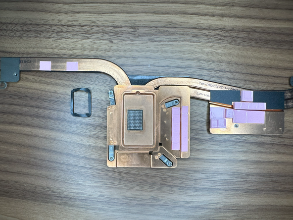
Using the Spudger of the Framework Screwdriver, remove the sponge on the Heatsink.
-
Using the Isopropyl Alcohol, clean off the sponge residue and wipe down the silver honeycomb textured plate.
Update this step to mention that the rectangle metal piece is meant to stay on the copper heatsink. I was wondering whether I needed to remove it at first but it appears soldered so it's not going anywhere. Perhaps a final image of what the heatsink must look like before re-installation would be good.
Matthew Sanabria - Open Reply
-
-
-
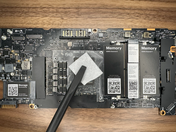
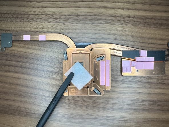
Gently remove the Clear backing on the PTM and apply it to the CPU die.
-
The PTM may be bigger than the CPU die and this is okay. Make sure the PTM is centered and has equal overhang on all sides.
-
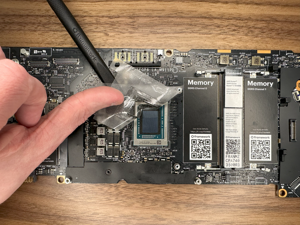
With the PTM on the CPU die, gently press against the Green backing; making sure it is applied successfully.
-
Gently and slowly remove the Green backing from the PTM.
-
PTM should now be successfully applied to the CPU!
-
-
-
Align the CPU Heatsink with the screw standoffs on the Mainboard. Slowly lower it until the Heatsink it touching the Mainboard.
-
Following the numbered order of the screws on the Heatsink, give each 2 turns.
-
Doing this ensures each is tightened with equal pressure and level on the CPU die.
-
Keep following this until all 4 screws are securely tightened.
-
-
-
On the metal plate to the left of the CPU, tighten this screw down.
-
-
-
Male sure that all cables (Speaker, WiFi, eDP, Webcam) are out of the way before installing the Mainboard.
-
Holding the Mainboard from the edges of the board and the heatpipes as shown, lower it into the Bottom Cover.
-
-
-
Using the Torx T5 bit in the Framework Screwdriver install the six Mainboard fasteners, noting that one of them is under the Interposer Door.
-
-
-
Starting from left to right install the WiFi Module, the Webcam cable and the eDP cable.
-
Plug in the WiFi Module, route the antenna cables through the channel above the Mainboard and around the metal post on the Mainboard as shown, and then secure the WiFi Bracket using the Torx T5 bit on your Framework Screwdriver.
-
Connect the eDP and Webcam cables by lining them up with the socket on the Mainboard and pushing gently down.
There's a problem with you WiFi card instructions.
When removing it from the old mainboard, there is no instruction to discard the plasic cover.
The new mainboard has it's own white plasic cover.
After wondering why I couldn't re install the WiFi and examining the fuzzy (when shown full screen) video above, I noticed that my problem is that I now have 2 white plastic WiFi covers and I have to discard the old one in order to install it on the new mainboard.
Someone might want to point that out so that others don't end up where I was.
(also higher res videos would be a big help)
-
-
-
Place the Ventilation Plate into place as shown, the holes for fasteners will align with the bottom cover.
-
Gently press down the Finger Print Reader cable to stick it to the Bottom Cover.
Also remember to flip up the retaining tab on the new motherboard, or you won't be able to insert the fingerprint reader cable
Neal Tibrewala - Open Reply
In my case, the adhesive is entirely on the old cable, or rather what is left on the bottom case is not sufficient to keep the cable to stick.
Ádám Juhász - Open Reply
The holes on the ventilation plate should line up with the holes on the motherboard which should line up with the hold underneath the mainboard. Otherwise, when it is time to install the midplate, the screw will not engage with the threads underneath.
Jeff H Silverman - Resolved on Release Reply
-
-
-
With the latch on the Mainboard open, connect the Fingerprint Reader cable to the Mainboard as shown.
-
This is quite a small connector so you may find it easiest to use the tab on the cable to push the cable into place.
-
Once fully inserted, close the latch on the Mainboard to secure the cable in place.
I find it difficult to connect the cable straight while it is sticking to the chassis, so I connect it first, and then stick it to the adhesive, but then the cable will no longer be flush with the bottom chassis, like it was shown in the previous step.
Ádám Juhász - Open Reply
I wish I has read that before I started. I think I have damaged the cable (I am sending a picture to support) and the machine will not power on.
Jeff H Silverman - Resolved on Release Reply
I found this to be impossible, given my hands and eyesight. My solution was to detach the cable from the vent plate. and install the cable on the mainboard before installing the mainboard in the chassis. (so before step 27). This allowed me to connection the reader cable with out having to navigate the bend, and the plastic cover.
Vincent Hanchon - Resolved on Release Reply
-
-
-
Connect the Speaker cable to the socket on the Mainboard by lining it up to the socket and pressing directly downward as shown.
I found this to be impossible, given my hands and eyesight. My solution was to detach the cable from the vent plate. and install the cable on the mainboard before installing the mainboard in the chassis. (so before step 27). This allowed me to make the connection to the reader cable with out having to navigate the bend, and the plastic cover.
Vincent Hanchon - Resolved on Release Reply
-
-
-
Depending on if you have the Expansion Bay Shell or Graphics Module, you will have to install it first. Follow the guide below to install the specific module you have. Once installed, come back to this guide and continue to the next step.
-
To install the "Expansion Bay Shell" from your Framework 16, please follow this guide: Install Expansion Bay Shell
-
To install the "Graphics Module" from your Framework 16, please follow this guide: Install Graphics Module (dGPU)
-
-
-
Lower the Battery into place, first aligning the bottom of Battery in the bottom cover as shown, then push down gently to attach the connector to the Mainboard.
-
Tighten the 3 captive fasteners to hold the Battery in place.
-
-
-
Place the Mid Plate onto the system, aligning the holes in the Mid Plate with the two guide posts.
-
These posts are on the left side and the right side, immediately above the speakers on both sides.
-
Take extra time to make sure it's sitting level/ flush.
I didn't notice the thermal pad until it started 'leaking' into one of the expansion ports. It had migrated down its channel in the mid plate because I store my laptop left side down in my backpack...
Andrew Pegram - Open Reply
Before this step there should be a note to reinstall RTC battery (if one was there before).
Josip Medved - Resolved on Release Reply
Note there is a thermal pad for the SSD on the bottom of the mid-plate. Mine had a blue plastic film still in place that needed to be removed before re-installing the mid-plate.
Matthew Cross - Resolved on Release Reply
I also failed to remove the blue film from the thermal pad for the primary SSD. A subsequent removal of the mid plate pulled the thermal pad away from the mid plate which is when I noticed it.
Same for me, had to remove the blue plastic from the bottom of the midplate as well as below the secondary ssd
-
-
-
Using the pull tab, gently press the Mid Plate connector down to connect it to the Mainboard.
-
Carefully align, then firmly press in the mid plate connector cable.
FYI. After using the computer for a while, this connection can start to loosen. This causes the trackpad and keyboard to randomly disconnect. If it gets bad enough that the computer no longer detects either during boot, you will be prompted to reseat this connection.
Dean Murry - Open Reply
Connection doesn’t give much feedback, it just kind of mushes itself in. It’s best to press in the middle of the orange strip and the pull tab, first near the bottom then near the top. Give a light tug on the pull tab to see if you encounter any resistance. If you do, it’s in!
It's tricky to tell if I've done this correctly. It seems to be firmly in place however, even though there's a plastic bit (not the tab) that still rocks around.
Bernie Maier - Resolved on Release Reply
-
-
-
Using the T5 bit in the Framework Screwdriver tighten the Mid Plate fasteners.
-
Before gently tightening the screws, double check that the mid plate is aligned correctly as shown in previous step.
-
These fasteners are labelled 2-17 (since the Mid Plate cable is number 1) and should be tightened in order, starting with 2 and ending with 17.
-
Do not overtighten these fasteners, and we recommend against the use of powered tools for these or any other fasteners on the Framework Laptop 16.
Instructions to secure the midplate cable are missing
hgrutter@lift-it.nl - Resolved on Release Reply
The deck should lay flat. Pay attention to any bulges at this point, which can be caused by thicker heatsinks attached to your SSD or RAM module.
Chaim Halbert - Resolved on Release Reply
-
-
-
Next install, two Spacer Modules, an LED Matrix, a Numpad, an RGB Macropad, or whichever other combination of two Small or one Medium sized Input Module you have.
-
Slide these in at an angle and lower into place, the same way the Keyboard was installed.
-
Whichever Input modules you chose to install, you should have no empty spaces in the top row before proceeding to the next step.
-
-
-
Please see our guide here on possible Input Module configurations.
-
Holding from the pull tabs at the bottom of the Keyboard module, line it up with the dashed guide lines printed on the Mid Plate. Note that you can align a Keyboard so that it is either along the left edge, the right edge, or centered. With the Keyboard held at a 20 degree angle, slide it up into place.
-
The notches along the top of the Keyboard will fit into the corresponding alignment guides under the Ventilation Plate.
-
Lower the Keyboard gently into place, it should snap in place magnetically and sit flat.
-
Ensure that the pins in the Mid Plate to the left and right of the Input Module Connector align into the corresponding holes in the Keyboard module.
-
-
-
Place the Touchpad Module flat, slightly below the Keyboard as shown.
-
Like the Keyboard, you can confirm it is properly aligned by lining it up to the dashed lines on the Mid Plate.
-
Applying gentle downward pressure to keep the Touchpad module flat, slide it up into place.
-
Remember that the Input Deck Latches should still be open at this point, otherwise the Touchpad Module won't slide on.
-
The Touchpad Module can be installed either directly below the Keyboard or offset by one space to the right. For example, the Keyboard can have the Touchpad below it, or the Keyboard can be left-aligned while the Touchpad is centered.
I had to gently push down the keyboard module for the touchpad to correctly slide up to meet it.
Will Stott - Open Reply
I had issues getting the touchpad module to slide all the way up so it was flush with it's spacers. What I figured out was gently place your hands flat on each side and give even downward pressure while sliding the touchpad module latterly up to the keyboard and this got it flush with the touchpad spacers.
Dan Wehner - Resolved on Release Reply
I am experiencing a significant edge between the touchpad module and spacers. I realize the touchpad should be sitting above the keyboard, but the upper corners of the touchpad module sit sharp up above the spacers. Has anyone experienced this? Any solutions to get the plates to sit flush?
I tried removing the keyboard, and the upper corners of the touchpad module sit slightly lower, but still are not flush with the spacers.
I think so. Happens with the Touch Modules Spacers too. A bit unsatisfying, but I can live with it.
Matias Fernandez - Resolved on Release Reply
I tried to get "Keyboard... left-aligned while the Touchpad .. centered.” (with numpad on right) but this wouldn't work. I also didn't read the "The Touchpad Module can be installed either directly below the Keyboard..." note too clearly... I think it should have a warning similar to the fasteners. I went down a rabbit hole of troubleshooting. I used Possible Input Module combinations on Framework Laptop 16 and later My touchpad isn't working because I inadvertently triggered a device issue during my troubleshooting requiring the "disable/enable the touchpad in Device Manager" process.
Trevor Textor - Resolved on Release Reply
@crippledlord Same here. I tried multiple times to get the touchpad module flush but it always ends up just a tad above the keyboard. Everything else is flush. Could be better but not something hinders the use.
I think the same goes to the right. I wanted the keys modules to the left and track all the way to the right. I can only get one space over.
Raju Rayavarapu - Resolved on Release Reply
It appears that the trackpad module can not be mounted any further left than the keyboard. i.e I wanted the keyboard all the way to the right and the num pad all the way to the left, but the track pad won't fit anywhere other than directly below the keyboard module.
Jonathan P Cox - Resolved on Release Reply
Should the edge of the edge of the touchpad module stick above the keyboard slightly? It's not sharp, but is noticable.
Tonyromo1988 - Resolved on Release Reply
@crippledlord I think so. Happens with the Touch Modules Spacers too. A bit unsatisfying, but I can live with it.
-
-
-
Just like installing the Touchpad module, place the Touchpad Spacers flat on the Input Deck, slightly below the Keyboard or Spacers above.
-
Applying gentle pressure, slide the Touch Module Spacers into place.
-
With the Touchpad Module Spacers installed there should now be no empty spaces on the Input Deck.
The touchpad CAN be placed and work in other positions beside the middle, you can place it on the left or even on the right if you have the keyboard centered, you can see all the possible combinations here Possible Input Module combinations on Framework Laptop 16
unfortunately the touchpad only fits in the middle.
The transitions from touchpad to spacers are clearly visible and tactile edges.
you can press both touchpad module and spacers. Doesn't feel firm.
I miss an overlap between spacers and touchpad to accommodate this
Marout Yasuo Sluijter-Borms - Open Reply
Unfortunately, my spacers on the right and left of the touchpad are floating a bit. There is so much play that the touchpad has a noticeable edge, meaning the spacer and touchpad are not flush. I have gently tightened all of the screws underneath. Any idea how to fix this?
I am experiencing a significant edge between the touchpad module and spacers. I realize the touchpad should be sitting above the keyboard, but the upper corners of the touchpad module sit sharp up above the spacers. Has anyone experienced this? Any solutions to get the plates to sit flush?
I tried removing the keyboard, and the upper corners of the touchpad module sit slightly lower, but still are not flush with the spacers.
If the spacers don't seem to fit properly, check that you've tightened the underlying Mid Plate screws enough, particularly numbers 16 and 17.
George Pearson - Resolved on Release Reply
-
-
-
Once all Input Modules are installed, close both Input Deck Latches to secure them in place.
It might be worth mentioning, when installing the M2 SSD, if you didn't have one installed, you need to remove the blue film GENTLY! Underneath the blue film is a pasty gray matter which I accidentally scrapped up a bit. I was peeling the blue film off really gently too, from what I had read and still, I f**ked it up!
Mike Laurel - Resolved on Release Reply
don't forget to replace the expansion cards :) (Step 4)
Leopold von Seckendorff - Resolved on Release Reply
At this point or earlier, if you have both a graphics card and expansion bay in your order you might wonder what the L shaped extra part is and where it goes. My graphics module came installed and there was an L shaped interposer left in the box (labeled FRAKHNC PA1403200JM). That part is only used if you swap out the graphics card for the expansion bay, it's not needed if your graphics module is pre-installed.
-

Cancel: I did not complete this guide.
10 other people completed this guide.
7 Comments
Just followed this guide successfully. As others have mentioned, it is missing steps for removing the midplate and the battery.
Steele Trotter - Open Reply
Great guide. it is missing the "remove midplate" step, otherwise very complete. I followed all the instructions and now my framework 16 runs like brand new again.
I would also like to see maybe a video demonstration for step 17 just so its easier for people who are doing this the first time.

The guide is still missing the midplate removal step (before step 9, I assume).
Battery disassembly and assembly mentioned in the other comments are already added.
My Framework 16 freq boost improved from 3700 to 4200 mhz under stress test after applying PTM while keeping the same core temp, 99.8C. Even my balanced profile is now at 3800 mhz under stress test, so even that one is better than stock on performance profile. Let's see how long it lasts! :)
Thanks guys for the awesome tutorial! I love it when products get this kind of attention to detail!
This Guide seems to be missing a step were the battery is removed. It has the step installing battery but not the removal of the battery
Yep, this guide is missing the "remove battery" step which is required to remove the main board. Just did the Liquid Metal to PTM7950 swap on my Framework 16.