
Introduction
Here it is, the Framework Keyboard replacement guide! Before you proceed with the keyboard replacement, here is a helpful tip: It is highly recommended that you store each screw in a dedicated space (such as a cup) as you are removing them. It is important to not mix up or lose any screws.
The keyboard is screwed into the Input Cover. The only tool you'll need is your Framework Screwdriver to completely remove the keyboard.
This is one of the few repairs that is time consuming on the Framework Laptop. A quicker but more expensive alternative is to replace the Input Cover which contains the keyboard instead.
Tools
Parts
-
-
Power off the Framework Laptop by navigating to the Windows icon on the bottom left and clicking on "Power" followed by "Shut down," or if on Linux, the equivalent action there.
-
-
-
Unplug your power cable from the USB-C Expansion Card in your Framework Laptop.
-
-
-
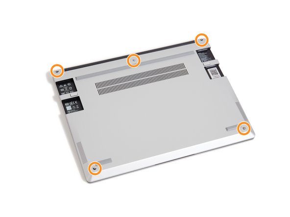
Close the lid on your Framework Laptop and place it upside down on a soft, non-marring surface, such as the bag that it shipped in.
-
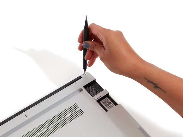
Using the T5 bit in the Framework Screwdriver, unscrew the 5 fasteners on the Bottom Cover. These fasteners will remain attached in the Bottom Cover so that you do not lose them.
-
The fastener on the bottom left (circled in red) will not unscrew as far as the others, as it is acting as a lifter for the Input Cover.
-
You'll hear this fastener start clicking as you rotate when it is unscrewed far enough.
-
Do not use a powered tool for these steps, as this will likely result in damage to the fasteners.
-
-
-
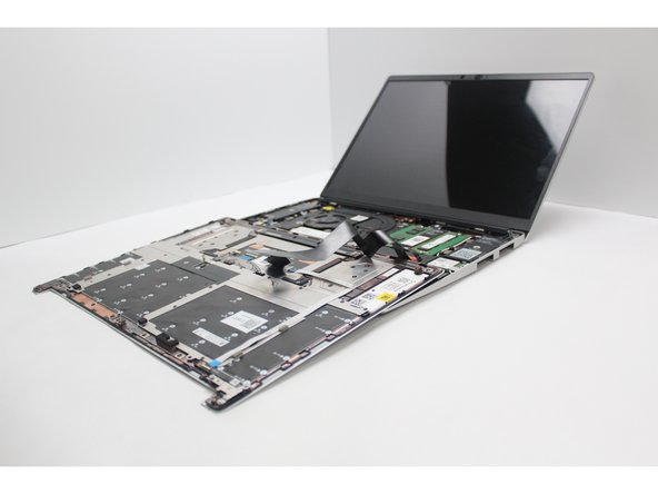
Flip the Framework Laptop back over and open the lid to around 120 degrees.
-
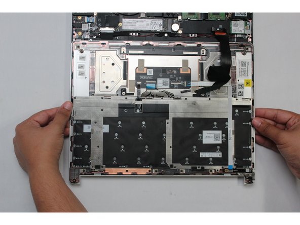
Important: Pull the Input Cover off carefully as it is still attached to the Mainboard via the Touchpad Cable. You don't need to disconnect this cable to do most repairs. You can just flip the Input Cover over. If you do want to disconnect it though, make sure to disconnect the Mainboard side using the finger loop over the orange label.
-
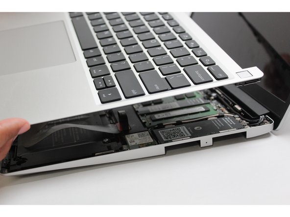
The bottom right corner of the Input Cover lifts up when the five fasteners are properly unscrewed from the previous step. You should not have to use any excessive force to remove the Input Cover.
-
Carefully lift the cover up from the bottom right corner. If you need to, you can use the spudger end of the Framework Screwdriver to lift it as well. Lift the Input Cover off the Mainboard, flip it over (keyboard side down), and place it about halfway on the Bottom Cover.
-
Be sure not to put too much force on the Touchpad Cable when doing this.
-
If the LEDs on the left and right sides of the system are flashing red when you lift off the cover, it means the system is still powered on. Make sure your power cable isn't plugged in and that you have shut down correctly.
-
Note that it may take up to 30 seconds after shutting down for the system to fully power off. Wait until the LEDs stop flashing before proceeding.
-
You should keep the Battery connector plugged in unless you need to replace the Battery, Mainboard, or Speakers. This connector is easy to accidentally damage, so it's better to not handle it.
-
-
-
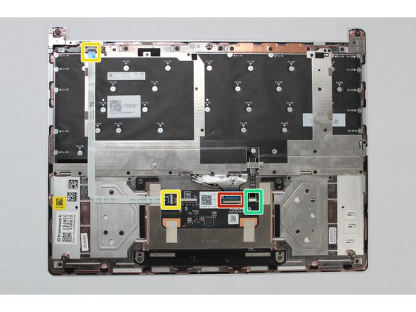
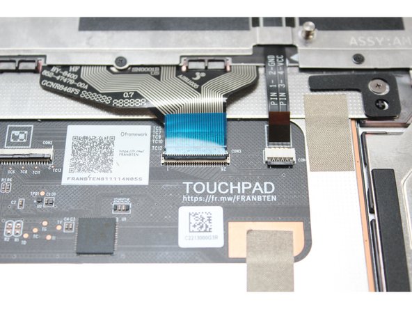
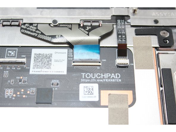
You will be disconnecting the following cables:
-
Fingerprint Cable (from both ends)
-
Keyboard Membrane
-
Keyboard Backlight
-
In this image, the Touchpad Cable is also removed, but we recommend keeping it attached, since there is likely adhesive holding it in place. You'll just need to hold that cable out of the way when accessing the fasteners that are near it.
-
-
-
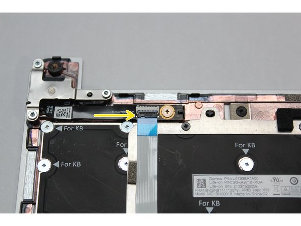
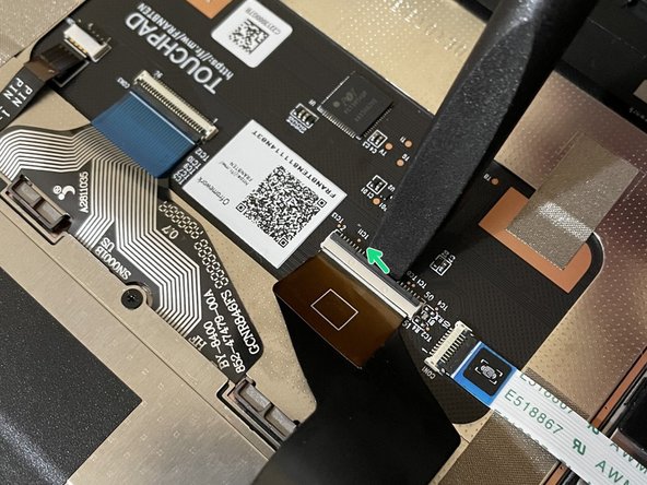
The Fingerprint Cable will be completely disconnected from both ends. Start by disconnecting it from the actual Fingerprint Module.
-
Lift the black latch up using your fingernail or spudger end of the Framework Screwdriver and pull the cable straight out.
-
-
-
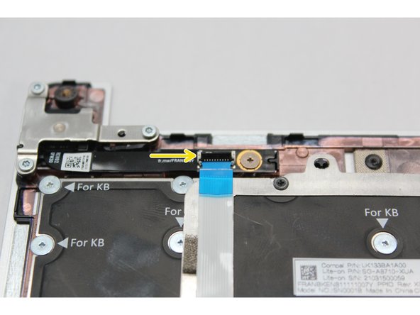
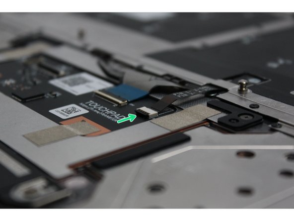
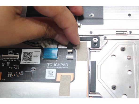
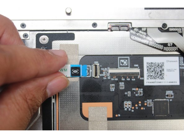
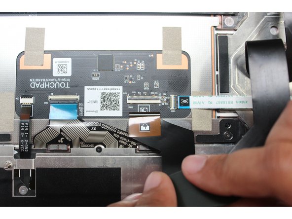
Next, disconnect the Fingerprint Cable from the Touchpad Module. Lift the black latch up using your fingernail or spudger end of the Framework Screwdriver and pull the cable straight out.
-
Use caution when lifting it up the Fingerprint Cable as there is some adhesive holding it to the bracket.
-
Remove the Fingerprint Cable away and keep it in a safe place as you'll need to connect it back when you install the replacement Keyboard.
-
-
-
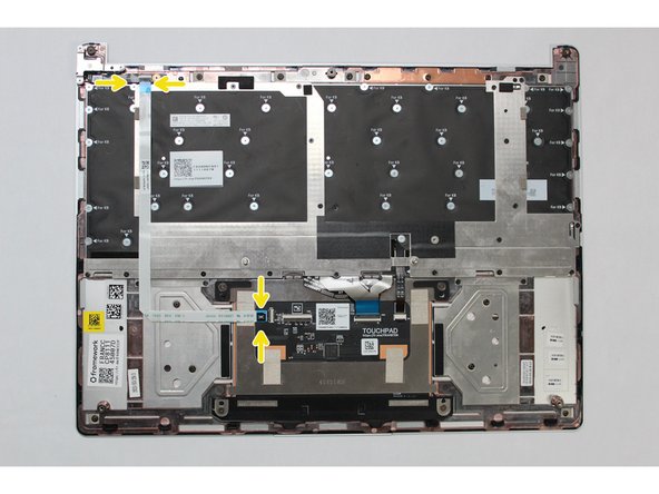
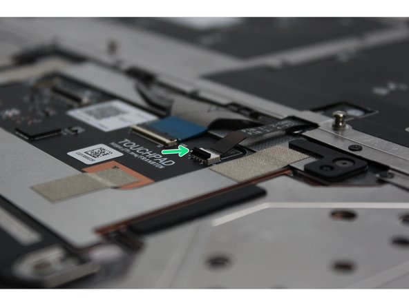
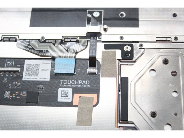
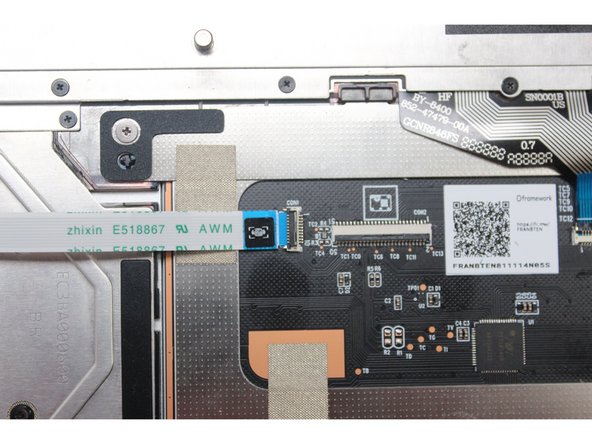
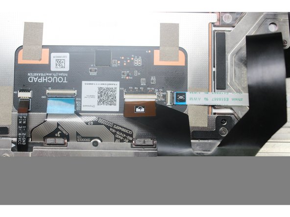
Using the spudger end of the Framework Screwdriver or your fingernail, disconnect the Keyboard Membrane from the Touchpad Module by switching the black latch up and sliding the cable straight out.
-
-
-
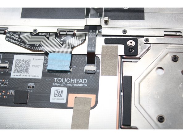
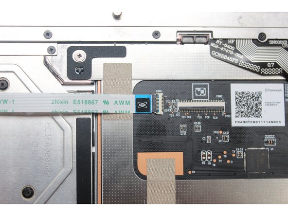
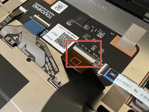
Using the spudger end of the Framework Screwdriver or your fingernail, disconnect the Keyboard Backlight cable from the Touchpad Module by switching the black latch up and sliding the cable straight out.
-
-
-
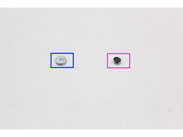
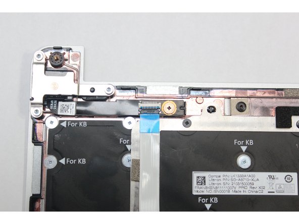
All the necessary cables are now disconnected but before proceeding with removing the fasteners it is important to know the difference between the two types of fasteners you are going to be working with.
-
The smaller black fasteners are to be used only on the silver bracket on top of the Keyboard.
-
The larger silver fasteners are used to hold the actual Keyboard in place. You should fasten these only where it reads "For KB."
-
Tip: It is very important to not mix up the two screws together - they are magnetic and very easy to lose. Find a dedicated space for each fastener type. Two small cups would be the best option.
-
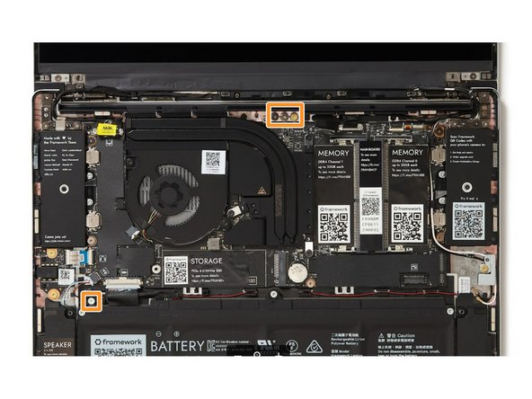
We've included a few spare fasteners that you'll be able to find right in the Bottom Cover as indicated in the second picture.
-
-
-
Using the PH0 bit in Framework Screwdriver, unscrew all black fasteners on the silver keyboard bracket.
-
Your Framework Screwdriver has a double-sided bit! One end is the T5 bit, the other end is the PH0 bit. To switch from the T5 bit to the PH0 bit, pull the bit out using your fingers, flip it around, and place it back into the screwdriver!
-
The fasteners are magnetic and very small. To avoid losing them gather them in a dedicated safe space (such as a cup) as you are removing them. Remember to not mix these fasteners with the "For KB" fasteners you are removing next.
-
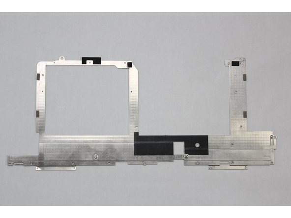
Lift the silver keyboard bracket away from the keyboard bracket.
-
-
-
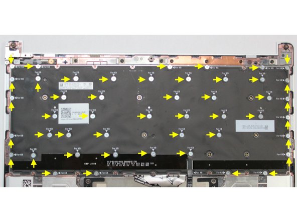
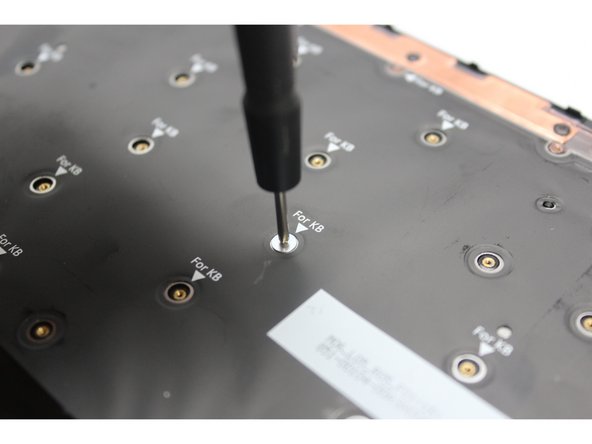
Using the PH0 bit in the Framework Screwdriver, unscrew all "For KB" fasteners holding the keyboard in place.
-
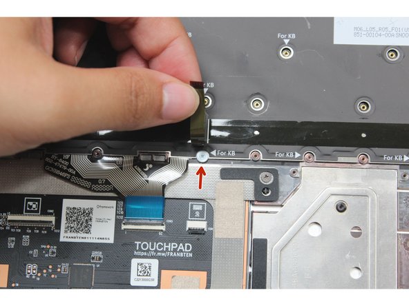
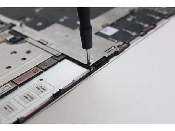
One of the fasteners is hidden under the Keyboard Backlight cable , it must be removed as well. Lift the cable up to expose the fastener and unscrew it. See the second image for more details.
-
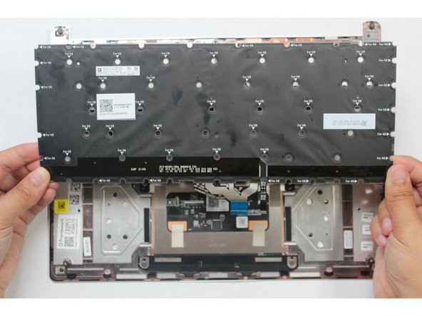
Once all screws are removed use the spudger end of the Framework Screwdriver or your fingernail to lift any corner of the keyboard off the Input Cover. The keyboard is now fully removed from the Input Cover.
-
-
-
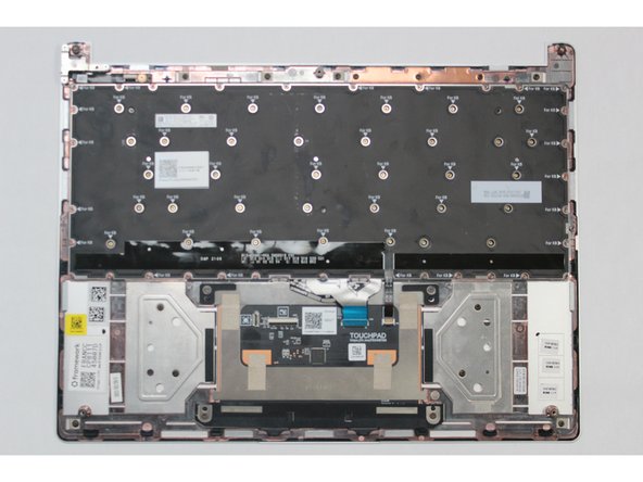
Gently place the new Keyboard into the Input Cover by aligning the edges of the keyboard with the Input Cover as indicated in the first image. The keys should be facing down.
-
Using the PH0 bit in the Framework Screwdriver, screw all the silver fasteners into the slots marked "For KB" that hold the keyboard in place.
-
Do not attempt to screw any fasteners into a slot that is not marked with "For KB."
-
Do not overtighten the fasteners. They are very small and don’t need much force. Only screw in until you feel some resistance.
-
-
-
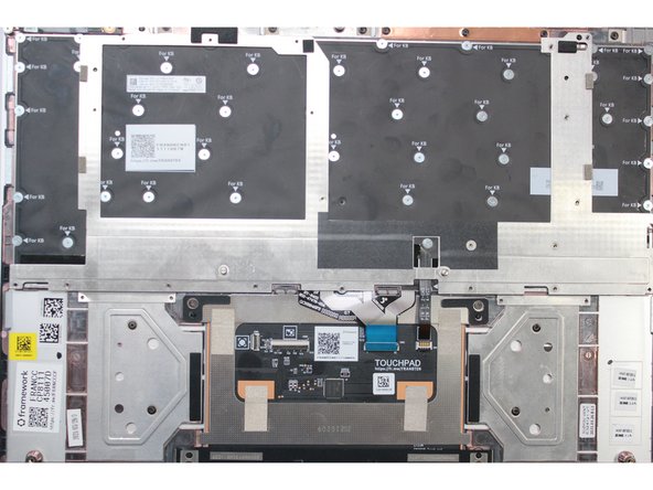
Once all the silver fasteners are in place on the Keyboard, find the silver bracket and place it over the keyboard by aligning it as indicated in the first image.
-
Screw all the black fasteners into place in the silver bracket.
-
Do not overtighten the fasteners. They are very small and don’t need much force. Only screw in until you feel some resistance.
-
-
-
Connect the Keyboard Backlight Cable into the Touchpad. Make sure the black latch is flipped up so that you can slide the cable into the connector.
-
Make sure to slide the cable in until the white line is almost at the edge of the connector.
-
Flip the black latch down to secure the cable.
-
-
-
Connect the Keyboard Membrane cable into the Touchpad. Make sure the black latch is flipped up so that you can slide the cable into the connector.
-
Slide the cable in until the white line is almost at the edge of the connector.
-
Flip the black latch down to secure the cable.
-
-
-
Connect the Fingerprint Cable into the Fingerprint Module. Make sure the black latch is flipped up so that you can slide the cable into the connector.
-
Slide the cable in until the white line is almost at the edge of the connector.
-
Flip the black latch down to secure the cable.
-
-
-
Connect the other end of the Fingerprint Cable into the Touchpad Module. Make sure the black latch is flipped up so that you can slide the cable into the connector.
-
Slide the cable in until the white line is almost at the edge of the connector.
-
Flip the black latch down to secure the cable.
-
-
-
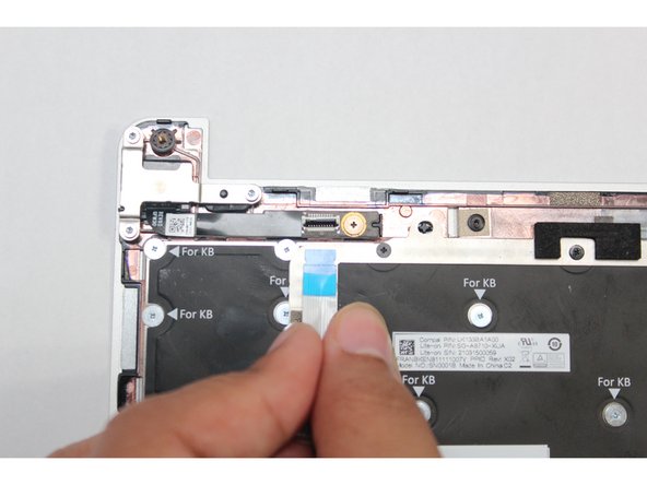
Place the Input Cover on the Bottom Cover Keyboard Side down as indicated in the first Image.
-
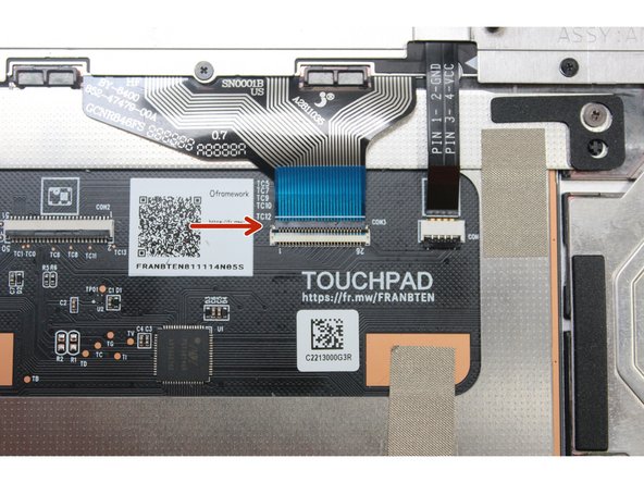
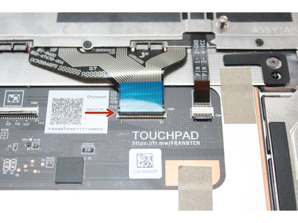
Connect the Touchpad Cable. Make sure the black latch is flipped up so that you can slide the cable into the connector.
-
Slide the cable in until the white line is almost at the edge of the connector.
-
Flip the black latch down to secure the cable.
-
-
-
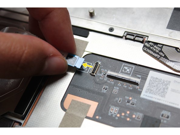
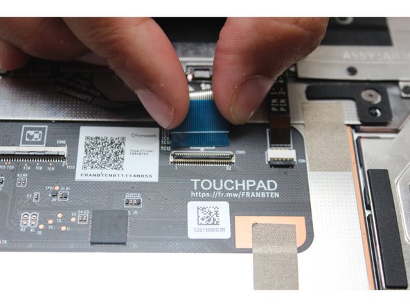
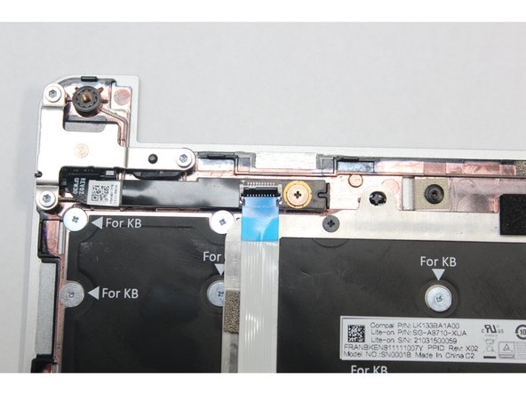
Before closing up the laptop, make sure that the Touchpad end of the Touchpad Cable is fully seated in the receptacle.
-
The cable should be inserted far enough that the white line almost touches the receptacle.
-
If it is not inserted far enough, you'll need to flip up the black latch on the other side of the connector, slide the cable in further, and then close the black latch again.
-
-
-
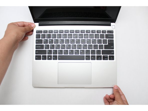
Flip the Input Cover over the Bottom Cover so that the keyboard is facing up and attach it to the Bottom Cover by aligning the top and bottom edges of both covers.
-
Tip: The covers are magnetic and should fit into one another easily. If you feel any resistance simply lift the Input Cover up and try again.
-
-
-
Close the Framework Laptop and turn it upside down to reveal the five fasteners on the Bottom Cover.
-
Using the T5 bit in the Framework Screwdriver, screw all 5 fasteners back into the Bottom Cover.
-
Be sure to not over-tighten the fasteners.
-


- To purchase a Framework Laptop visit the Framework website
- Want to learn more about the Framework Laptop? Take a look at our blog
- If you have any questions or concerns, feel free to reach out to Framework Support
- To purchase a Framework Laptop visit the Framework website
- Want to learn more about the Framework Laptop? Take a look at our blog
- If you have any questions or concerns, feel free to reach out to Framework Support
Cancel: I did not complete this guide.
36 other people completed this guide.
24 Comments
Is this the same for the framework 17? I'm confused by all these steps, since I thought the 17 just popped the keyboard out?
Dan Ginovker - Open Reply
I just performed this on a Ryzen AI 300. It was fairly straight forward. There was one screw that was stripped out from framework and it was on the outer most edge of the keyboard. I was able to slide the keyboard out and install the new one. I found out my Control keys no longer register (left or right) I double checked the connections 3 times and even ended up cleaning the connections with 99% isopropyl and still the Ctrl keys do not work. Not sure what to do from here.
Jason Mangano - Open Reply
Successfully performed on the Framework 13. Three of the silverhead screws were stripped, so I used a power drill to extract them. Currently using the laptop without the missing screws, both the keyboard and laptop are functioning perfectly.
On that note, I’d recommend Framework consider using stronger screws if possible. I’m pretty new to DIY, so I’m not sure how feasible that might be, but it could help avoid issues like this for beginners.
Ashfaque Ahbab - Open Reply
Did this over the course of about an hour, found out that the keyboard fastener underneath the backlight cable was partially stripped (of course it's the one right under an unremovable cable lol). Ended up having to remove the touchpad cable and put the input cover on a flat surface to get the right pressure to get the screw out. Go slow if you have to remove the touchpad cable, there's a good amount of adhesive under it that will release bit by bit with steady pressure.
aye used the gu-aye-d to replace the cuh-eyboard my laptop already had w/ a lat-eh-n amer-eh-can cuh-eyboard. comma. aye was able to swap them well and hadn´t seen any problems when aye was reasembl-eng the computor. However now that aye am actually test-eng eh-t out theres a couple cuh-eys {cuh-ees. the ones you press to type letters and stuff} that won´t reg-eh-ster no matter what aye do.
the cuh-eys {cuh-ees} that don´t funct-eh-on are:
8 , i k {the lower br-y-tness cuh-ee} ******or any of there sh-eh-ft or alt cuh-ey {cuh-ee} forms
anybody no any decent remedys for th-eh-s?
{no eh-ts not just me not be-eng used to the layout. aye have attempted eh-t w/ the cuh-eyboard sett-eng set to standard US just to see try and they also don´t wor-cuh} {also have fun read-eng th-ehs lol. and than-cuh you eh-ff you can help}
crystal clear - Open Reply