
Introduction
Congratulations on getting the Framework Laptop 16 DIY Edition! Follow this quick start guide to assemble your laptop and get it running.
Tools
Parts
No parts specified.
-
-
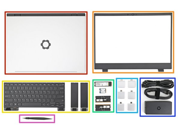
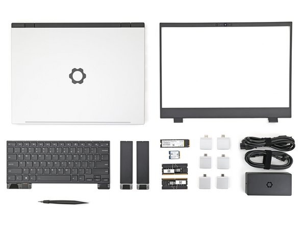
Unbox your Framework Laptop and make sure you've received the following items:
-
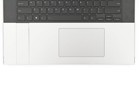
Framework Laptop chassis with pre-installed Mid Plate, Touchpad Module, and Touch Spacers.
-
Bezel
-
Keyboard and Input Modules
-
Memory and Storage
-
Expansion Cards
-
Power Adapter
-
Framework Screwdriver
-
-
-
Open the laptop
-
-
-
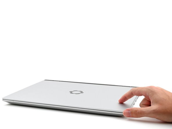
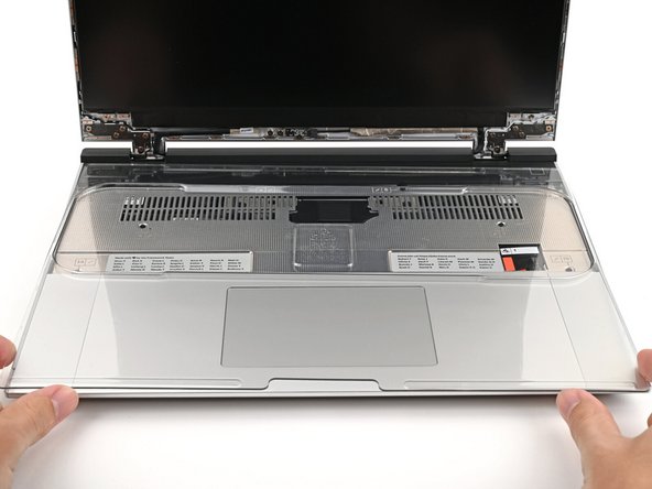
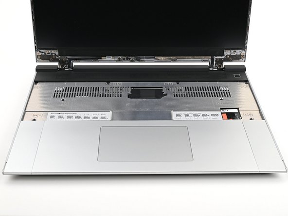
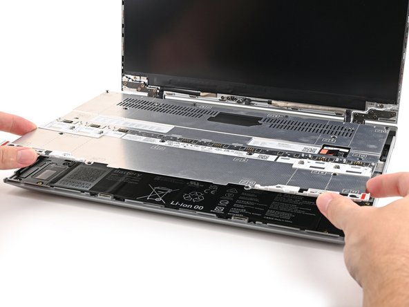
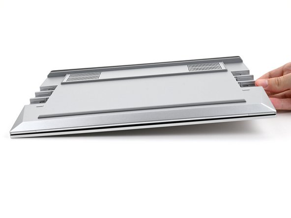
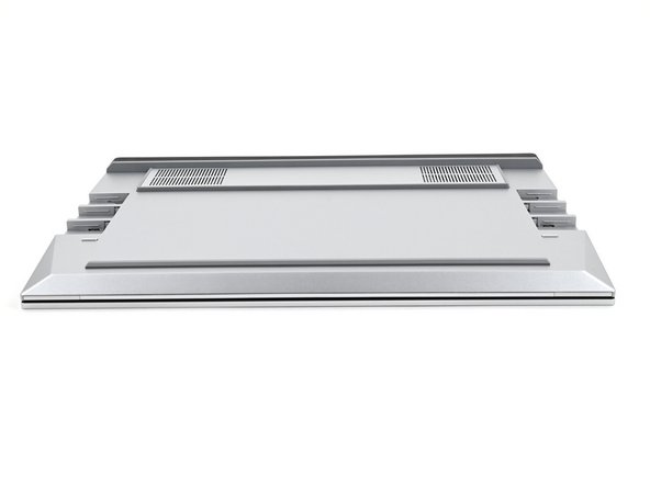
Remove the plastic cover.
-
The protective cover is made of post-consumer recycled PET and is highly recyclable. Please recycle this with your household recycling.
-
-
-
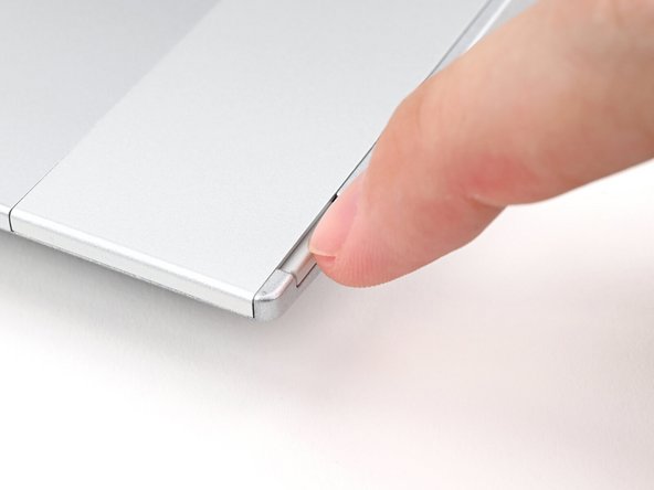
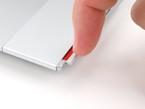
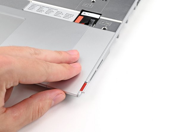
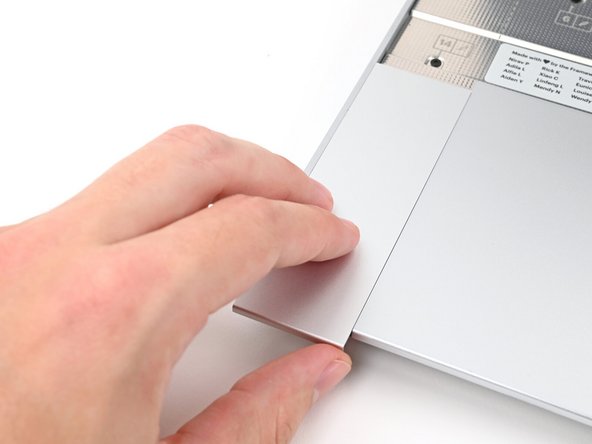
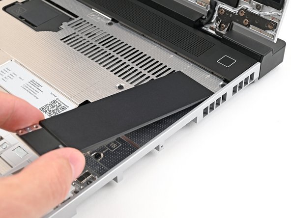
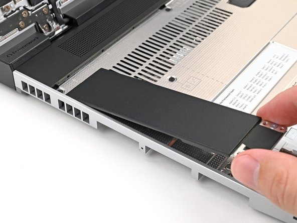
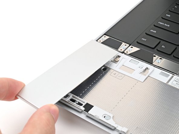
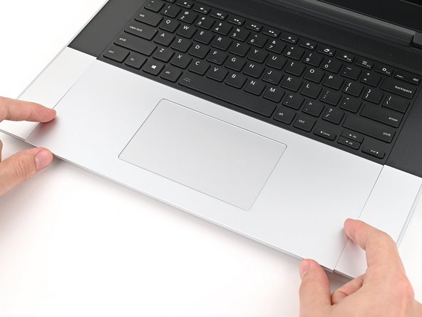
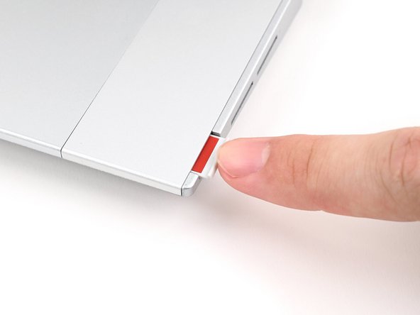
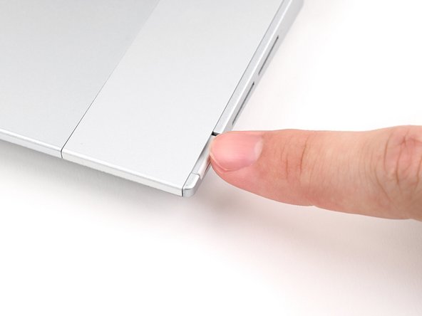
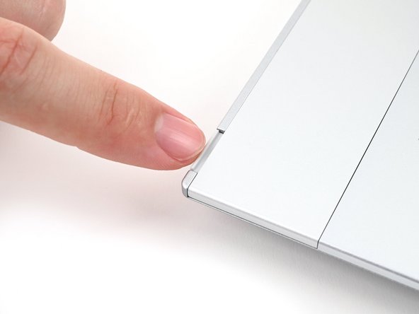
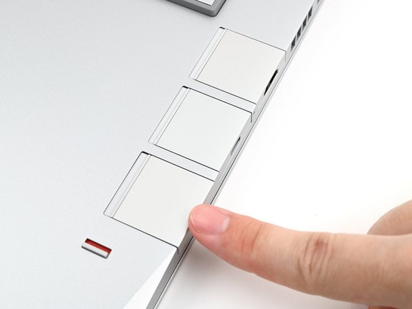
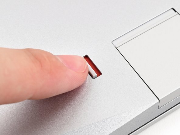
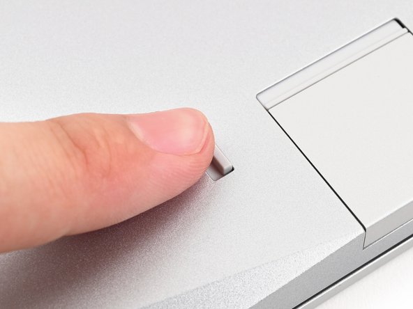
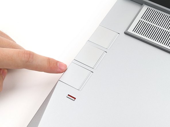
Use your fingernail to pull out the Input Module latch and unlock the Touchpad Spacer next to it.
-
-
-
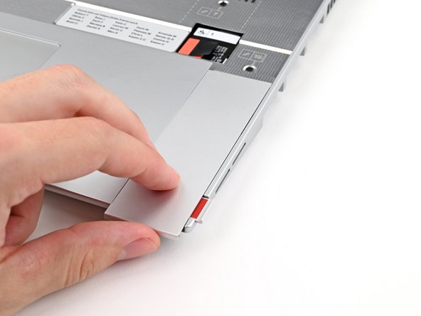
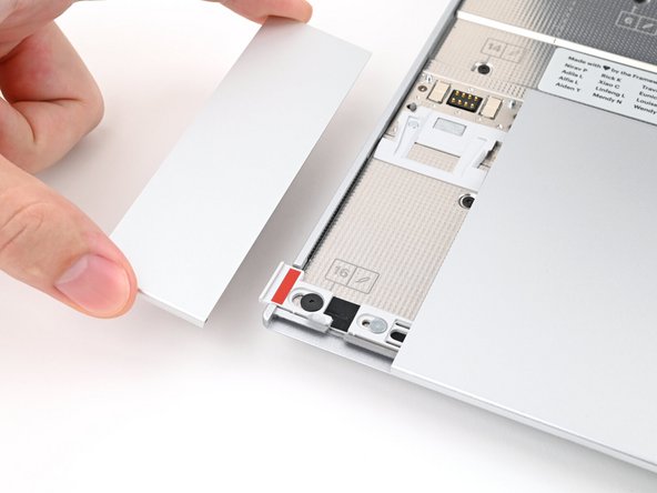
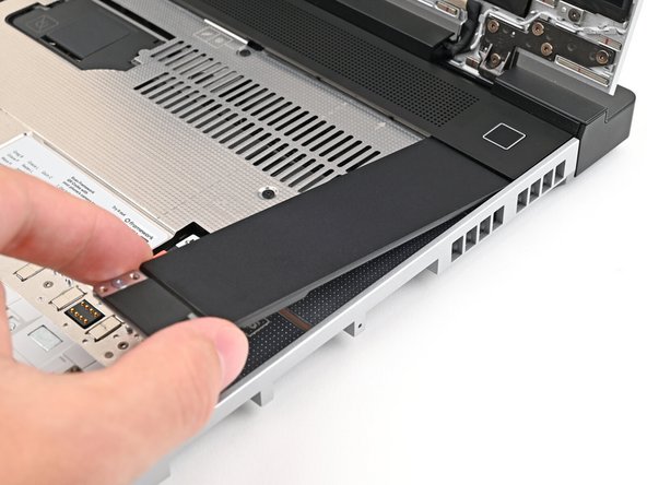
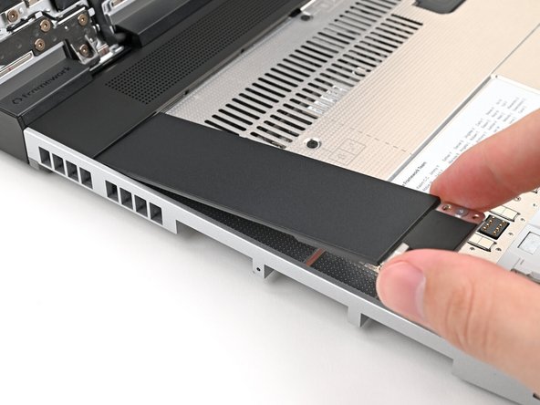
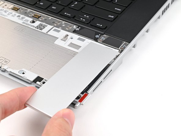
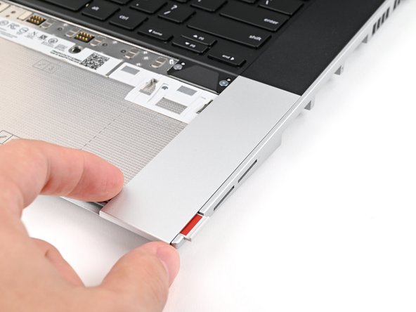
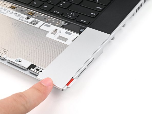
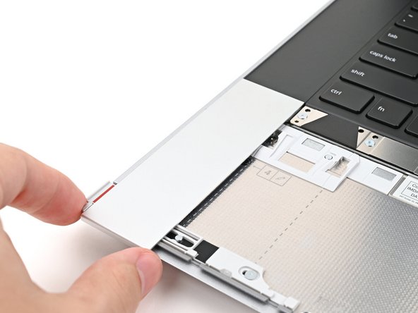
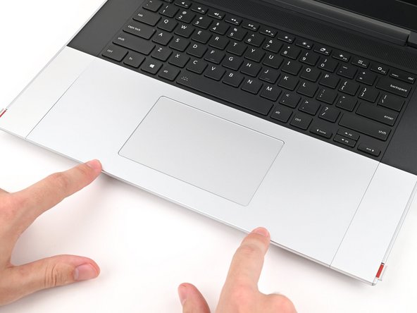
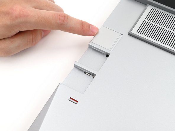
Use your fingers to slide the Touchpad Spacer toward the bottom edge of the laptop and unclip it.
-
If you're having trouble, check if the corresponding Input Module latch is properly unlocked.
-
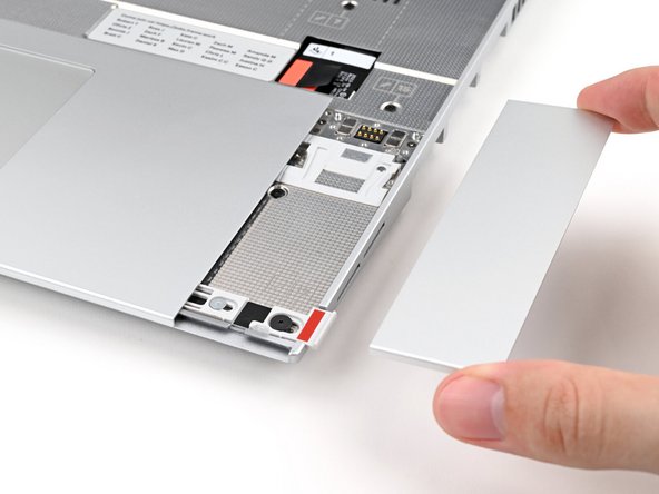
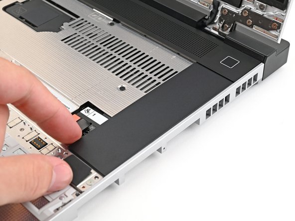
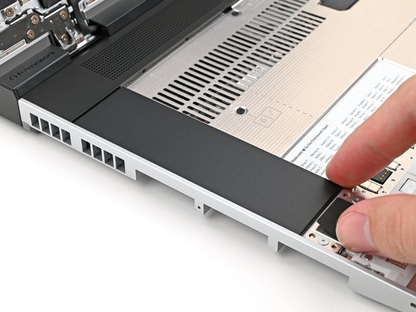
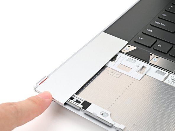
Lift the Touchpad Spacer off the laptop and remove it.
-
-
-
Repeat the previous two steps to remove the other Touchpad Spacer.
-
-
-
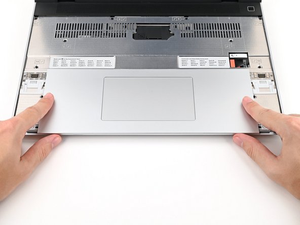
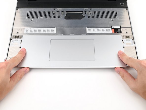
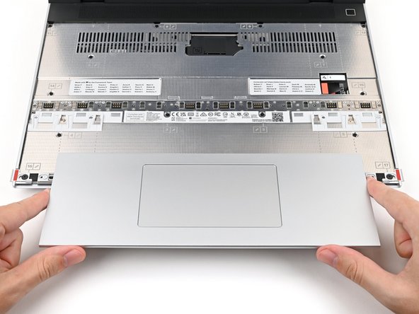
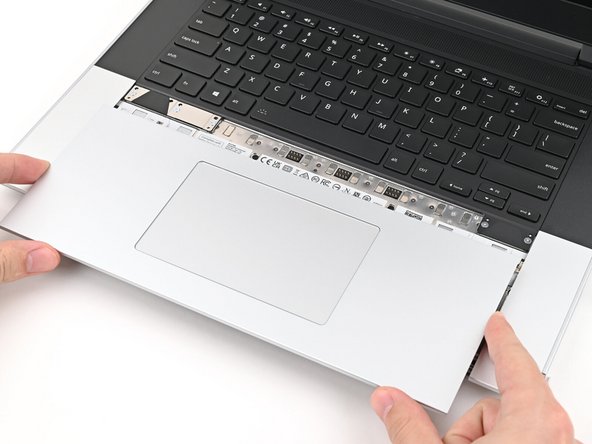
Use your fingers to slide the Touchpad Module toward the bottom edge of the laptop and disconnect it.
-
Lift the Touchpad Module and remove it.
-
-
-
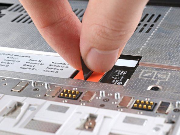
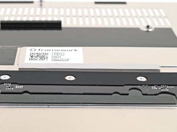
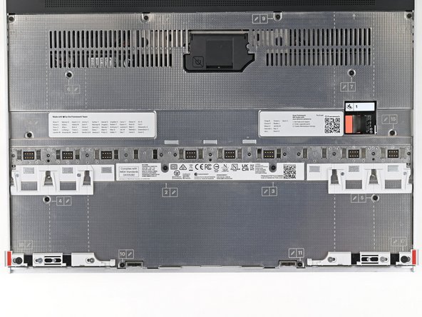
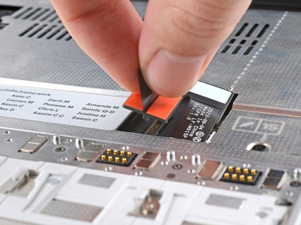
Grip the black pull tab on the Mid Plate cable press connector and lift up to disconnect it.
-
-
-
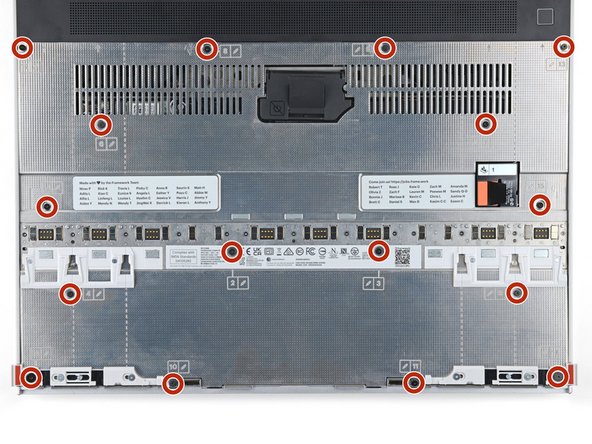
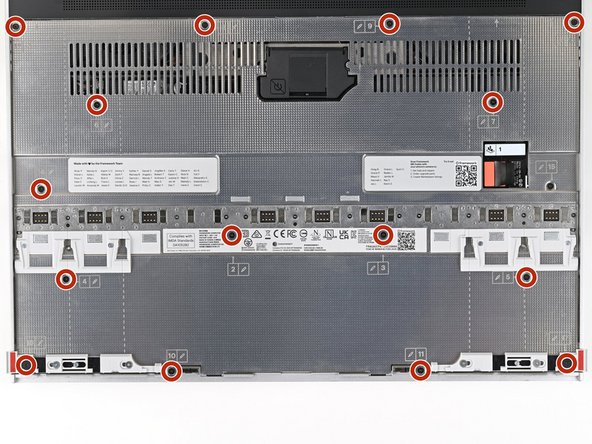
The Mid Plate screws are ordered from 2–17 (number 1 is the press connector). You don't have to follow the order, but you can use it to help keep track of the screws you've loosened.
-
Use your Framework Screwdriver to loosen the 16 captive T5 Torx screws securing the Mid Plate.
-
-
-
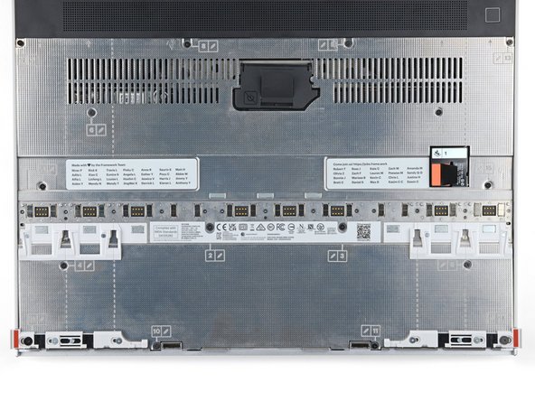
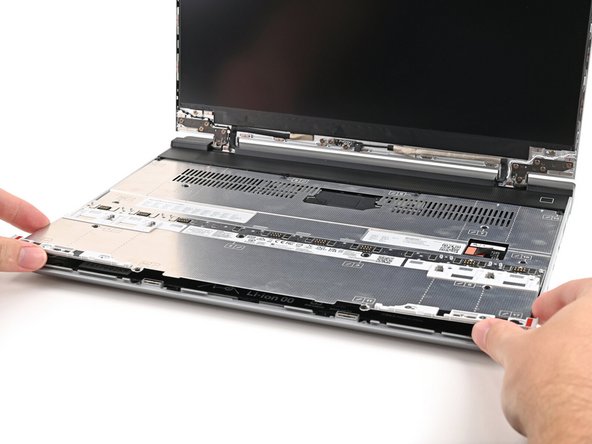
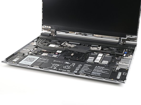
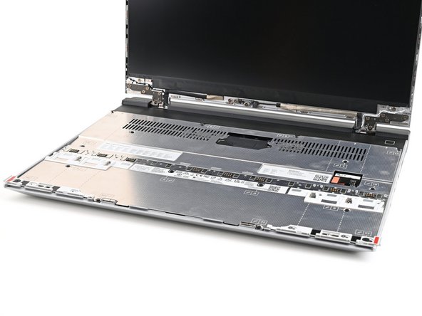
Use your fingers to lift the Mid Plate off the laptop and remove it.
-
-
-
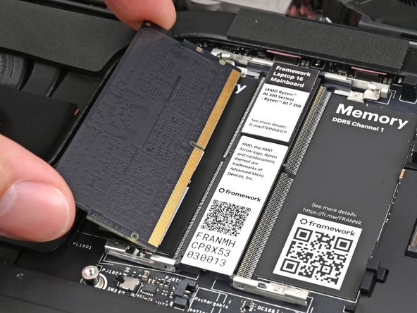
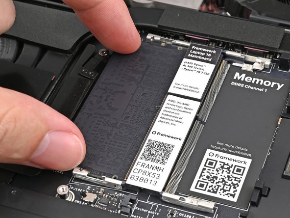
Hold the memory module by its edges. Don't touch the gold contacts with your fingers. If you do, wipe the contacts with a clean, lint-free cloth to remove any finger oils.
-
Orient the module with its label facing down and align the gold contacts with the left socket labeled DDR5 Channel 0.
-
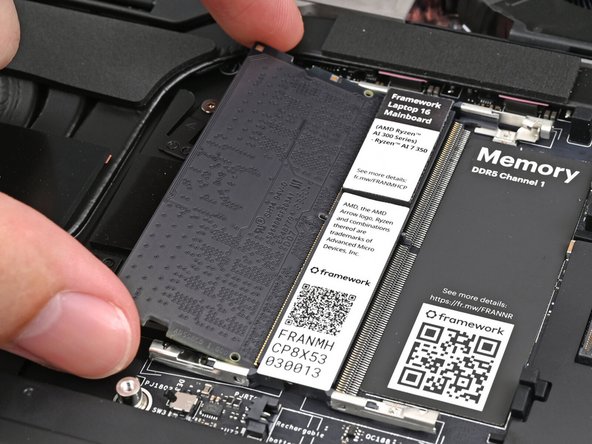
Insert the contact edge into the socket at a shallow angle. The gold contacts should mostly be covered by the socket.
-
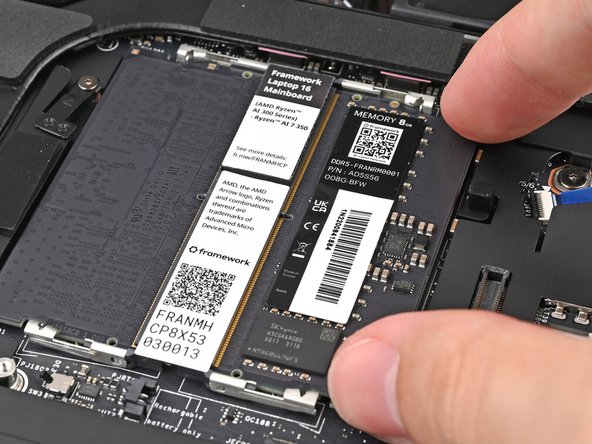
Press the edges of the memory module down until the side clips lock it in place.
-
-
-
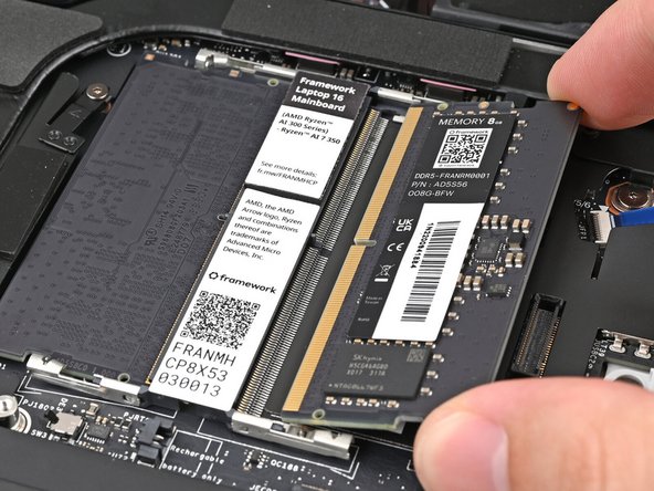
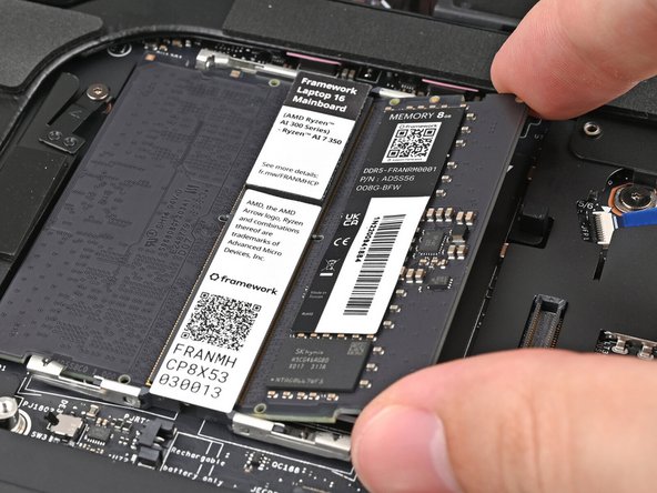
If you're using two memory modules, orient the other module so its label is facing upward and repeat the previous step for the other socket labeled DDR5 Channel 1.
-
-
-
If a Thermal Pad has fallen off over this section, please see our Knowledgebase page of where to re-attach it.
-
If you're installing a secondary SSD, follow the next five steps. Otherwise, skip to step titled "Remove the primary SSD screw".
-
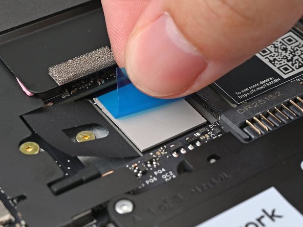
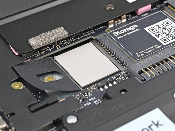
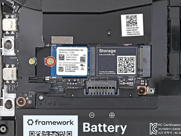
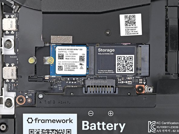
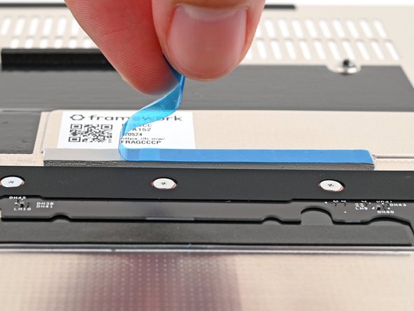
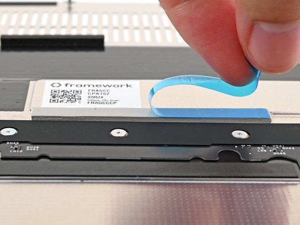
Remove the blue liner from the secondary SSD thermal pad.
-
-
-
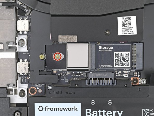
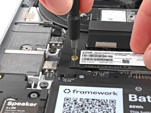
Use your Framework Screwdriver to remove the 2 mm‑long T5 Torx screw securing the secondary SSD.
-
-
-
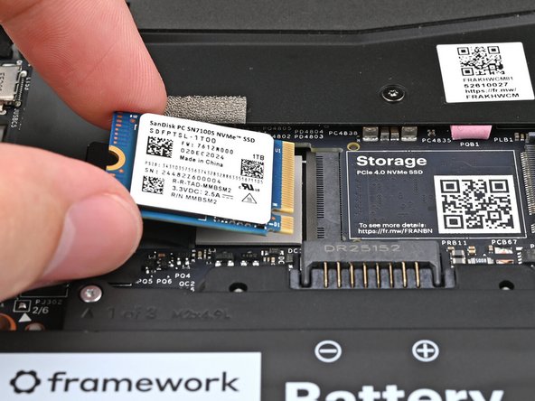
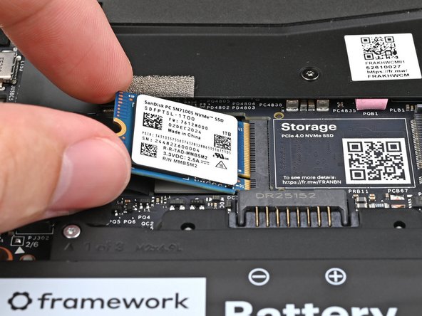
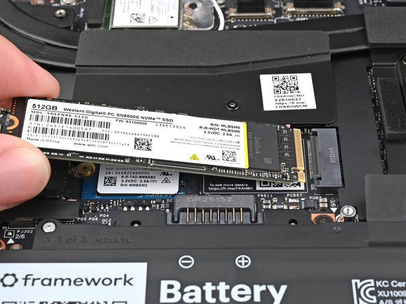
Hold the SSD by its edges. Don't touch the gold contacts with your fingers. If you do, wipe the contacts with a clean, lint-free cloth to remove any finger oils.
-
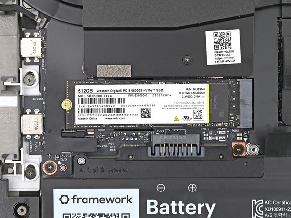
Align the SSD's gold contacts with its socket.
-
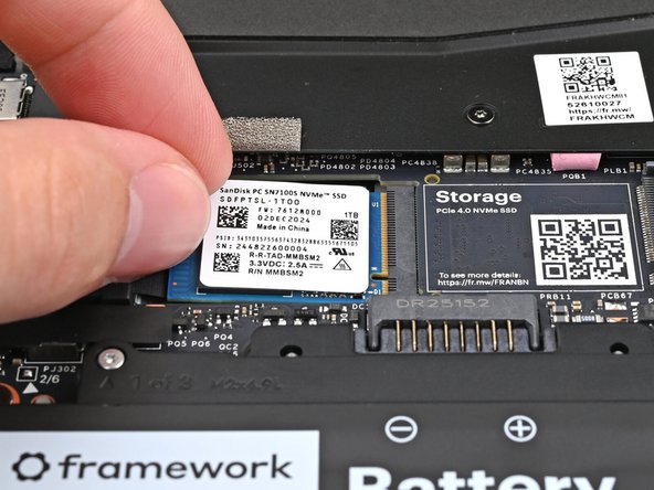
Insert the SSD partially into the socket at a shallow angle. You should still be able to see most of the gold contacts.
-
Press the SSD flat to the Mainboard.
-
-
-
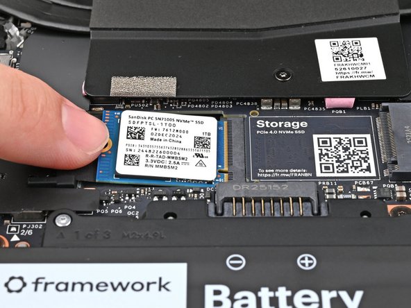
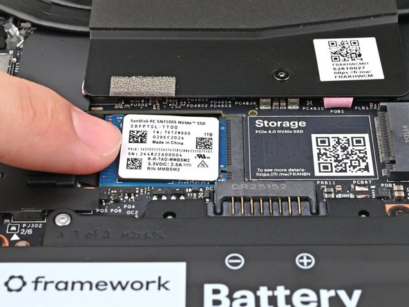
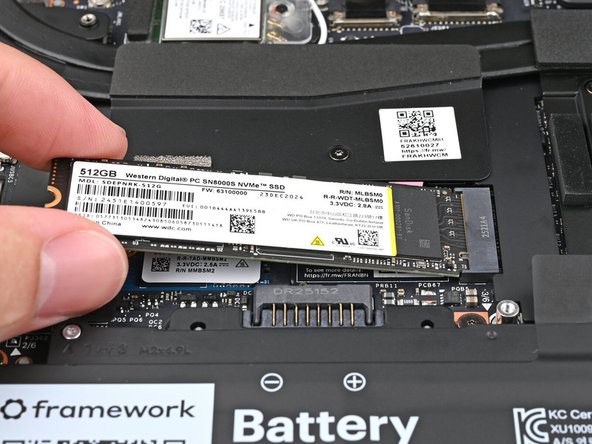
While keeping the SSD flat to the Mainboard, use your finger to slide the SSD into its socket until its golden contacts are completely covered.
-
-
-
Use a Framework Screwdriver to install the 2 mm‑long T5 Torx screw securing the secondary SSD.
-
-
-
Use your Framework Screwdriver to remove the 2 mm‑long T5 Torx screw securing the primary SSD.
-
-
-
Hold the SSD by its edges. Don't touch the gold contacts with your fingers. If you do, wipe the contacts with a clean, lint-free cloth to remove any finger oils.
-
Insert the SSD into the socket at a shallow angle. The gold contacts should mostly be covered by the socket.
-
The SSD fits into the socket in one orientation. If it doesn't feel like it fits, try flipping the module.
-
-
-
While holding the SSD flat to the Mainboard, use your Framework Screwdriver to install the 2 mm‑long T5 Torx screw securing the primary SSD.
-
-
-
If there's a blue liner on the thermal pad located on the bottom of the Mid Plate, use your fingers to peel it off.
-
-
-
Place the Mid Plate on the laptop, making sure it sits evenly on its alignment pegs.
-
-
-
Use your Framework Screwdriver to tighten the 16 T5 Torx captive screws in order (starting with 2) to secure the Mid Plate evenly.
-
-
-
Align the Mid Plate cable press connector over its socket and press down to connect it.
-
-
-
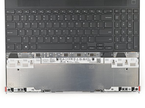
The top row of the laptop is fully customizable, but each Input Module follows the same installation procedure. The next three steps show installing the combination used in the first photo.
-
Check out this page for all of the possible Input Module combinations.
-
-
-
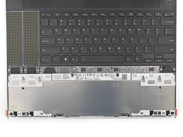
Hold the Input Module at a slight downward angle and align it with one of the dotted lines on the Mid Plate.
-
Slide the top lip of the Input Module underneath the ventilation plate and lay the module down flat to let the magnets pull it into place.
-
Make sure the alignment pegs are slotted into the Input Module and that it sits flat. Otherwise, pull the module off the laptop and readjust it.
-
-
-
Repeat the previous step for the other Input Module.
-
If you've already installed a numpad, you'll only have space for the keyboard and not another module.
-
-
-
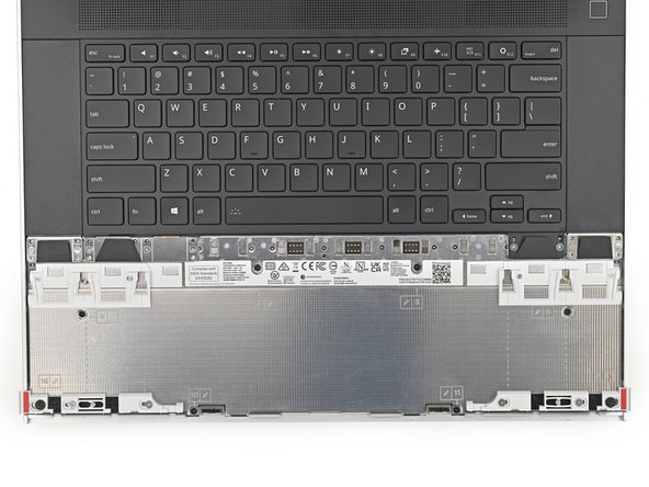
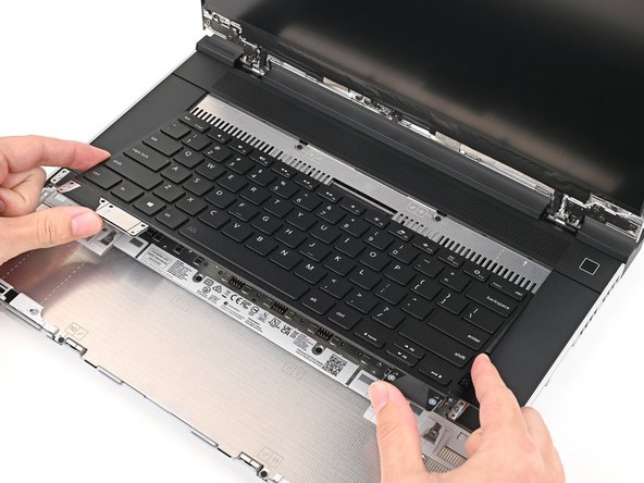
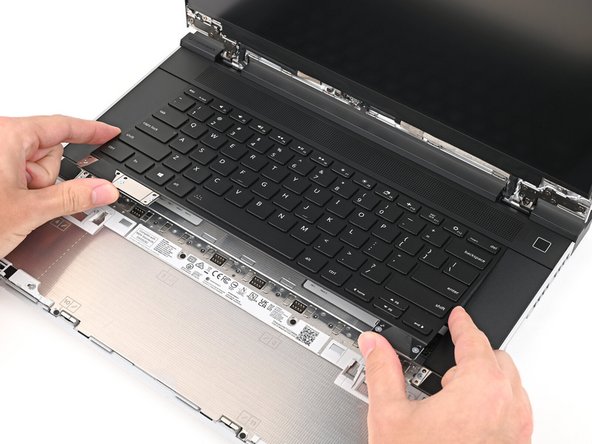
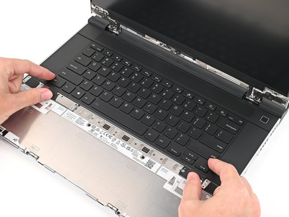
Hold the keyboard at a slight downward angle and align it with two of the dotted lines on the Mid Plate.
-
The keyboard can be placed on the left, center, or right edges of the laptop depending on which Input Modules you've installed.
-
Slide the top lip of the keyboard underneath the ventilation plate and lay the keyboard down flat to let the magnets pull it into place.
-
Make sure the alignment pegs are slotted into the keyboard and that it sits flat. Otherwise, pull the keyboard off the laptop and readjust it.
-
-
-
The bottom row of the laptop is fully customizable. The next four steps show installing the combination used in the first photo.
-
Note: for the Touchpad Module to be on the left, the keyboard can't be installed in the center.
-
-
-
Place the Touchpad Spacer over its spot on the laptop with the bottom edge overhanging slightly.
-
Slide the Touchpad Spacer towards the top of the laptop to secure it.
-
-
-
Repeat the previous step for the other Touchpad Spacer.
-
-
-
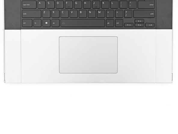
Place the Touchpad Module flat on its cutout so its clips are properly aligned.
-
Press the Touchpad Module down and slide it into place so it lines up evenly with the bottom edge of the laptop.
-
-
-
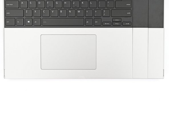
Push the Input Module latches back into place to lock them.
-
-
-
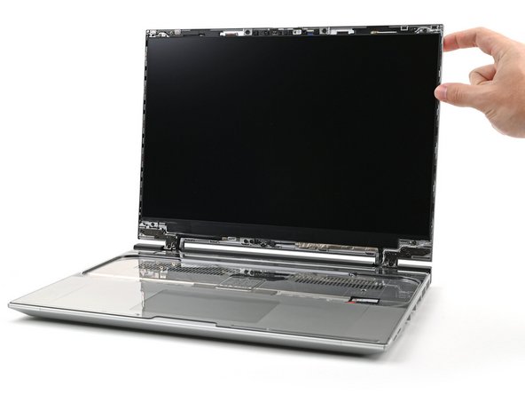
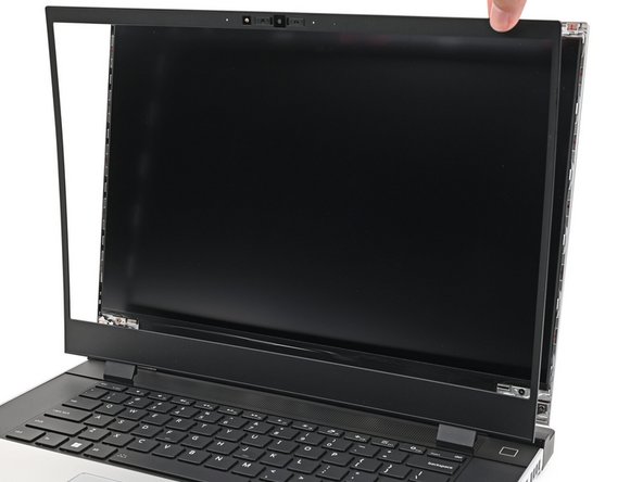
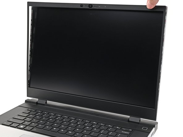
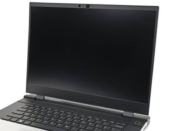
Align the bezel over the perimeter of the display and let the magnets pull the bezel into place.
-
The bezel should "snap" into place. If it doesn't, realign it and make sure it sits flush with the display.
-
-
-
Close the laptop and flip it over.
-
-
-
If you have the AMD Ryzen™ 7040 Series, click here for information on Expansion Card compatibility.
-
If you have the AMD Ryzen™ AI 300 Series, click here for information on Expansion Card compatibility.
-
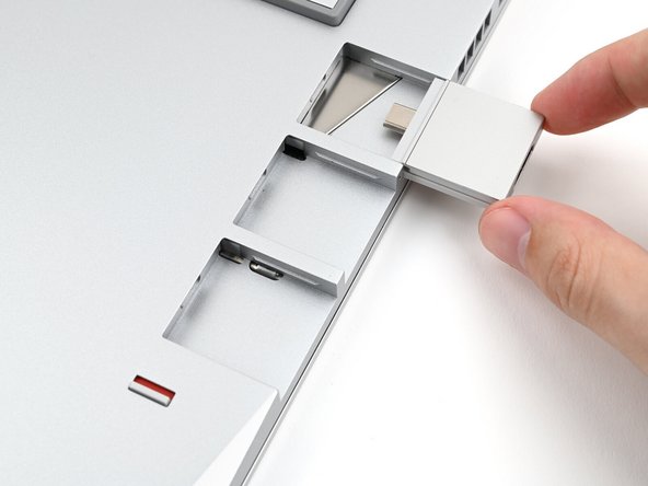
Slide an Expansion Card into an Expansion Card slot.
-
You don't need to unlock the latch to install the Expansion Cards—only when you want to remove them.
-
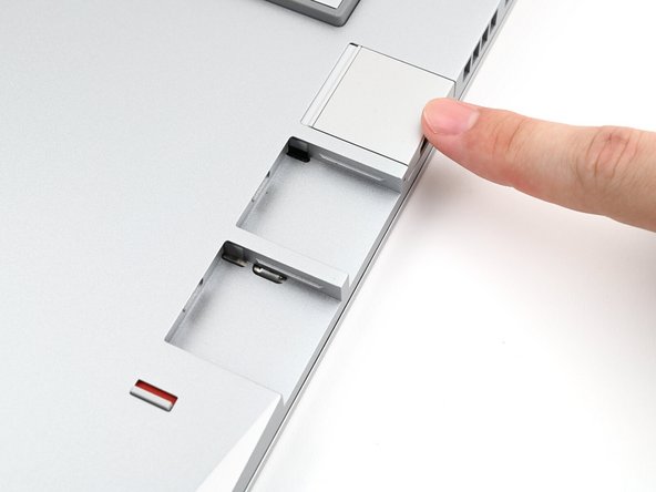
The Expansion Cards should click into place, and the front edge should be flush with the laptop.
-
Repeat for the remaining Expansion Cards along that edge.
-
-
-
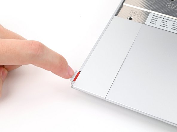
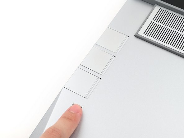
If there's a red bar showing under the Expansion Card latch, use your finger to flip the latch and lock the row of Expansion Cards above it.
-
-
-
Repeat the previous two steps for the other row of Expansion Cards.
-
-
-
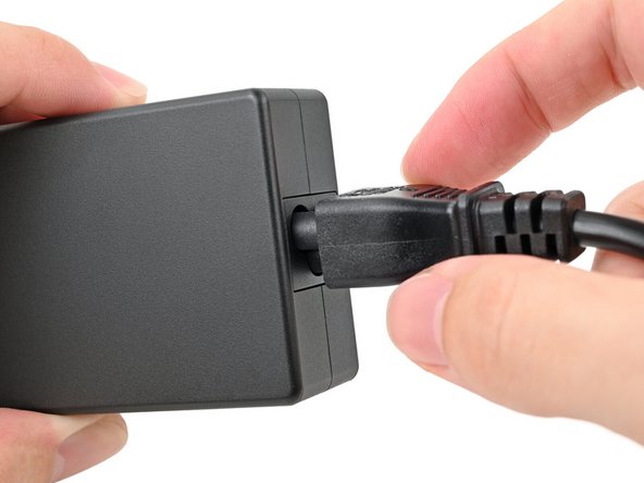
Plug the AC Cable into the Power Adapter.
-
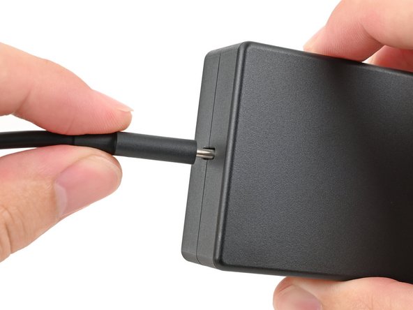
Plug the USB-C Cable into the Power Adapter.
-
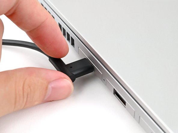
You can plug either end of the USB-C cable into the adapter.
-
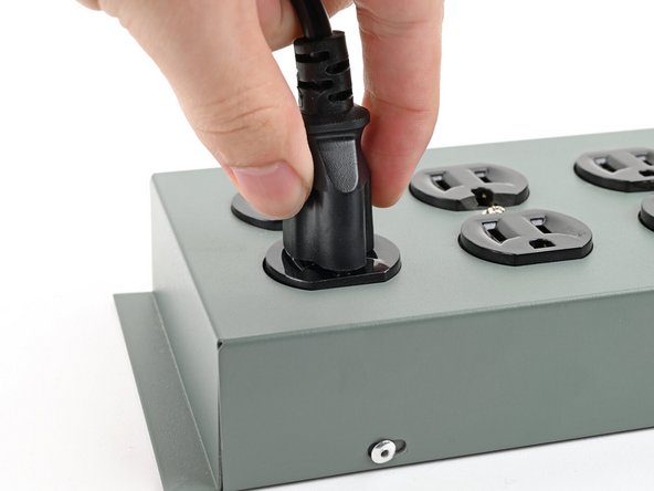
Plug the AC Cable into a power outlet.
-
-
-
Your Framework Laptop ships in shipping mode, where the battery is disabled until you plug the laptop in for the first time.
-
Plug the USB-C Cable into any USB-C port on your laptop.
-
-
-
You're done assembling your Framework Laptop! Now, you'll need to install an OS.
-
If you're installing Microsoft Windows, check out this guide.
-
If you're installing Linux, check this page for more details.
-
For drivers, firmware, and software updates, check out this page.
-


For drivers, firmware, and software updates, check out this page.
If you need help, contact Framework support.
For drivers, firmware, and software updates, check out this page.
If you need help, contact Framework support.
Cancel: I did not complete this guide.
121 other people completed this guide.
29 Comments
Mostly simple setup. Minor issues I ran across were the primary hard drive screw stripping with no effort and no plastic on the pads.
Also, instructions say you can plug the charger into any USB-C port. You should clarify this does not include the one on the Radeon GPU.
True. I thought that spot in the back was going to be an excellent place to charge from.
Few small points:
1. one screw of the midplate is "loose" doesn't really tighten completely anymore.
2. Some blue liners were not present (on the midplate for the M.2 and at the thermal plate for second storage)
3. It was quick and easy to setup! Took me 35mins while being very careful and taking my sweet time!
Lots of love for the team and the product, thanks for finally changing the game for laptops! <3
Daniel Jochemsen-Maaskant - Open Reply
Keep getting Input Module Connector Board not detected, but I've checked that plug several times and it's in all the way.
Fred Mastro - Open Reply