
Tools
Parts
-
-
Power off the Framework Laptop by navigating to the Windows icon on the bottom left and clicking on "Power" followed by "Shut down," or if on Linux, the equivalent action there.
-
-
-
Unplug your power cable from the USB-C Expansion Card in your Framework Laptop.
-
-
-
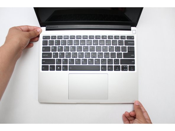
Close the lid on your Framework Laptop and place it upside down on a soft, non-marring surface, such as the bag that it shipped in.
-
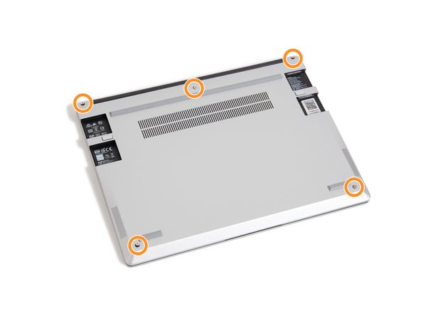
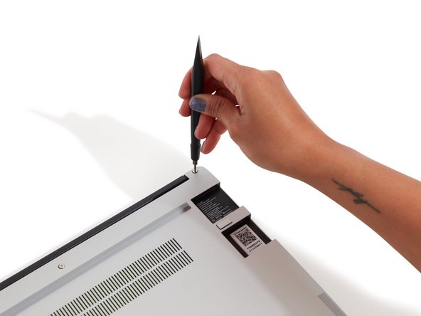
Using the T5 bit in the Framework Screwdriver, unscrew the 5 fasteners on the Bottom Cover. These fasteners will remain attached in the Bottom Cover so that you do not lose them.
-
The fastener on the bottom left (circled in red) will not unscrew as far as the others, as it is acting as a lifter for the Input Cover.
-
You'll hear this fastener start clicking as you rotate when it is unscrewed far enough.
-
Do not use a powered tool for these steps, as this will likely result in damage to the fasteners.
-
-
-
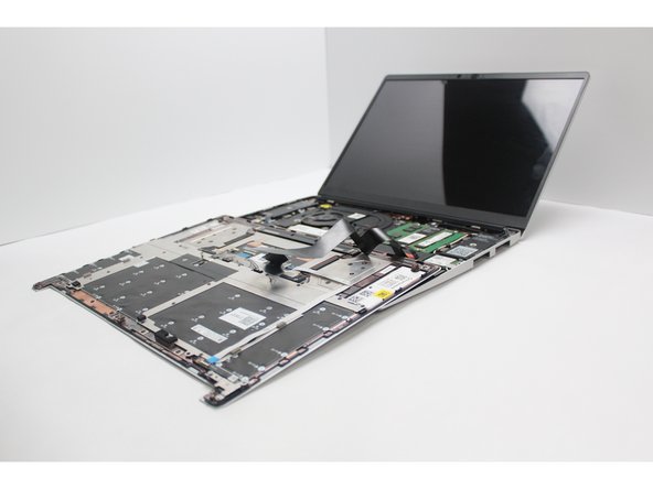
Flip the Framework Laptop back over and open the lid to around 120 degrees.
-
Important: Pull the Input Cover off carefully as it is still attached to the Mainboard via the Touchpad Cable. You don't need to disconnect this cable to do most repairs. You can just flip the Input Cover over. If you do want to disconnect it though, make sure to disconnect the Mainboard side using the finger loop over the orange label.
-
The bottom right corner of the Input Cover lifts up when the five fasteners are properly unscrewed from the previous step. You should not have to use any excessive force to remove the Input Cover.
-
Carefully lift the cover up from the bottom right corner. If you need to, you can use the spudger end of the Framework Screwdriver to lift it as well. Lift the Input Cover off the Mainboard, flip it over (keyboard side down), and place it about halfway on the Bottom Cover.
-
Be sure not to put too much force on the Touchpad Cable when doing this.
-
If the LEDs on the left and right sides of the system are flashing red when you lift off the cover, it means the system is still powered on. Make sure your power cable isn't plugged in and that you have shut down correctly.
-
Note that it may take up to 30 seconds after shutting down for the system to fully power off. Wait until the LEDs stop flashing before proceeding.
-
You should keep the Battery connector plugged in unless you need to replace the Battery, Mainboard, or Speakers. This connector is easy to accidentally damage, so it's better to not handle it.
-
-
-
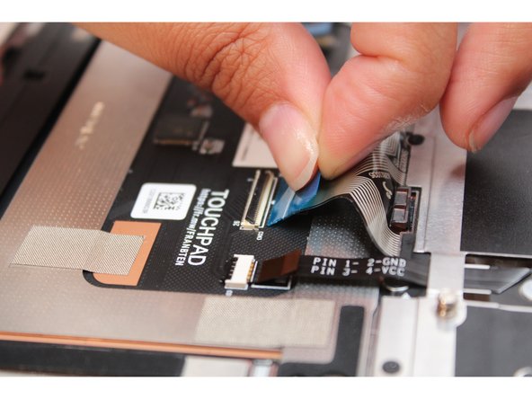
Using the spudger end of the Framework Screwdriver or your fingernail, disconnect the Touchpad Cable by flipping up the black latch up on the connector located on the Touchpad Module. This will fully disconnect the Input Cover from the Mainboard.
-
Grip the brown tab and slide the cable straight out.
-
The Input Cover is now completely disconnected from the Bottom Cover. You can safely move it away and begin working on removing the rest of the cables.
-
-
-
Using the spudger end of the Framework Screwdriver or your fingernail, disconnect the Keyboard backlight cable by flipping up the black latch up on the connector located on the Touchpad Module.
-
Grip the black pull tab on the cable and pull it straight out.
-
-
-
Using the spudger end of the Framework Screwdriver or your fingernail, disconnect the Keyboard Membrane from the Touchpad Module by fliping the black latch up.
-
Grip the blue pull tab on the cable and pull it straight out.
-
-
-
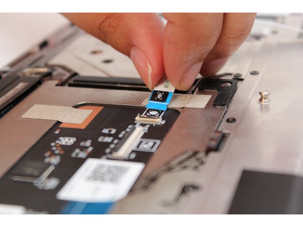
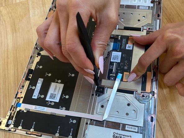
Next, disconnect the Fingerprint Cable from the Touchpad Module. Lift the black latch up using your fingernail or spudger end of the Framework Screwdriver.
-
Grip the cable and pull it straight out.
-
-
-
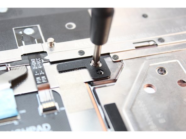
Using the PH0 bit in the Framework Screwdriver, unscrew the two fasteners holding the Touchpad Module Bracket in place as indicated in red in the first image, and remove the Bracket.
-
Then unscrew the two fasteners holding the Touchpad Module, indicated in orange.
-
Your Framework Screwdriver has a double-sided bit! One end is the T5 bit, the other end is the PH0 bit. To switch from the T5 bit to the PH0 bit pull the bit out using your fingers, flip it around, and place it back into the screwdriver!
-
-
-
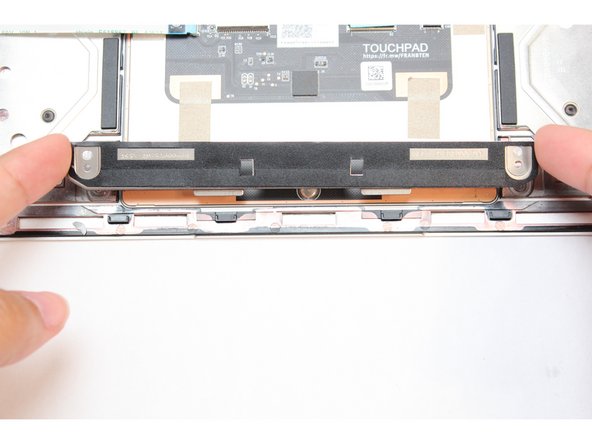
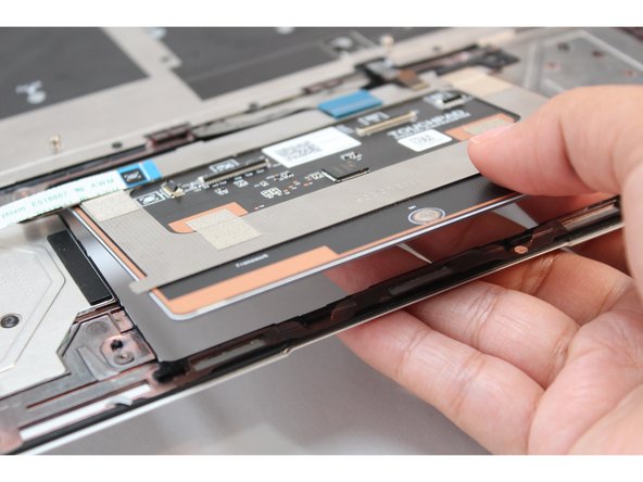
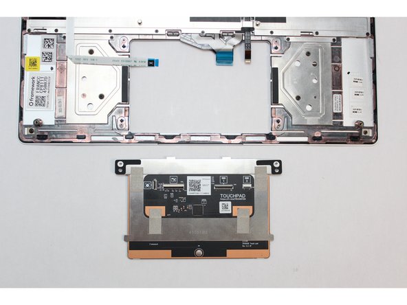
The Touchpad Module is now fully detached from the Input Cover.
-
You can now remove the module by lifting up the Input Cover and gently pushing the module up so that it is easier to grab in image one.
-
-
-
The new Touchpad comes with a clear film attached which is used for to help make sure the alignment is correct.
-
There are six tabs, outlined in red, two on the bottom, and two on each side. Fold these tabs over the edge of the Touchpad.
-
Note the green arrow on the film, this indicates the top of the Touchpad which will be the side closest to the keyboard.
-
-
-
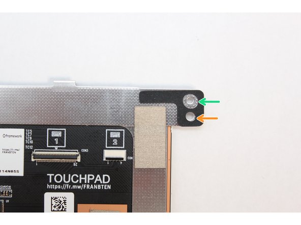
The Touchpad Module has a black spacer on the top left and right corners.
-
The larger hole is for the fastener.
-
The smaller hole is for the alignment pin which allows you to properly seat the module on the Bottom Cover.
-
Find the alignment pegs on the Bottom Cover.
-
Gently place the Touchpad module on the Bottom Cover so that the alignment pegs and holes fit into one another.
-
Be careful not to pinch the cables when inserting the new touchpad into place.
-
-
-
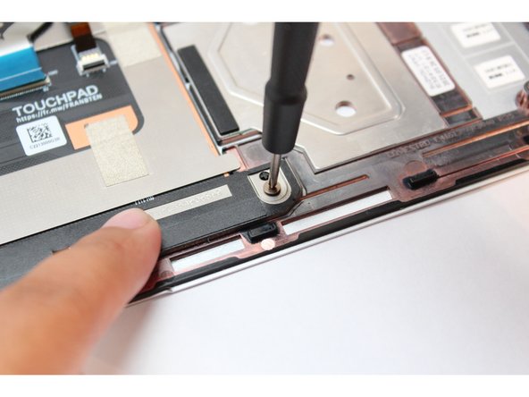
While holding the Touchpad firmly in place to make sure it is aligned, use the PH0 bit in the Framework Screwdriver to fasten the top two fasteners into place.
-
It is important that this step is carried out on a flat surface as the purpose of holding the touchpad down firmly in this step is to make sure that the alignment film tabs are keeping the Touchpad centered in the opening. If the touchpad is not pressed down flat, it could end up misaligned.
-
Make sure not to overtighten the fasteners at this step.
-
-
-
Fit the long black bracket on the bottom of the Touchpad Module as indicated in the image.
-
Using the PH0 bit in the Framework Screwdriver, fasten the two remaining fasteners back into place.
-
Do not overtighten the fasteners when attaching this bracket.
-
-
-
Now that the Touchpad is fastened to the input cover, turn the Input Cover over and gently remove the film guide.
-
You can now check that the Touchpad appears to be aligned, i.e. that the space around the sides and bottom of the Touchpad appears even.
-
If at this stage the Touchpad appears to be misaligned simply remove the fasteners in steps 13 and 14, adjust and refasten them.
-
-
-
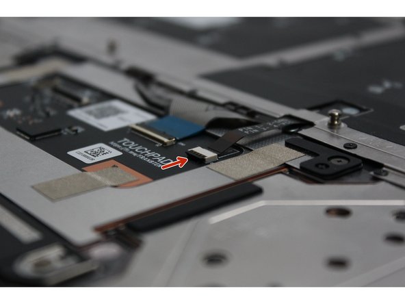
When inserting cables into their respective connectors, always make sure the black latch is flipped up so that you can slide the cable into or out of the connector.
-
Image one shows a black latch that is flipped up allowing cables to be inserted or removed.
-
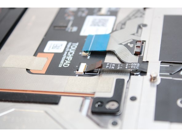
Image two shows a black latch that is flipped down which secures a cable into place. If the connector latch is secure, you will not be able to insert a cable into it.
-
-
-
Use the black pull tab and connect the Keyboard Backlight Cable into the Touchpad. Make sure the black latch is flipped up so that you can slide the cable into the connector.
-
Make sure to slide the cable in until the white line is almost at the edge of the connector.
-
Flip the black latch down to secure the cable
-
-
-
Grip the blue pull tab and connect the Keyboard Membrane cable into the Touchpad. Make sure the black latch is flipped up so that you can slide the cable into the connector.
-
Slide the cable in until the white line is almost at the edge of the connector.
-
Flip the black latch down to secure the cable.
-
-
-
Grip the Fingerprint Cable and connect it into the Touchpad Module. Make sure the black latch is flipped up so that you can slide the cable into the connector.
-
Slide the cable in until the white line is almost at the edge of the connector.
-
Flip the black latch down to secure the cable.
-
The Touchpad Module is now connected to the Input Cover.
-
-
-
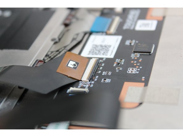
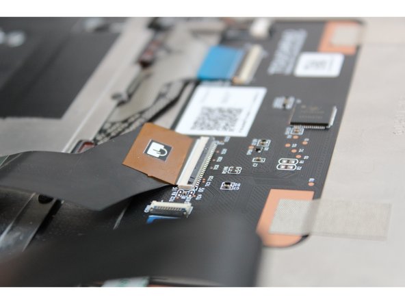
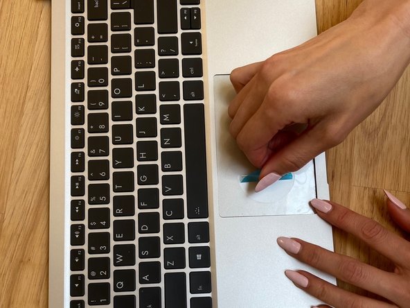
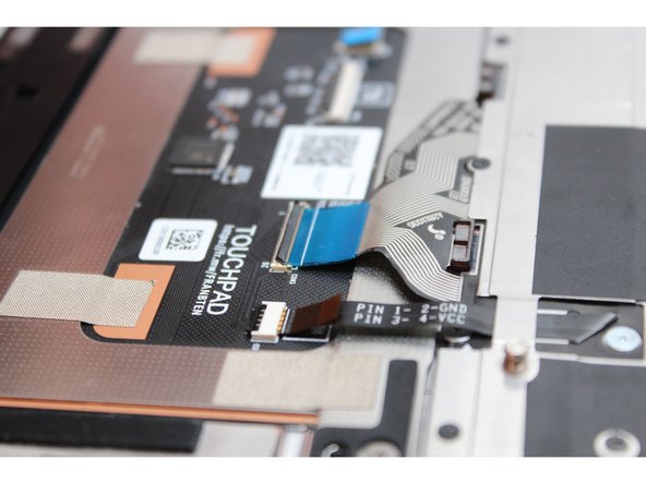
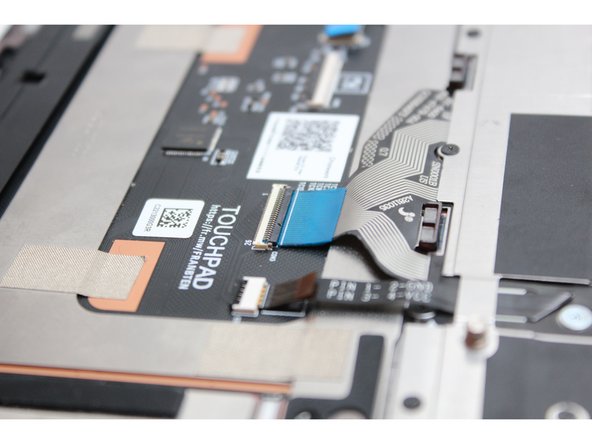
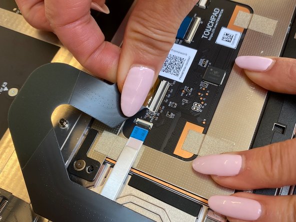
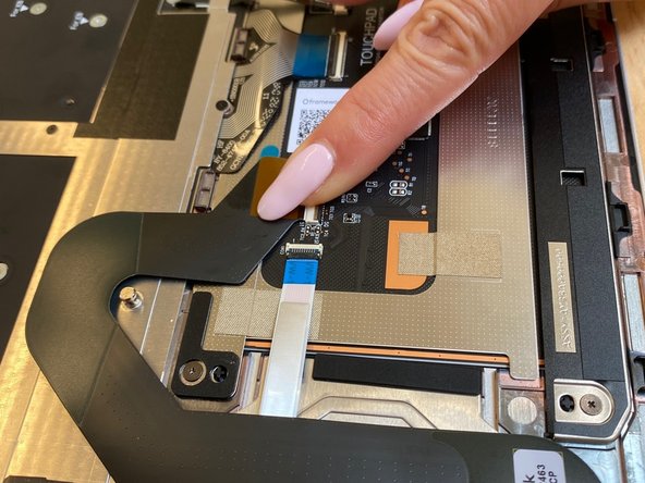
With the black latch lifted , carefully insert the Touchpad cable. The cable should be inserted far enough that the white line almost touches the receptacle as in the first image.
-
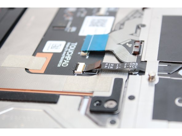
Once inserted, close the black latch to secure the connector as in the second image.
-
Before closing up the laptop, make sure that the Touchpad end of the Touchpad Cable is fully seated in the receptacle.
-
-
-
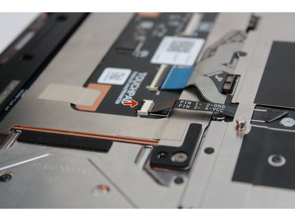
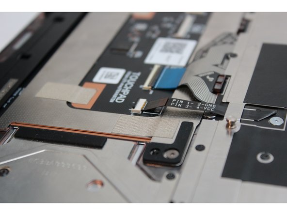
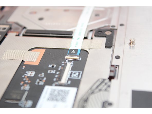
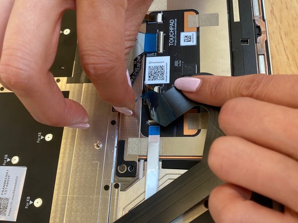
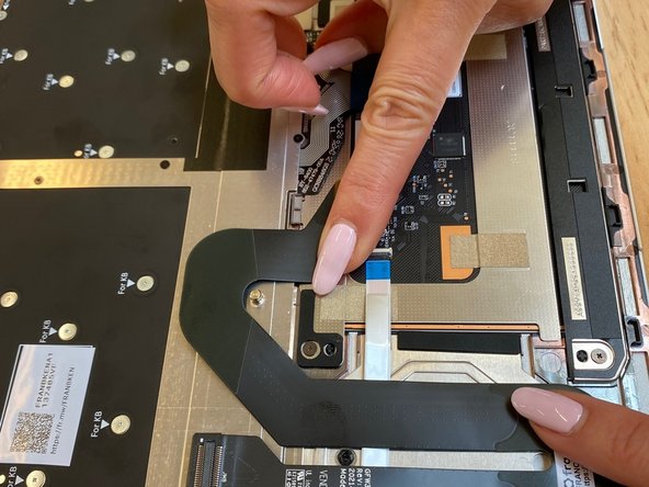
Gently peel off the blue film on the underside of the Touchpad cable as shown in the first image.
-
Attach the Touchpad cable to the Input cover by pressing gently on the cable so it sticks.
-
-
-
Flip the Input Cover over the Bottom Cover so that the keyboard is facing up and attach it to the Bottom Cover by aligning the top and bottom edges of both covers.
-
Tip: The covers are magnetic and should fit into one another easily. If you feel any resistance simply lift the Input Cover up and try again.
-
-
-
Close the Framework Laptop and turn it upside down to reveal the five fasteners on the Bottom Cover.
-
Using the T5 bit in the Framework Screwdriver, screw all 5 fasteners back into the Bottom Cover.
-
Be sure to not overtighten the fasteners.
-


- To purchase a Framework Laptop visit the Framework website
- Want to learn more about the Framework Laptop? Take a look at our blog
- If you have any questions or concerns, feel free to reach out to Framework Support
- To purchase a Framework Laptop visit the Framework website
- Want to learn more about the Framework Laptop? Take a look at our blog
- If you have any questions or concerns, feel free to reach out to Framework Support
Cancel: I did not complete this guide.
10 other people completed this guide.
5 Comments
Not sure if it's just the tools I got from B&H photo, but the PH00 bit from them was the far better size vs PH0.
B&H T5 worked like a charm, so good that I have it as a backup.
John Veenstra - Open Reply
Excellent guide! Thank you, took me just a few min!
Giorgi Maghlakelidze - Resolved on Release Reply
This guide is extremely useful for anyone looking to replace their laptop touchpad. The clear instructions and detailed images made the process straightforward and easy to follow for me.
Bajrang Waghmare - Resolved on Release Reply
This guide is extremely useful for anyone needing to replace their touchpad. The clear instructions and detailed images made the replacement process straightforward and manageable.
Shiv Teckchandani - Resolved on Release Reply
The touchpad replacement guide provided in this blog is incredibly useful. As someone who values being able to repair and maintain my devices, having access to clear instructions on how to replace a touchpad is invaluable. The detailed explanations and step-by-step instructions offered here give me confidence in tackling such repairs effectively. Thank you for sharing this valuable resource.
Shiv Teckchandani - Resolved on Release Reply