
Introduction
Here it is, the Framework Laptop Top Cover replacement guide! Before you proceed with the replacement, here is a helpful tip: we recommend that you store each fastener in a dedicated space (such as a cup) as you are removing them. It is important to not mix up or lose any fasteners.
Replacing the Top Cover or upgrading to the Top Cover (CNC) takes a bit more time than some other modules because of just how much is attached to it.
If you have questions or run into any issues, check out the Support pages.
Tools
Parts
No parts specified.
-
-
Power off the Framework Laptop by navigating to the Windows icon on the bottom left and clicking on "Power" followed by "Shut down," or if on Linux, the equivalent action there.
-
-
-
Unplug your power cable from the USB-C Expansion Card in your Framework Laptop.
-
-
-
Close the lid on your Framework Laptop and place it upside down on a soft, non-marring surface, such as the bag that it shipped in.
-
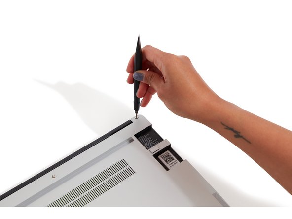
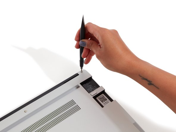
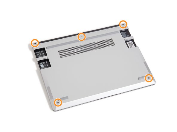
Using the T5 bit in the Framework Screwdriver, unscrew the 5 fasteners on the Bottom Cover. These fasteners will remain attached in the Bottom Cover so that you do not lose them.
-
The fastener on the bottom left (circled in orange) will not unscrew as far as the others, as it is acting as a lifter for the Input Cover.
-
You'll hear this fastener start clicking as you rotate when it is unscrewed far enough.
-
-
-
Flip back over, and open the lid to 120 degrees.
-
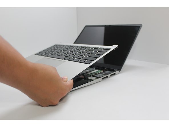
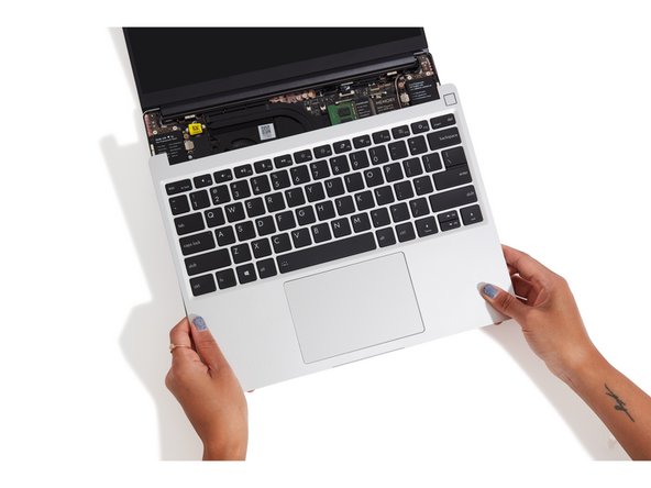
Important: Pull the Input Cover off carefully as it is still attached to the Mainboard via the Touchpad Cable. You don't need to disconnect this cable to do most repairs. You can just flip the Input Cover over. If you do want to disconnect it though, make sure to disconnect the Mainboard side using the finger loop over the orange label.
-
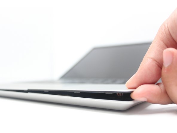
The bottom right corner of the Input Cover lifts up when the five fasteners are properly unscrewed from the previous step. You should not have to use any excessive force to remove the Input Cover.
-
Carefully lift the cover up from the bottom right corner. If you need to, you can use the spudger end of the Framework Screwdriver to lift it as well. Lift the Input Cover off the Mainboard, flip it over (keyboard side down), and place it about halfway on the Bottom Cover.
-
Be sure not to put too much force on the Touchpad Cable when doing this.
-
If the LEDs on the left and right sides of the system are flashing red when you lift off the cover, it means the system is still powered on. Make sure your power cable isn't plugged in and that you have shut down correctly.
-
Note that it may take up to 30 seconds after shutting down for the system to fully power off. Wait until the LEDs stop flashing before proceeding.
-
You should keep the Battery connector plugged in unless you need to replace the Battery, Mainboard, or Speakers. This connector is easy to accidentally damage, so it's better to not handle it.
-
-
-
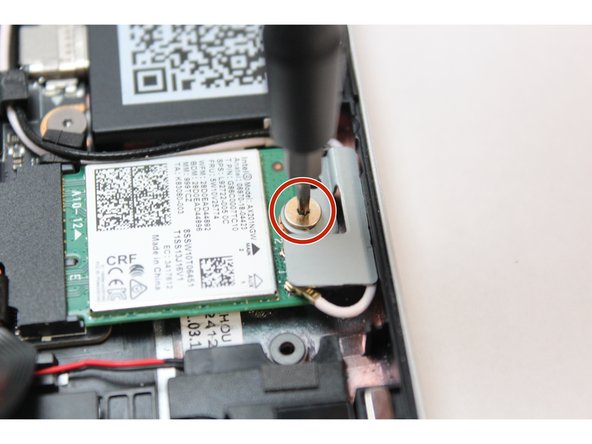
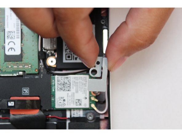
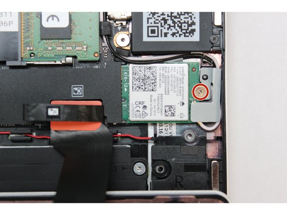
Using the T5 bit in the Framework Screwdriver, unscrew the fastener on the WiFi module.
-
Remove the fastener and gently lift off the WiFi Bracket.
-
The WiFi module will lift up at an angle. Slide it out of the receptacle.
-
-
-
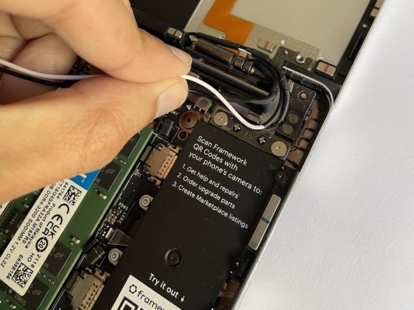
Disconnect the antenna cables from the WiFi card.
-
Pull the antenna cables out of the rubber routing guides and the routing channels near the hinge.
-
-
-
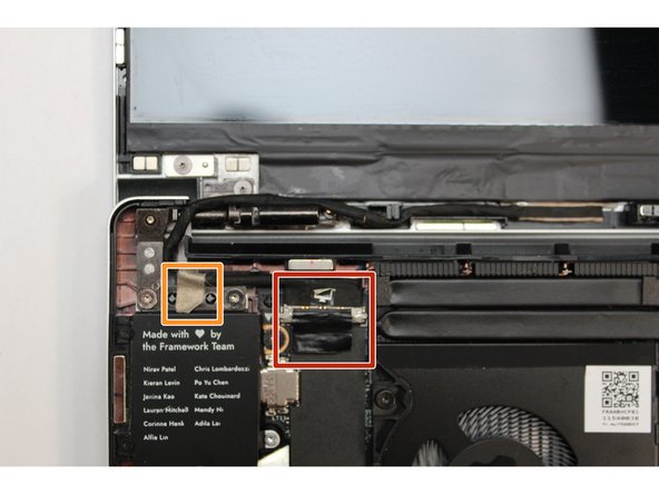
Disconnect Webcam Cable from Mainboard and pull the cable out of the routing channels near the hinge.
-
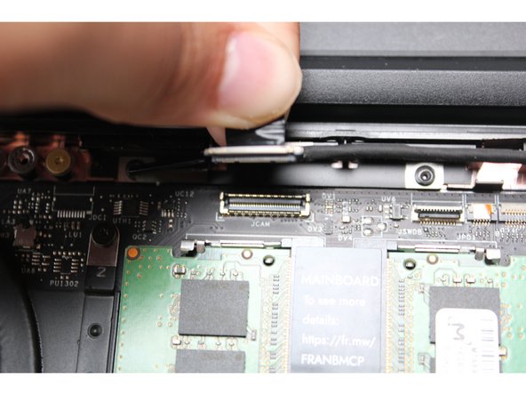
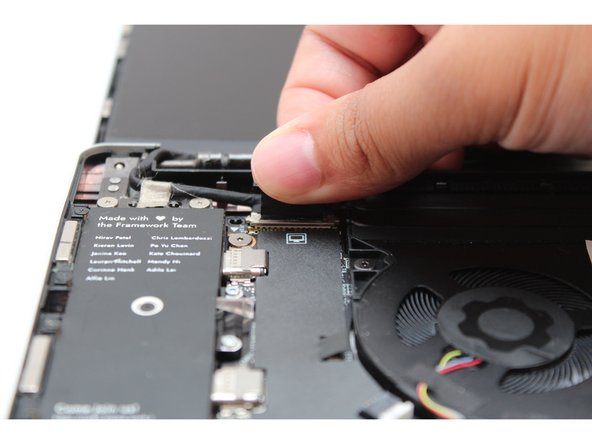
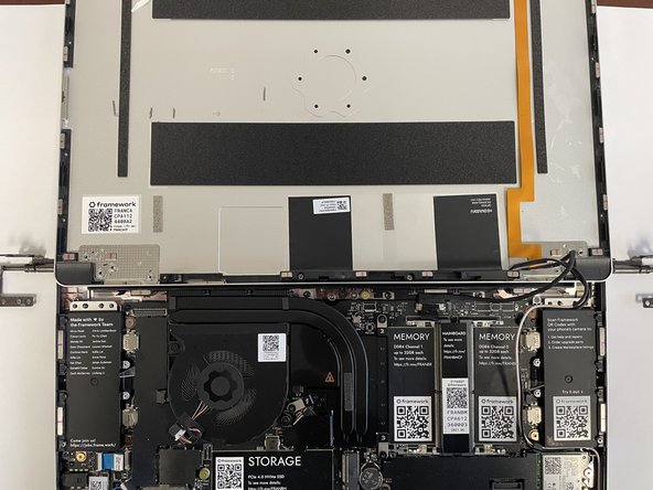
Disconnect the Display Cable from the Mainboard.
-
Find the black Display Cable that connects the display to the mainboard. Unplug the cable by pulling it directly upwards using the black pull tab.
-
Carefully lift up the silver grounding tape that is holding the Display Cable to the hinge.
-
Free the Display Cable from the Bottom Cover and carefully remove it from any routing pegs. It will remain connected to the display.
-
-
-
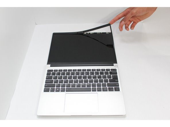
Open the Framework Laptop 180 degrees to remove the Bezel.
-
Be careful to check that the back left and right fasteners that you unscrewed earlier don't get caught on the lid as you open it to 180 degrees.
-
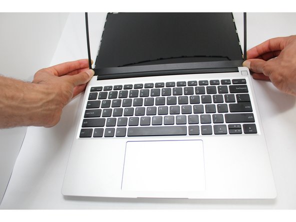
The Framework Bezel is attached by magnets so you will not require any tools to remove it. Just use your fingernail and pry the Bezel away from the display from one of the top corners of the Framework Laptop.
-
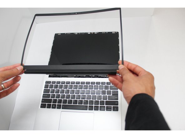
Once the Bezel starts peeling off towards the bottom of the Display, lift it up using caution. There are small patches of double-sided tape on the Bezel along the bottom edge of the Display, so take extra care when lifting that section off.
-
-
-
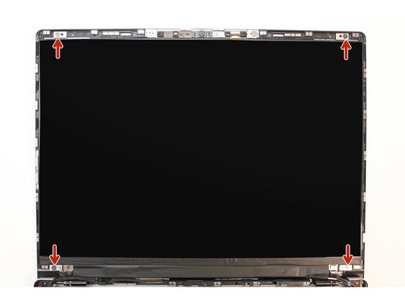
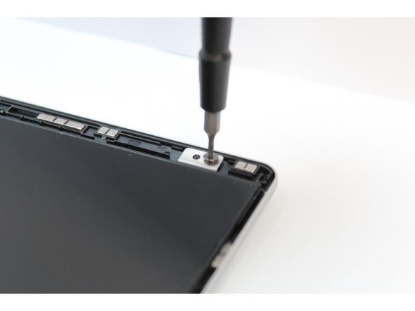
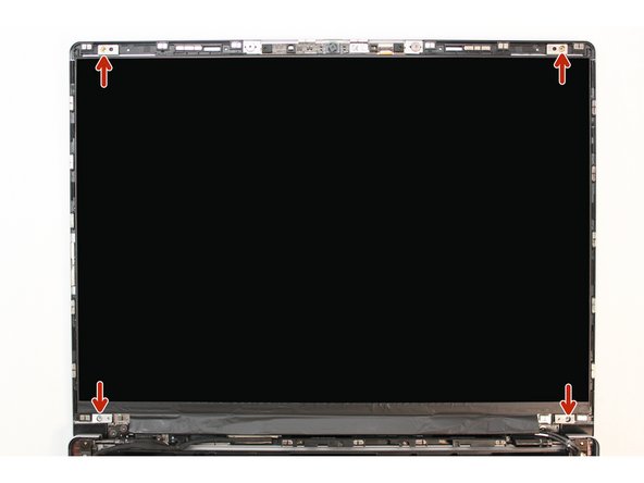
Using the T5 bit in the Framework Screwdriver, unscrew the 4 fasteners connecting the Display to the Top Cover.
-
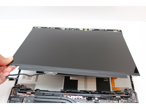
The Display is now fully unattached to the Top Cover, you can gently lift it up from the corner using your fingernail.
-
Be sure to only handle the Display by the side edges and avoid touching the bottom area.
-
-
-
Check if your new Top Cover has a Webcam Module already installed. If it does, you can skip over this step.
-
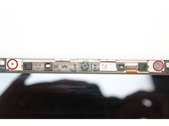
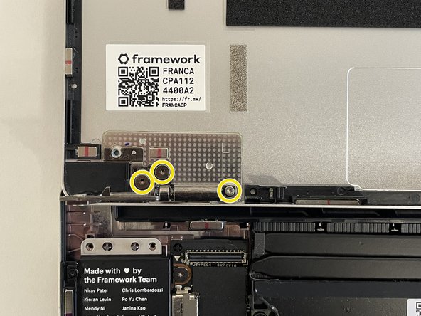
Using the T5 Bit in the Framework Screwdriver, unscrew the two fasteners connecting the Webcam Module to the Top Cover.
-
Remove the magnetic washers under the screws.
-
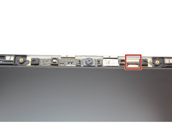
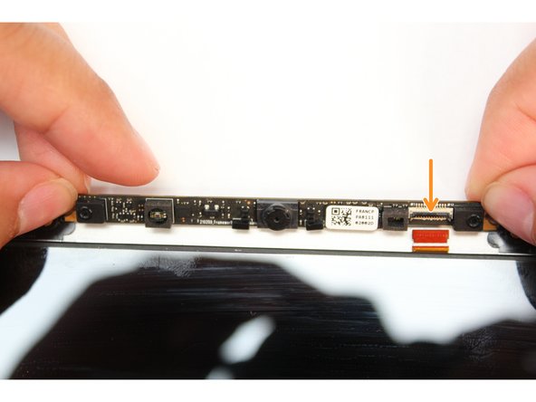
Flip up the latch on the Webcam Cable
-
Using your fingernail or the spudger side of the Framework Screwdriver, flip up the black latch on the Webcam Cable to disconnect it.
-
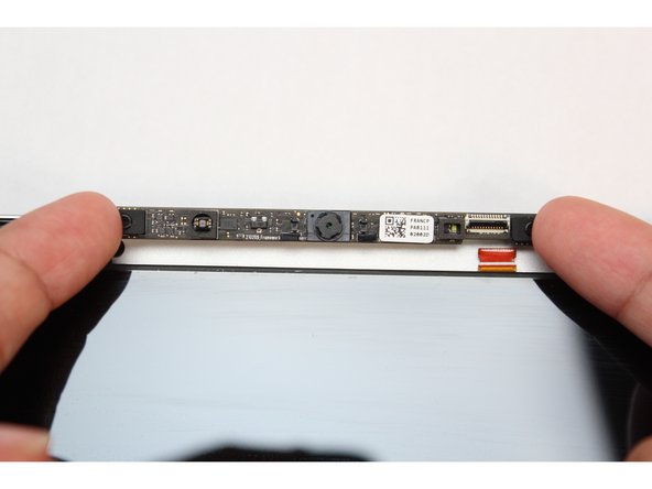
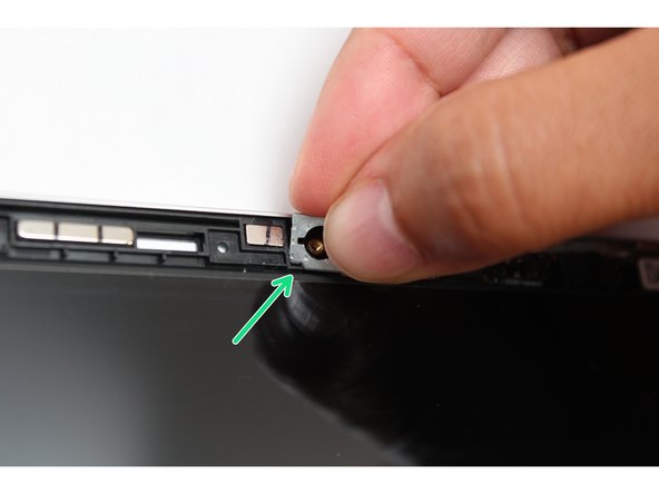
Remove the Webcam module.
-
Lift the module out of the cover by handling the module only by the edges.
-
The Webcam Module is now fully disconnected from the Top Cover.
-
-
-
If your new Top Cover has Hinges attached, you can choose to either use those or remove them and keep the existing Hinges that are on your laptop. The following steps assume you are keeping the Hinges that are already on your laptop.
-
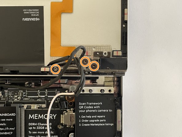
Unscrew the three fasteners on the right Hinge using the T5 bit in your Framework Screwdriver.
-
Repeat this for the three fasteners on the left Hinge.
-
Lift up the Laptop slightly and remove the now disconnected Top Cover, which will have the antenna and camera cables still attached.
-
-
-
Take the new Top Cover and place it under the Hinges.
-
Fasten the three fasteners back in on the left Hinge.
-
Fasten the three fasteners back in on the right Hinge.
-
-
-
If your new Top Cover already has a Webcam Module, you can skip this step.
-
Make sure the black latch on the connector is flipped up so that you can slide the Webcam Cable into the connector. Slide the cable straight in until the white line is almost at the edge of the connector.
-
Flip the black latch down to secure the cable in place.
-
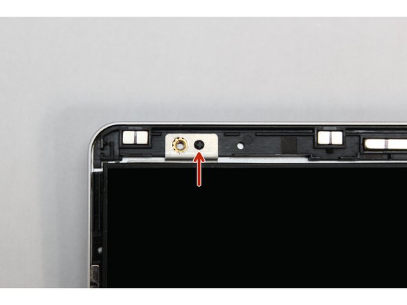
Find the two washers and orient them so that the notch on both washers are located at the bottom corner as indicated with the red arrows in the first image. These need to be aligned with the notch on the Top Cover.
-
Using the T5 Bit in the Framework Screwdriver screw in both fasteners.
-
Be sure to not over-tighten the fasteners.
-
-
-
There are four alignment pins located on the Top Cover. They are located right next to the four fastener slots. Place the silver brackets connected to Display directly over the pins.
-
Be sure to only handle the Display by the side edges and avoid touching the bottom area.
-
Using the T5 bit in the Framework Screwdriver screw the four fasteners into place.
-
Be sure to not over tighten the fasteners.
-
-
-
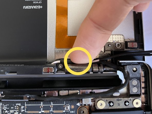
Route the Display Cable through the channel in the Top Cover, over the left hinge, and plug it back into the Mainboard.
-
On the Top Cover (CNC), this is a flat channel without a hook, so just make sure the cable is laying mostly flat inside it.
-
Route the Antenna Cables over the right hinge, through the routing channels near the hinge, through the rubber channels on the Mainboard.
-
Route the Webcam Cable over the right hinge, through the routing channels, and plug it back into the Mainboard.
-
-
-
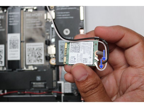
Carefully connect the black and white WiFi antenna cables into their respective sockets on the module. Make sure to align them well before applying force to click them into place, as the connectors are small and fragile.
-
-
Once both the black and white WiFi Antenna cables are connected to the module, make sure they are rotated downwards as indicated in the second picture with the blue arrows.
-
While keeping a finger on top of the antennas to hold them in place, insert the WiFi module into the socket on the Mainboard.
-
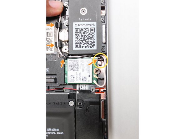
Once the module is properly inserted into the Mainboard, carefully route both the black and white WiFi Antenna cables into the black rubber routers as indicated in the first image.
-
Place both the cables behind the metal structure located near the top right of the WiFi module as well.
-
The antenna cables should not touch the Speaker located below. Use the spudger end of the Framework Screwdriver to carefully push the white cable away from the Speaker if it is touching it.
-
-
-
Place the WiFi Bracket over the WiFi module and place the fastener in the hole. Using the T5 bit in the Framework Screwdriver, screw the fastener into place.
-
Be sure to not over-tighten the fastener.
-
-
-
Align the corners of the Bezel to the display and place it down. The Bezel is attached by magnets and should easily click into place.
-
Make sure that all of the corners and edges of the Bezel are fully connected to the Top Cover. If the corners are not aligned, carefully lift up the part of the Bezel and guide it into place.
-
-
-
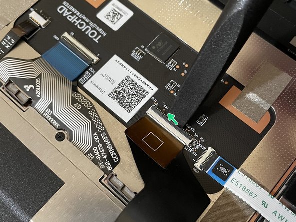
Before closing up the laptop, make sure that the Touchpad end of the Touchpad Cable is fully seated in the receptacle.
-
The cable should be inserted far enough that the white line almost touches the receptacle.
-
If it is not inserted far enough, you'll need to flip up the black latch on the other side of the connector, slide the cable in further, and then close the black latch again.
-
-
-
Flip the Input Cover over the Bottom Cover so that the keyboard is facing up and attach it to the Bottom Cover by aligning the top and bottom edges of both covers.
-
The covers are magnetic and should fit into one another easily. If you feel any resistance simply lift the Input Cover up and try again.
-
-
-
Close the Framework Laptop lid and place it upside down to reveal the fasteners on the Bottom Cover.
-
Using the T5 bit in the Framework Screwdriver, screw all 5 fasteners back into the Bottom Cover.
-
Be sure to not over-tighten the fasteners.
-


- To purchase a Framework Laptop visit the Framework website
- Want to learn more about the Framework Laptop? Take a look at our blog
- If you have any questions or concerns, feel free to reach out to Framework Support
- To purchase a Framework Laptop visit the Framework website
- Want to learn more about the Framework Laptop? Take a look at our blog
- If you have any questions or concerns, feel free to reach out to Framework Support
Cancel: I did not complete this guide.
7 other people completed this guide.