Introduction
Use this guide to replace or upgrade the Mainboard in your Framework Laptop 13. If you are swapping the Mainboard on your Framework Laptop 13 Pro, you can follow this guide instead.
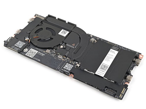
The Mainboard (aka motherboard) is responsible for the primary functions for your Laptop. If you want to upgrade your processor, you'll need to replace the Mainboard.
Replacement Mainboards come with a pre-installed heatsink but don't come with pre-installed Storage, Memory (SO-DIMM or LPCAMM2), or Wi-Fi modules. This guide will show how to transfer them to your new Mainboard.
If you're running Windows:
- Make sure you back up your data.
- If you’re running a Pro version of Windows, follow these directions to suspend BitLocker.
- If you're running a Home version of Windows and have enabled Windows Device Encryption, you'll want to disable it. To disable it, press Win + I to open Settings and select Privacy & Security. Then, click on Device Encryption on the right panel and toggle the setting to Off.
- Find your product key or link your Windows license to a Microsoft account to make sure you can re‑activate Windows after the change.
Tools
Parts
-
-
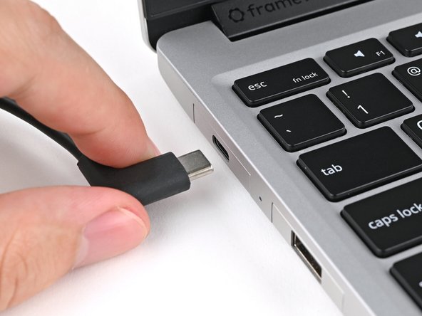
Unplug all cables and fully shut down your laptop from the OS.
-
-
-
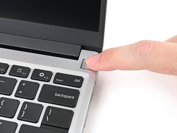
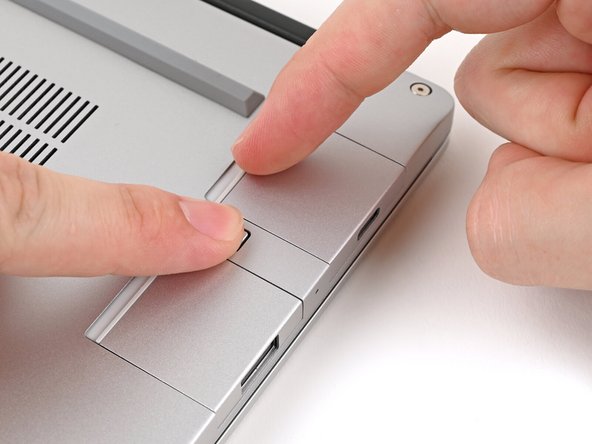
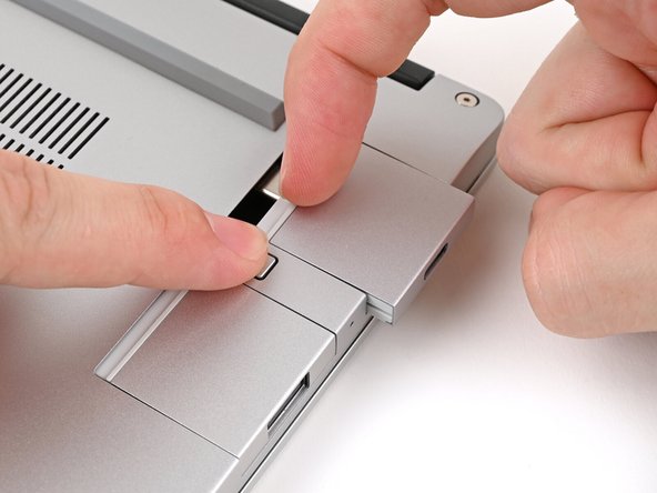
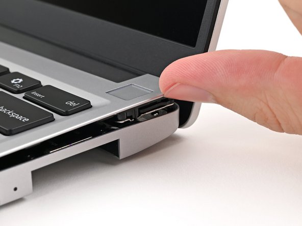
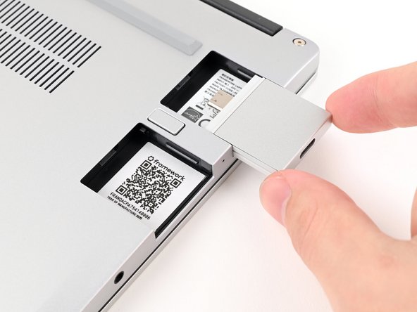
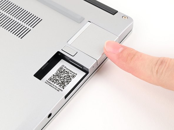
While pressing down the release button, grip the lip of the Expansion Card and pull it out of its slot to release it.
-
This might take some initial force. If you're having trouble, make sure you're fully pressing down the release button.
-
-
-
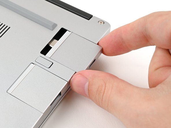
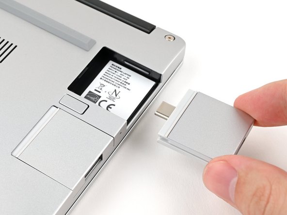
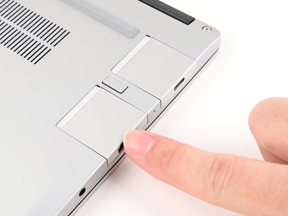
Slide the Expansion Card out of its slot and remove it.
-
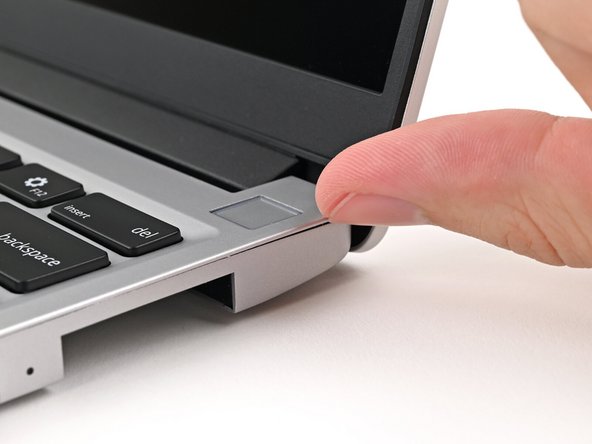
Remove the remaining Expansion Cards.
-
-
-
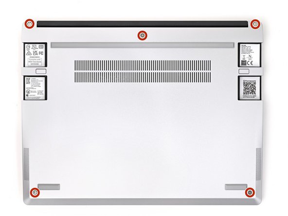
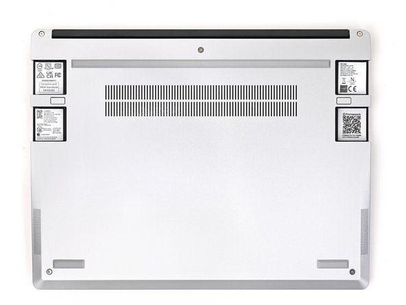
Use your Framework Screwdriver to loosen the five captive T5 Torx screws securing the Input Cover.
-
The screw will make an audible "clicking" sound once it's fully loosened.
-
-
-
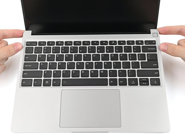
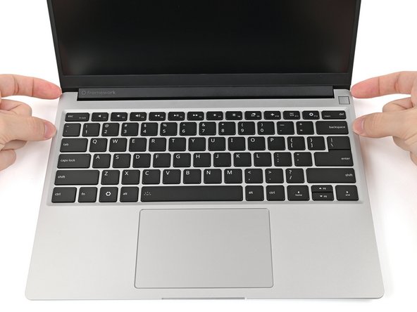
Flip over the laptop and open it.
-
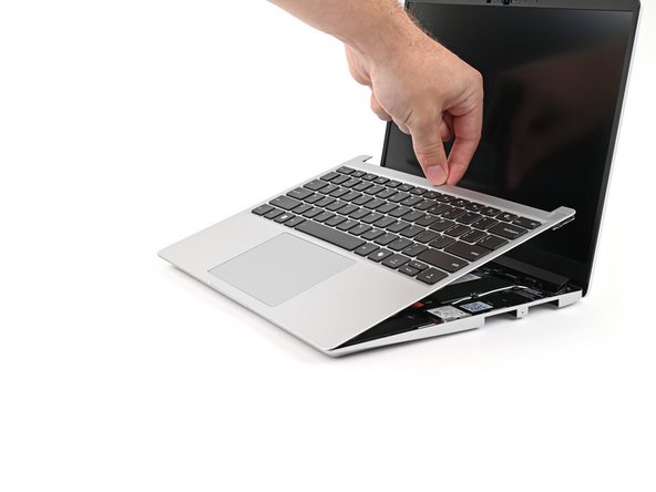
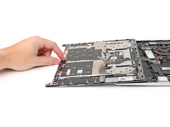
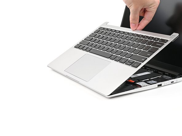
Use your fingers to lift the Input Cover up and release it from its magnets.
-
Don't fully remove the Input Cover yet, as it's still attached by the Touchpad Cable.
-
-
-
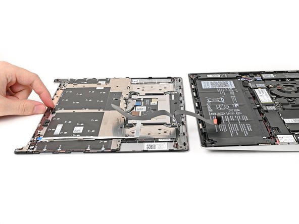
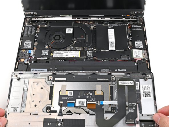
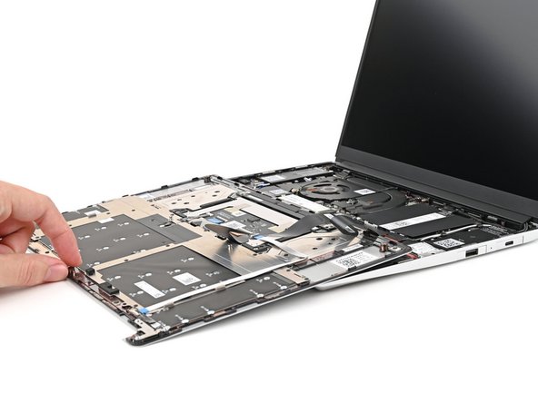
Flip the top of the Input Cover so the Keyboard is facing down.
-
Rest the Input Cover over the Battery, making sure the Touchpad Cable isn't being strained.
-
If the LEDs on the left and right sides of the Mainboard are flashing, then your laptop is still powered on. Make sure your laptop is completely powered off before continuing.
-
-
-
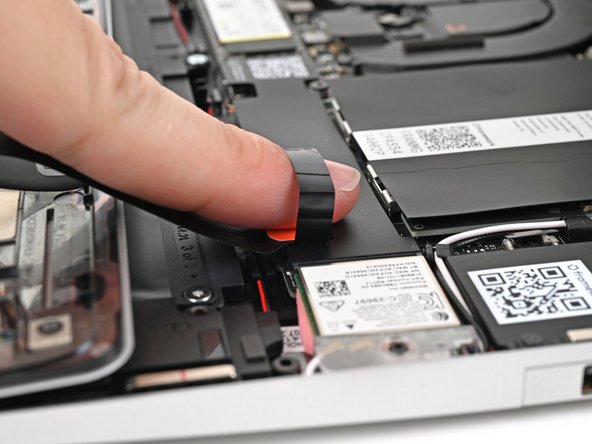
Insert your finger into the Touchpad Cable press connector loop.
-
Lift up to disconnect the Touchpad Cable from the Mainboard.
-
-
-
Remove the Input Cover.
-
-
-
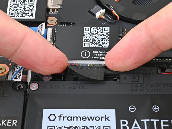
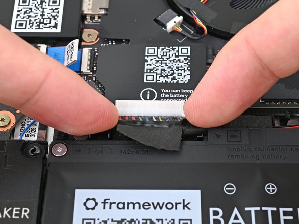
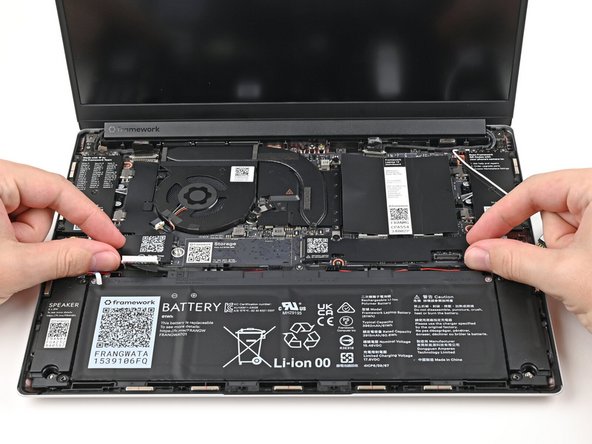
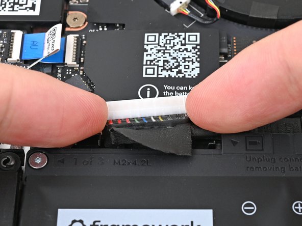
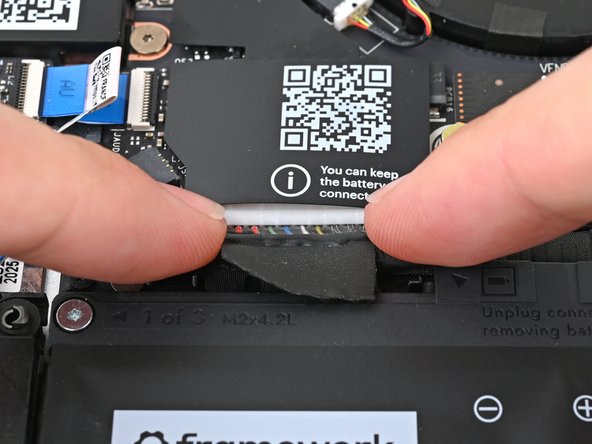
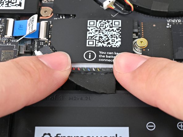
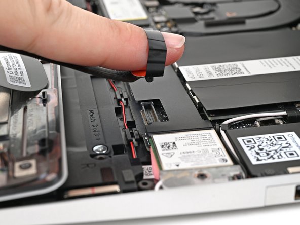
When disconnecting the Battery, make sure you slide its connector straight out of its socket or else you risk bending the socket's pins.
-
Use your fingers to grip the edges of the Battery connector and slide it straight out of its socket to disconnect the Battery.
-
-
-
If you're removing a LPCAMM2 module, follow the next three steps. If you're removing SO-DIMM Memory modules, skip here.
-
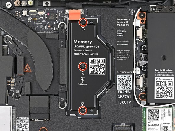
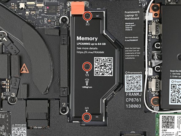
Use your Framework Screwdriver to loosen the captive T5 Torx screws securing the LPCAMM2 Memory Cover in reverse order from 3–1.
-
-
-
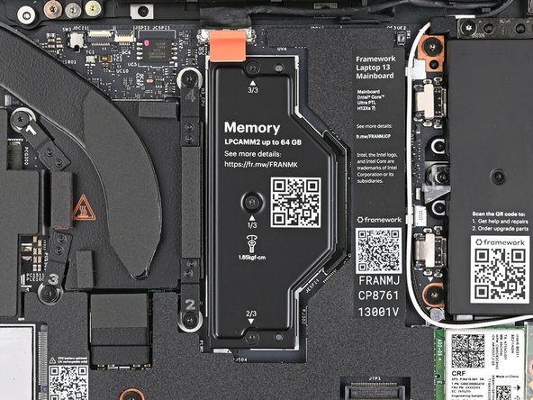
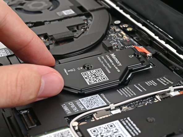
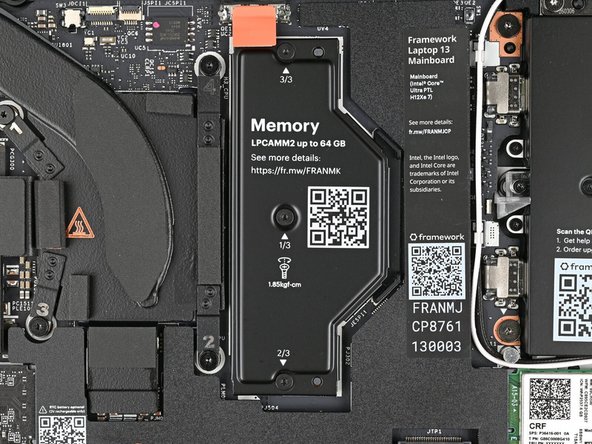
Lift the LPCAMM2 Memory Cover straight off the memory and remove it.
-
-
-
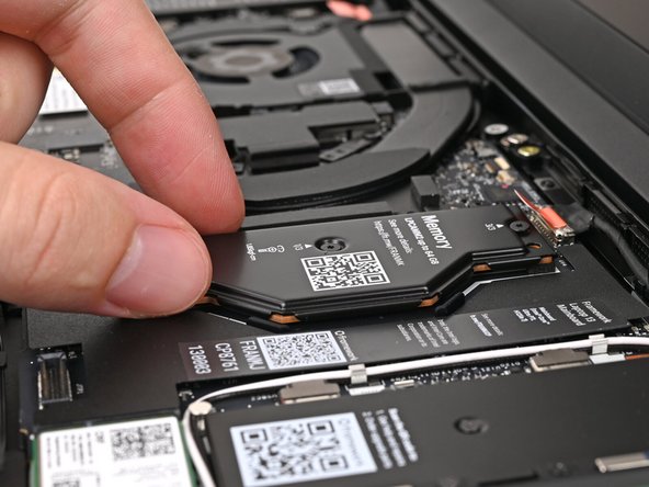
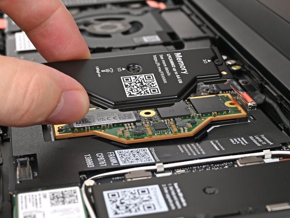
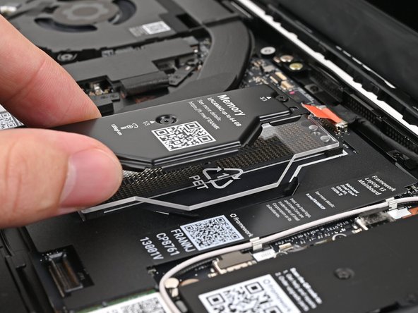
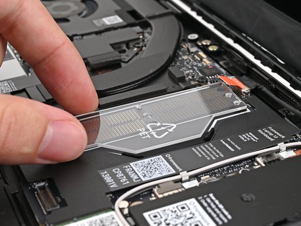
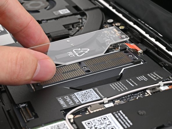
Grip the LPCAMM2 module by its edges and lift it straight off its alignment pegs to remove it.
-
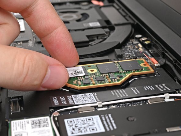
Avoid touching the Interposer below the module. If the Interposer accidentally shifts, grab it by its edges to place it back into its alignment pegs.
-
Make sure there's no dust or debris on top of the Interposer before continuing.
-
-
-
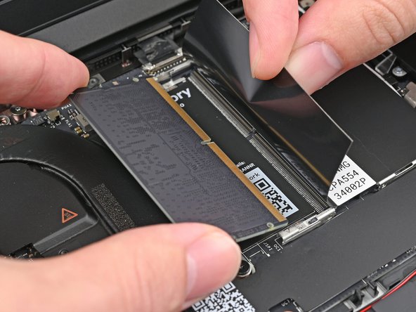
Depending on your Mainboard's generation, you might not have black flaps covering your memory.
-
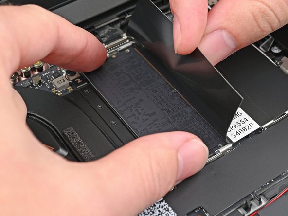
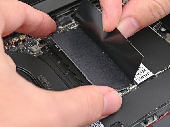
While holding up the black flap covering the left memory module, push the two metal arms on each side of the module outward until they disengage and the module pops up at a shallow angle.
-
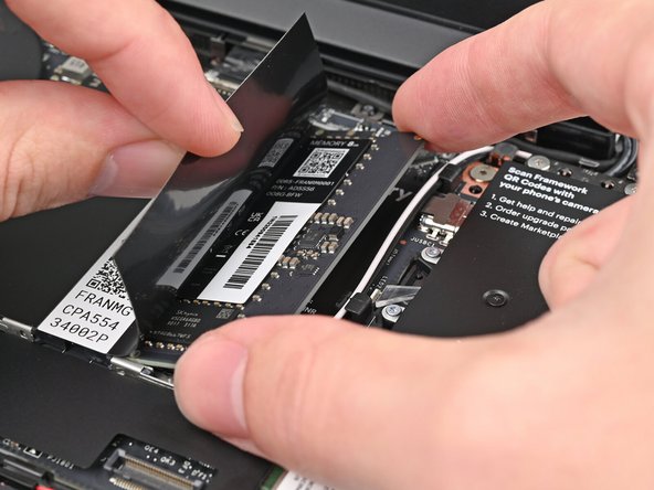
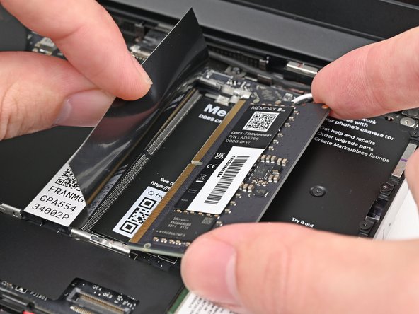
Slide the memory module out of its socket and remove it.
-
-
-
Repeat the previous step for the right module.
-
-
-
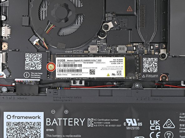
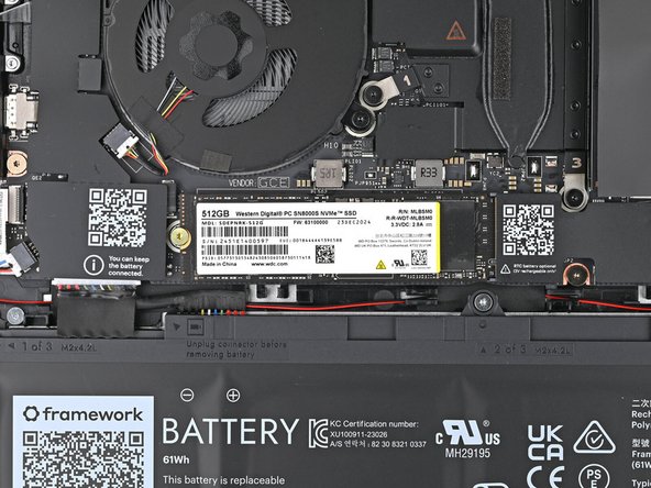
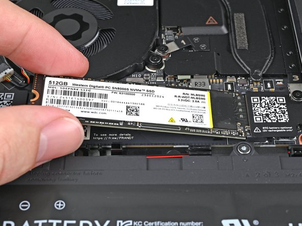
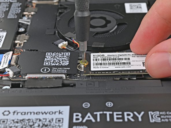
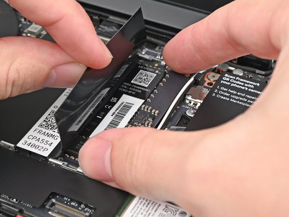
Use your Framework Screwdriver to remove the 3.0 mm‑long T5 Torx screw securing the SSD.
-
The SSD might pop up at a shallow angle when you remove the screw.
-
-
-
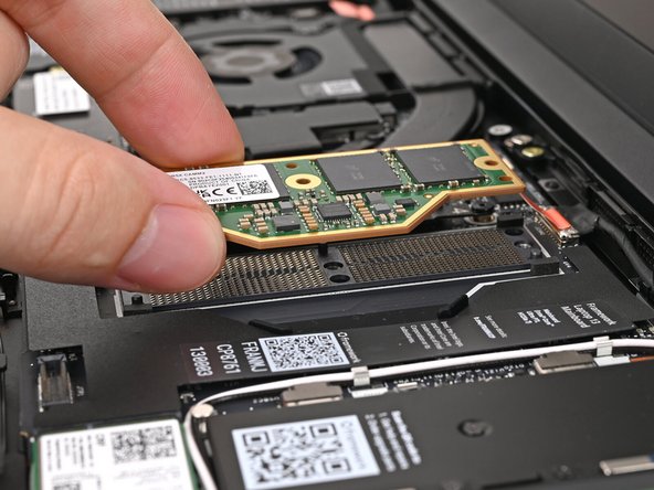
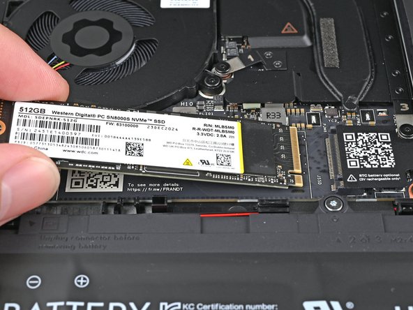
Grip the end of the SSD with the screw hole and slide it out of its socket.
-
Remove the SSD.
-
-
-
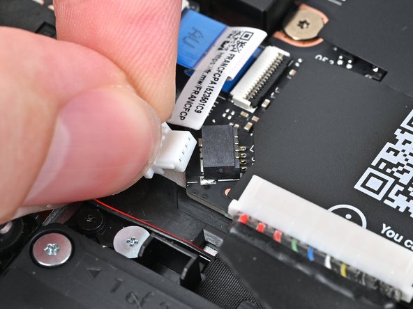
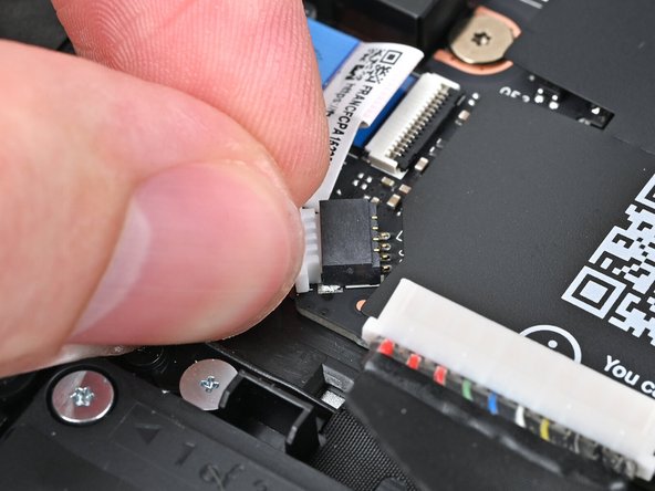
Use your fingers to grip the edges of the speaker cable connector.
-
Pull the connector straight out of its socket to disconnect it.
-
-
-
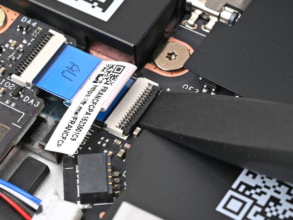
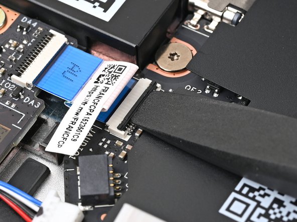
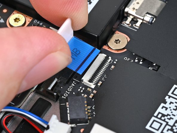
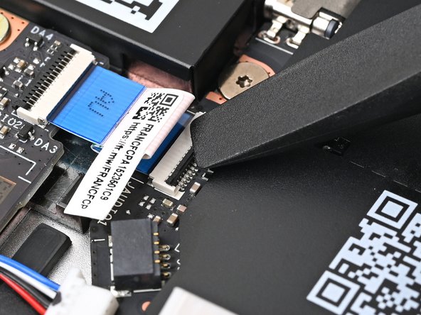
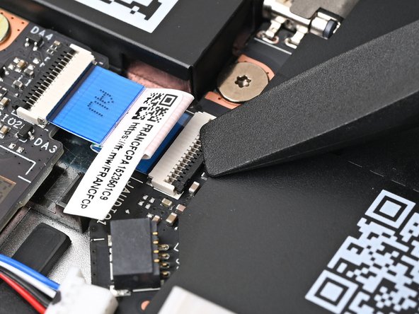
Use the flat end of your Framework Screwdriver, or a clean fingernail, to lift up the locking tab on the Audio Board ZIF connector on the Mainboard.
-
-
-
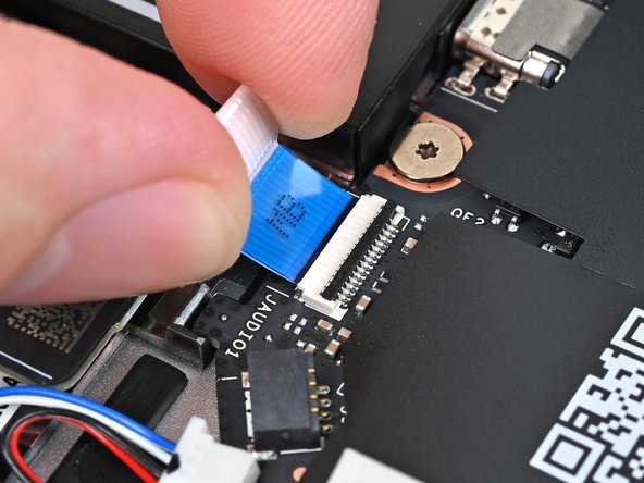
Use your fingers to lightly grip the Audio Board cable and slide it straight out of its socket.
-
-
-
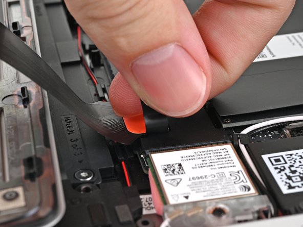
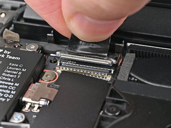
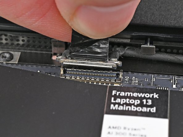
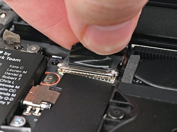
Grip the eDP Cable connector by its pull tab and lift up to disconnect it.
-
-
-
Repeat the previous step for the Webcam Cable connector.
-
-
-
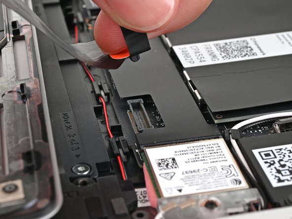
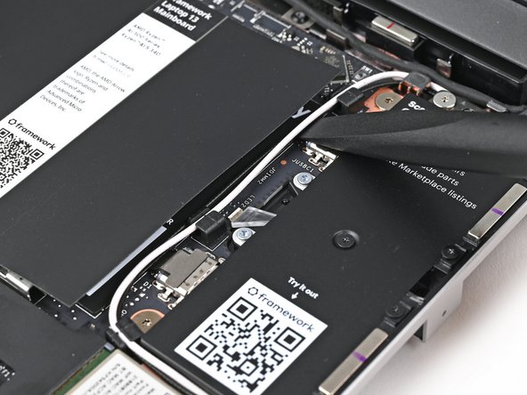
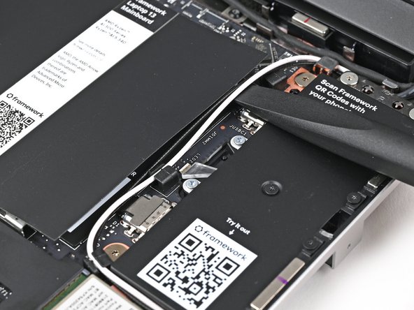
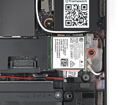
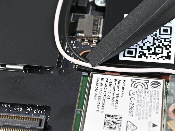
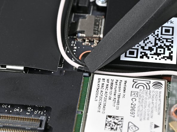
Use the flat end of the Framework Screwdriver to lift the two antenna cables out of their rubber clips on the Mainboard.
-
-
-
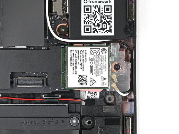
Use your Framework Screwdriver to loosen the captive T5 Torx screw securing Wi-Fi module.
-
The module might pop up at a shallow angle when you loosen the screw.
-
-
-
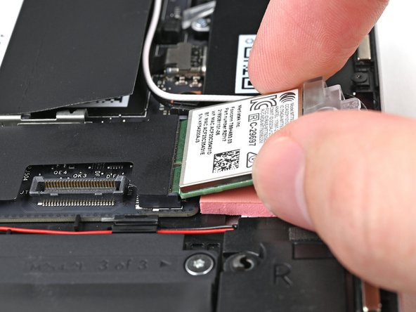
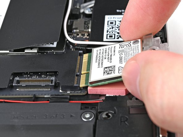
Grip the end of the Wi-Fi module with the screw hole and slide it out of its socket.
-
Don't pull the module too far from its socket, as it's still connected by two cables.
-
Keep the plastic bracket attached to the module to prevent the cables from disconnecting.
-
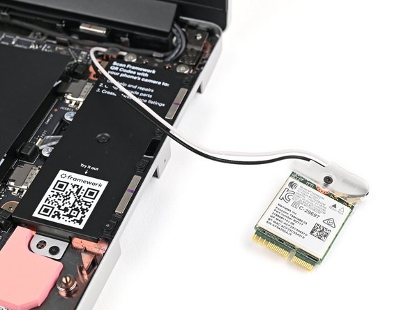
Position the Wi-Fi module to the right of the laptop to keep it out of the way of the Mainboard.
-
-
-
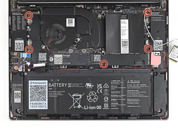
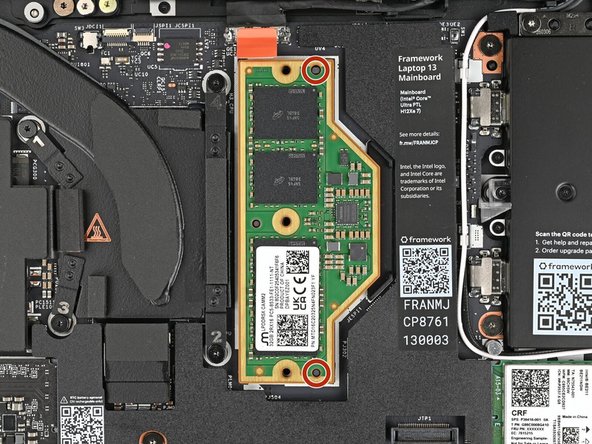
Use your Framework Screwdriver to remove the five 1.5 mm‑long T5 Torx screws securing the Mainboard.
-
Since these screws aren't captive, put them in a safe place.
-
-
-
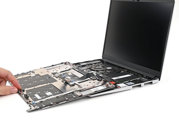
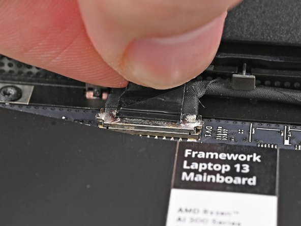
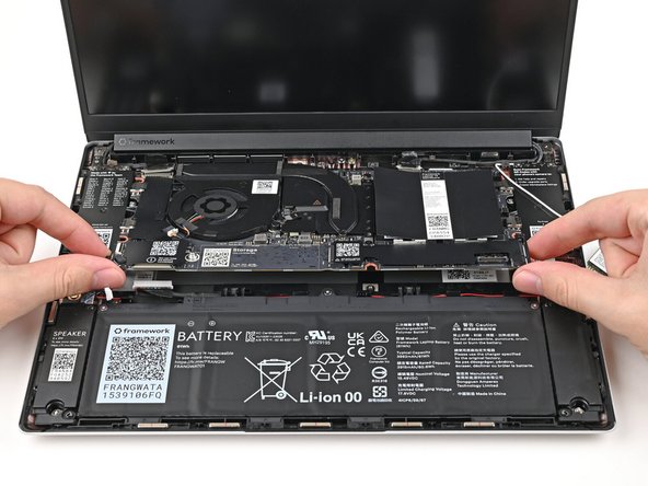
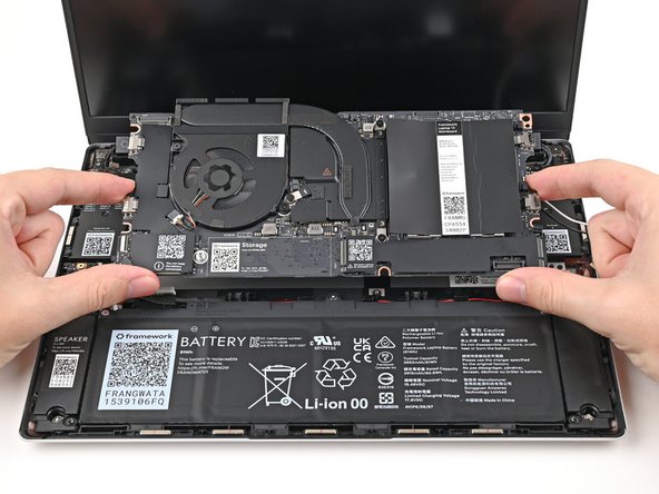
Use your fingers to lift the bottom edge of the Mainboard enough to grip its edges.
-
Lift the Mainboard off its alignment pegs and remove it.
-
-
-
Congratulations on completing disassembly! The remaining steps will show how to reassemble your Framework Laptop.
-
-
-
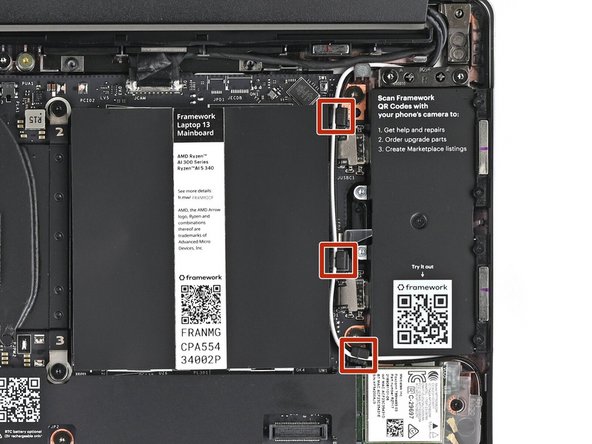
Grab the Mainboard by its edges and place it into the laptop and onto its alignment pegs.
-
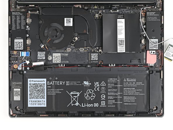
Make sure all of the cables are above the Mainboard before continuing. Refer to this image for where the cables are located.
-
-
-
Use your Framework Screwdriver to install the five 1.5 mm‑long T5 Torx screws securing the Mainboard.
-
-
-
Press the Webcam Cable connector straight down into its socket to connect it.
-
-
-
Repeat the previous step for the eDP Cable.
-
-
-
Hold the Wi-Fi module by its edges. Don't touch the gold contacts with your fingers. If you do, wipe the contacts with a clean, lint-free cloth to remove any finger oils.
-
Align the Wi-Fi module's gold contacts and notch with the socket on the Mainboard.
-
Insert the Wi-Fi module into the socket at a shallow angle. The gold contacts should mostly be covered by the socket.
-
The Wi-Fi module fits into the socket in one orientation. If it doesn't fit, try flipping the module.
-
-
-
If the Antenna cables got accidentally disconnected, follow this step to reconnect them. Otherwise, skip this step to continue the guide normally.
-
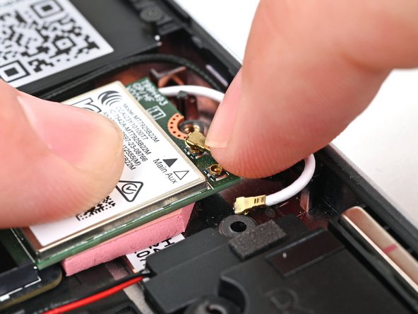
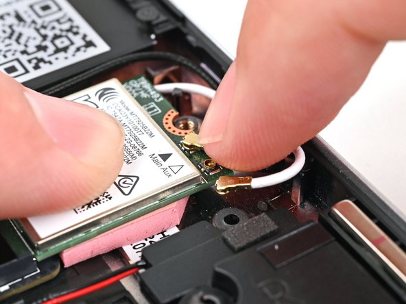
Hold the Wi-Fi Module down with your finger.
-
Position the black Antenna cable connector over the left Wi-Fi module's coaxial socket.
-
If you're unsure which cable goes where, refer to the arrows on the Wi-Fi Module for which color cable matches with its connector.
-
Tweezers can help position the connector.
-
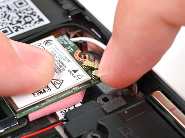
Use your finger to press the connector into place. You should feel a faint click, and the cable will stay attached to the socket by itself.
-
These connectors are very delicate! If the connector doesn't feel like it's clicking in place, reposition the connector and try again.
-
Repeat the procedure with the white Antenna cable.
-
-
-
Use your Framework Screwdriver to tighten the captive T5 Torx screw securing Wi-Fi module.
-
-
-
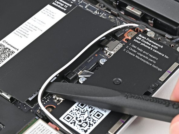
Use the flat end of your Framework Screwdriver to press the two antenna cables into their rubber clips on the Mainboard.
-
-
-
Slide the Audio Board cable straight into its socket.
-
-
-
Use the flat end of your Framework Screwdriver, or a clean fingernail, to press down the locking tab on the Audio Board ZIF connector.
-
-
-
Slide the speaker connector straight into its socket.
-
-
-
Hold the SSD by its edges. Don't touch the gold contacts with your fingers. If you do, wipe the contacts with a clean, lint-free cloth to remove any finger oils.
-
Insert the SSD into the socket at a shallow angle. The gold contacts should mostly be covered by the socket.
-
The SSD fits into the socket in one orientation. If it doesn't feel like it fits, try flipping the module.
-
-
-
While holding the SSD flat to the Mainboard, use your Framework Screwdriver to install the 3.0 mm‑long T5 Torx screw securing the SSD.
-
-
-
If you're installing a LPCAMM2 module, follow the next six steps. If you're installing DDR4 or DDR5 SO-DIMM modules, skip here.
-
Use your Framework Screwdriver to loosen the captive T5 Torx screws securing the LPCAMM2 Memory Cover in reverse order from 3–1.
-
-
-
Lift the LPCAMM2 Memory Cover straight off the memory and remove it.
-
-
-
If present - remove the LPCAMM2 Memory Spacer and recycle it.
-
Avoid touching the Interposer below the Spacer. If the Interposer accidentally shifts, grab it by its edges to place it back into its alignment pegs.
-
Make sure there's no dust or debris on top of the Interposer before continuing.
-
-
-
Place the LPCAMM2 Module on top of the Interposer, making sure it slots into its alignment pegs.
-
-
-
Place the LPCAMM2 Memory Cover on top of the memory, making sure its screws align with the screw holes.
-
The cover should lay flat when aligned properly.
-
-
-
Use your Framework Screwdriver to tighten the captive T5 Torx screws securing the LPCAMM2 Memory Cover in order from 1–3.
-
Make sure the screws are snug enough to create proper contact between the memory and the Mainboard.
-
-
-
Hold the memory module by its edges. Don't touch the gold contacts with your fingers. If you do, wipe the contacts with a clean, lint-free cloth to remove any finger oils.
-
While holding up the black flap covering the left memory module, orient the module with its label facing down and align the gold contacts with the left socket.
-
Insert the contact edge into the socket at a shallow angle. The gold contacts should mostly be covered by the socket.
-
Press the edges of the module down until the side clips lock it in place.
-
-
-
Repeat the previous step for the right socket, except orient the module so its label is facing upward.
-
-
-
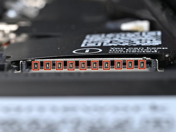
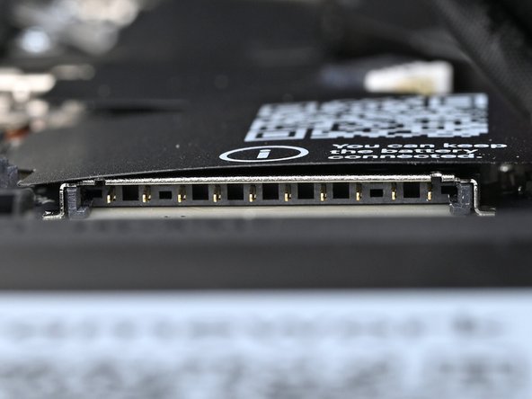
Before continuing, check the pins on the Battery socket and make sure they aren't bent.
-
If any of the pins are bent, reach out to Framework Support.
-
-
-
Use your fingers to align the Battery connector with its socket and slide it straight in to reconnect the Battery.
-
-
-
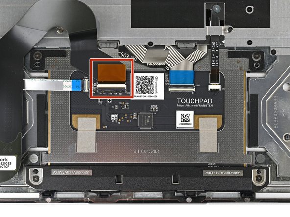
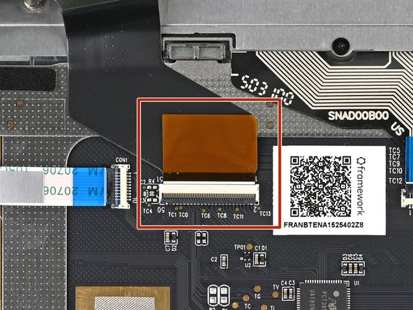
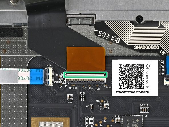
Before continuing, check the Touchpad Cable's ZIF connector located on the back of the Touchpad:
-
Make sure the white line on the cable is parallel to and adjacent with the socket.
-
If the cable isn't inserted far enough, use the flat end of the Framework Screwdriver to flip up the black latch, reposition the cable, and lock the latch.
-
-
-
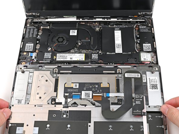
Position the Input Cover, keyboard down, on top of the Laptop so it just covers the battery.
-
This allows the Touchpad Cable to be folded over and reconnected without straining it.
-
-
-
Insert your finger into the Touchpad Cable press connector loop.
-
Align the press connector over its socket and press down with your finger.
-
You should hear it "click" into place. Don't try to force the connector into place. If you're having trouble, reposition it and try again.
-
-
-
Flip the Input Cover over the Laptop and align the bottom edges.
-
-
-
Lay the Input Cover over the laptop and let the magnets snap it into place.
-
The covers are magnetic and should fit into one another easily. If you feel any resistance simply lift the Input Cover up and try again.
-
-
-
Use your Framework Screwdriver to tighten the five captive T5 Torx screws securing the Input Cover.
-
Don't overtighten the screws—just make sure they're snug.
-
-
-
Slide an Expansion Card into an Expansion Card slot.
-
You don't need to hold down the release button to install the Expansion Cards—only when you want to remove them.
-
The Expansion Cards should click into place, and the front edge should be flush with the Laptop.
-
For Expansion Card compatibility, check here.
-
Repeat for the remaining Expansion Cards.
-


You finished fixing your Framework Laptop!
Take your e-waste to an R2 or e-Stewards certified recycler.
If you need help, contact Framework support.
You finished fixing your Framework Laptop!
Take your e-waste to an R2 or e-Stewards certified recycler.
If you need help, contact Framework support.
Cancel: I did not complete this guide.
28 other people completed this guide.
11 Comments
Successfully went through that with a gen 13 Intel mainboard.
I use Debian Linux, and I had to reinstall the boot loader so that the new mainboard would accept the previous NVMe as bootable. Not sure whether there is an easier procedure, but I resorted to GrubEFIReinstall - Debian Wiki.
Greate guide overall, I do have one small note to give. When upgrading from the 11th gen Intel mainboard to the 13th gen intel mainboard, there is not a CMOS battery provided with the 13th gen board (from my research that is because it is not needed) but the pictures of the board being upgraded to has the CMOS battery included with it. Since the guide didn't include a note about it, I did move that battery over as well which is tricky to get that battery out of the original board. I would recommend maybe added a new note that the newer gen boards may not have nor need a CMOS battery, so people not out unneeded stress on the old board trying to get the battery out. Keep up the great work.
Matthew Watson - Resolved on Release Reply
Very simple to follow. Great guide that made my replacement simple. My only feedback is to maybe include a good picture of the display cable. Mine came out a bit further from the display and it was tricky figuring out where it went back in. Maybe a step after 28 showing the display bezel going back on would be a good place for that.
Nathan Michalik - Resolved on Release Reply
Is there a reason the battery is plugged in first upon reassembly? Usually the battery should be plugged in last in my experience.
Nope, no good reason. The assembly can be done safely with the battery connected, but there is also no reason for it to be first.
This guide is great. I’ve replaced the input board on a Macbook Pro (successfully I might add), and I can’t even imagine what replacing the mainboard on one must be like. This is nuthin’ - it took me about 30 minutes because I like to be super careful but it’s really easy.
I haven’t got a framework laptop yet but I wanted to check how thorough the guides for replacing parts are and after reading this one I can say I am very impressed and relieved! My fear when messing with electronics is that it won’t be easy to put it back together but this gives you all the steps from start to finish. They don’t assume that you just know (or should know) stuff which is great. It feels me with confidence that replacing something on my own will be just a matter of “oh how long will that take me” and not “oh I am not sure I can do it without breaking it“. Really looking forward to buying one when it is available in the UK.
Konstantinos Efthymiou - Resolved on Release Reply