
Introduction
This guide will assist you with replacing the Liquid Metal on your Framework 16 with PTM 7958.
Tools
Parts
No parts specified.
-
-
Before beginning, make sure to shut down your Framework Laptop.
-
If the system is still powered on, you will see the chassis intrusion lights flashing red and blue when the Touchpad and Input Modules are removed.
-
-
-
To remove the Expansion Cards, first turn the Framework Laptop 16 over and open the Expansion Card Latches.
-
With the latches open the Expansion Cards should slide right out.
-
If the latches are open and the cards feel stuck, you can use the spudger end of your Framework Screwdriver to push them out.
-
-
-
In order to remove the Input Modules from the Framework Laptop 16, begin by opening the Input Deck Latches on each side of the Laptop.
-
When the latches are open you can see the red printed on the latch.
-
-
-
To remove the Touchpad Spacers, slide them down and then they will lift away easily.
-
If there is resistance, make sure that the Input Deck Latches are open (see previous step).
-
-
-
After removing the Spacers, the Touchpad module can be removed in the same way. Gently slide it downwards from both sides and then lift away as shown.
-
-
-
To remove the Keyboard lift from the bottom using the pull tabs, and once lifted up the Keyboard module should lift out without resistance.
-
If your pull tabs are no longer attached, you can carefully use the spudger side of the Framework Screwdriver to lift the module away.
-
-
-
Remove your Input Modules or Spacers in the same way as the Keyboard, lifting from the bottom using the pull tabs as shown.
-
-
-
Depending on if you have the Expansion Bay Shell or Graphics Module installed, you will have to remove it first. Follow the guide below to remove the specific module you have installed. Once removed, come back to this guide and continue to the next step.
-
To remove the "Expansion Bay Shell" from your Framework 16, please follow this guide: Remove Expansion Bay Shell
-
To remove the "Graphics Module" from your Framework 16, please follow this guide: Remove Graphics Module
-
-
-
Using the spudger side of your Framework Screwdriver, flip open the latch securing the Fingerprint Reader cable in place.
-
Using the pull tab, gently pull the Fingerprint Reader cable out of the socket on the Mainboard.
-
-
-
Since the Ventilation Plate is held in place by the Mid Plate and the module installed in the Expansion Bay, with both of these removed, you can now lift it away from the Bottom Cover.
-
As you lift the Ventilation Plate away, peel the light adhesive holding the Fingerprint Reader Cable onto the Bottom Cover as shown.
-
-
-
Loosen the 3 fasteners, note that these are captive fasteners that will remain attached to the Battery.
-
Lift the pull tab up to disconnect the Battery then lift it out to remove it from the Bottom Cover.
-
-
-
Disconnect the Speaker cable from the Mainboard by pulling directly up using the pull tab as shown.
-
-
-
At the top of the Mainboard are three connectors to remove, from right to left these are the eDP (Display) cable, the Webcam Cable and the WiFi.
-
Disconnect the eDP and Webcam cables by pulling directly up on the pull tabs and unroute the cables slightly from their guides as shown to keep them out of the way of the Mainboard.
-
Remove the WiFi Bracket using the Torx T5 bit on your Framework Screwdriver and remove the WiFi Card as shown.
-
We recommend for this guide to keep the WiFi Module attached to the antenna cables as these can be difficult to reattach.
-
-
-
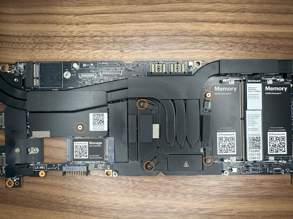
Using the Torx T5 bit in the Framework Screwdriver remove the six fasteners shown.
-
Note that one of the fasteners is under the Interposer Door.
-
-
-
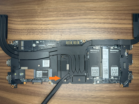
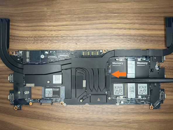
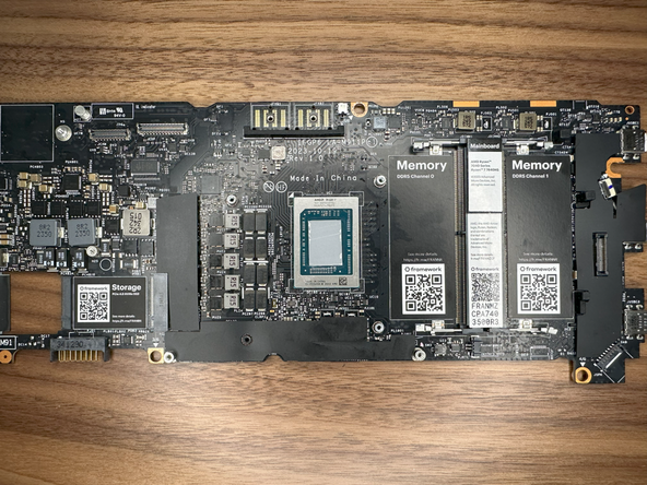
Lifting from the edges of the board and heatpipes as shown lift the Mainboard out of the Bottom Cover as shown.
-
There should be little resistance so if the Mainboard feels stuck, make sure all six fasteners were removed in the previous step.
-
-
-
Unscrew CPU Heatsink screws in order as labeled 1-4.
-
These screws are captive so you do not need to worry about losing them.
-
Unscrew the 5th screw to the left of the CPU Heatsink on the metal plate.
-
-
-
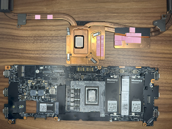
Using the spudger side of the Framework screwdriver, pry the CPU Heatsink away from the mainboard.
-
Work around the sides slowly prying it away.
-
Make sure in this process you do not bend one of the Heatsink pipes when using force.
-
-
-
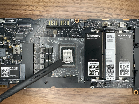
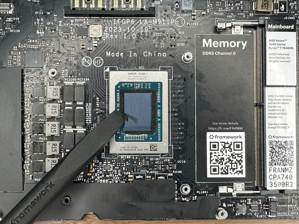
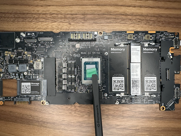
Using the spudger, remove the liquid metal from the CPU die.
-
Once mostly removed use Isopropyl Alcohol to clean the CPU die further and remove any remaining bits of the Liquid Metal.
-
Verify all parts of the Liquid Metal are removed, make sure the CPU die is clean and reflective.
-
Make sure there are no remaining parts of Liquid Metal in the system. If parts remain in incorrect spots, it can cause a short in the system.
-
-
-
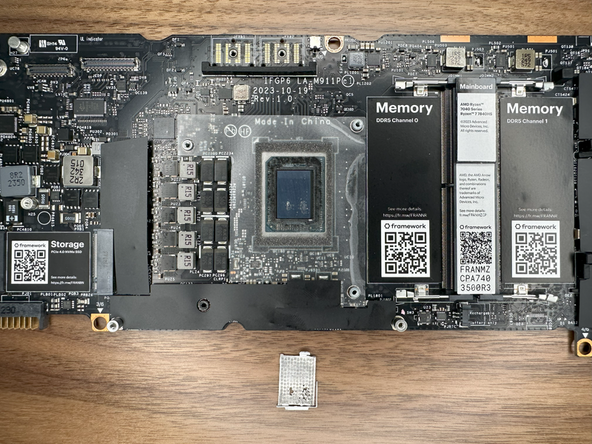
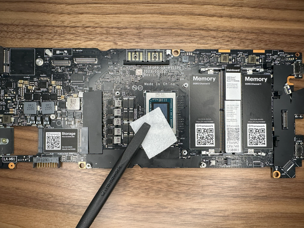
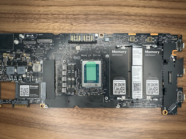
Gently peel away the clear protective tape surrounding the CPU.
-
Remove the black Sponge surrounding the CPU Die.
-
Do a final wipe down with Isopropyl Alcohol to remove any remaining bits of Liquid Metal, Sponge, or Residue.
-
-
-
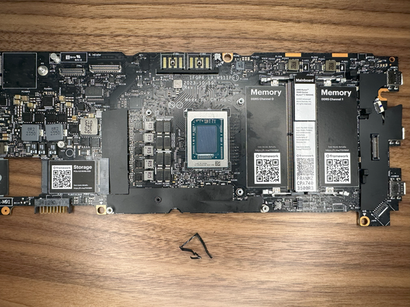
Make sure that your CPU Die and mainboard look like this with the Liquid Metal and Black Sponge removed.
-
-
-
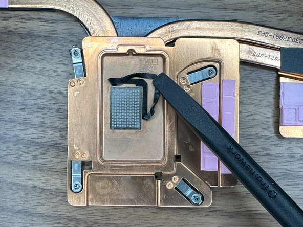
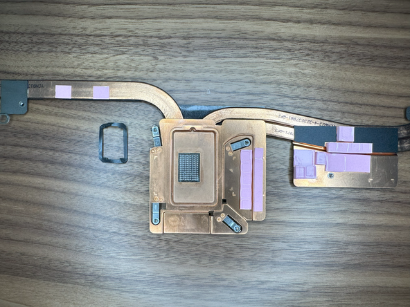
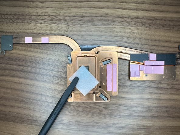
Using the Spudger of the Framework Screwdriver, remove the sponge on the Heatsink.
-
Using the Isopropyl Alcohol, clean off the sponge residue and wipe down the silver honeycomb textured plate.
-
-
-
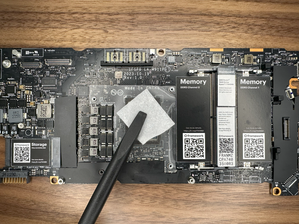
Gently remove the Clear backing on the PTM and apply it to the CPU die.
-
The PTM may be bigger than the CPU die and this is okay. Make sure the PTM is centered and has equal overhang on all sides.
-
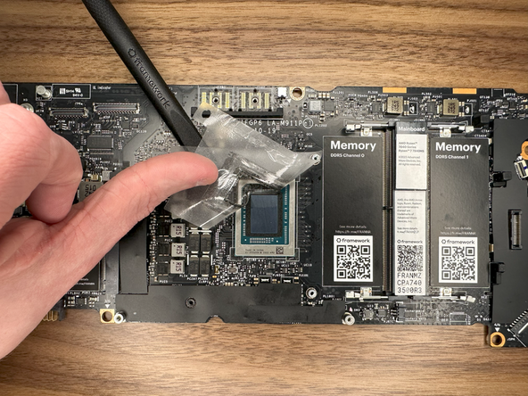
With the PTM on the CPU die, gently press against the Green backing; making sure it is applied successfully.
-
Gently and slowly remove the Green backing from the PTM.
-
PTM should now be successfully applied to the CPU!
-
-
-
Align the CPU Heatsink with the screw standoffs on the Mainboard. Slowly lower it until the Heatsink it touching the Mainboard.
-
Following the numbered order of the screws on the Heatsink, give each 2 turns.
-
Doing this ensures each is tightened with equal pressure and level on the CPU die.
-
Keep following this until all 4 screws are securely tightened.
-
-
-
On the metal plate to the left of the CPU, tighten this screw down.
-
-
-
Male sure that all cables (Speaker, WiFi, eDP, Webcam) are out of the way before installing the Mainboard.
-
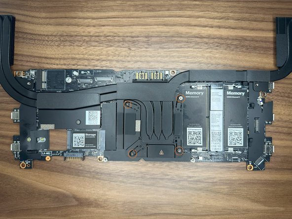
Holding the Mainboard from the edges of the board and the heatpipes as shown, lower it into the Bottom Cover.
-
-
-
Using the Torx T5 bit in the Framework Screwdriver install the six Mainboard fasteners, noting that one of them is under the Interposer Door.
-
-
-
Starting from left to right install the WiFi Module, the Webcam cable and the eDP cable.
-
Plug in the WiFi Module, route the antenna cables through the channel above the Mainboard and around the metal post on the Mainboard as shown, and then secure the WiFi Bracket using the Torx T5 bit on your Framework Screwdriver.
-
Connect the eDP and Webcam cables by lining them up with the socket on the Mainboard and pushing gently down.
-
-
-
Place the Ventilation Plate into place as shown, the holes for fasteners will align with the bottom cover.
-
Gently press down the Finger Print Reader cable to stick it to the Bottom Cover.
-
-
-
With the latch on the Mainboard open, connect the Fingerprint Reader cable to the Mainboard as shown.
-
This is quite a small connector so you may find it easiest to use the tab on the cable to push the cable into place.
-
Once fully inserted, close the latch on the Mainboard to secure the cable in place.
-
-
-
Connect the Speaker cable to the socket on the Mainboard by lining it up to the socket and pressing directly downward as shown.
-
-
-
Depending on if you have the Expansion Bay Shell or Graphics Module, you will have to install it first. Follow the guide below to install the specific module you have. Once installed, come back to this guide and continue to the next step.
-
To install the "Expansion Bay Shell" from your Framework 16, please follow this guide: Install Expansion Bay Shell
-
To install the "Graphics Module" from your Framework 16, please follow this guide: Install Graphics Module (dGPU)
-
-
-
Lower the Battery into place, first aligning the bottom of Battery in the bottom cover as shown, then push down gently to attach the connector to the Mainboard.
-
Tighten the 3 captive fasteners to hold the Battery in place.
-
-
-
Place the Mid Plate onto the system, aligning the holes in the Mid Plate with the two guide posts.
-
These posts are on the left side and the right side, immediately above the speakers on both sides.
-
Take extra time to make sure it's sitting level/ flush.
-
-
-
Using the pull tab, gently press the Mid Plate connector down to connect it to the Mainboard.
-
Carefully align, then firmly press in the mid plate connector cable.
-
-
-
Using the T5 bit in the Framework Screwdriver tighten the Mid Plate fasteners.
-
Before gently tightening the screws, double check that the mid plate is aligned correctly as shown in previous step.
-
These fasteners are labelled 2-17 (since the Mid Plate cable is number 1) and should be tightened in order, starting with 2 and ending with 17.
-
Do not overtighten these fasteners, and we recommend against the use of powered tools for these or any other fasteners on the Framework Laptop 16.
-
-
-
Next install, two Spacer Modules, an LED Matrix, a Numpad, an RGB Macropad, or whichever other combination of two Small or one Medium sized Input Module you have.
-
Slide these in at an angle and lower into place, the same way the Keyboard was installed.
-
Whichever Input modules you chose to install, you should have no empty spaces in the top row before proceeding to the next step.
-
-
-
Please see our guide here on possible Input Module configurations.
-
Holding from the pull tabs at the bottom of the Keyboard module, line it up with the dashed guide lines printed on the Mid Plate. Note that you can align a Keyboard so that it is either along the left edge, the right edge, or centered. With the Keyboard held at a 20 degree angle, slide it up into place.
-
The notches along the top of the Keyboard will fit into the corresponding alignment guides under the Ventilation Plate.
-
Lower the Keyboard gently into place, it should snap in place magnetically and sit flat.
-
Ensure that the pins in the Mid Plate to the left and right of the Input Module Connector align into the corresponding holes in the Keyboard module.
-
-
-
Place the Touchpad Module flat, slightly below the Keyboard as shown.
-
Like the Keyboard, you can confirm it is properly aligned by lining it up to the dashed lines on the Mid Plate.
-
Applying gentle downward pressure to keep the Touchpad module flat, slide it up into place.
-
Remember that the Input Deck Latches should still be open at this point, otherwise the Touchpad Module won't slide on.
-
The Touchpad Module can be installed either directly below the Keyboard or offset by one space to the right. For example, the Keyboard can have the Touchpad below it, or the Keyboard can be left-aligned while the Touchpad is centered.
-
-
-
Just like installing the Touchpad module, place the Touchpad Spacers flat on the Input Deck, slightly below the Keyboard or Spacers above.
-
Applying gentle pressure, slide the Touch Module Spacers into place.
-
With the Touchpad Module Spacers installed there should now be no empty spaces on the Input Deck.
-
-
-
Once all Input Modules are installed, close both Input Deck Latches to secure them in place.
-

Cancel: I did not complete this guide.
10 other people completed this guide.
7 Comments
Just followed this guide successfully. As others have mentioned, it is missing steps for removing the midplate and the battery.
Steele Trotter - Open Reply
Great guide. it is missing the "remove midplate" step, otherwise very complete. I followed all the instructions and now my framework 16 runs like brand new again.
I would also like to see maybe a video demonstration for step 17 just so its easier for people who are doing this the first time.

The guide is still missing the midplate removal step (before step 9, I assume).
Battery disassembly and assembly mentioned in the other comments are already added.
My Framework 16 freq boost improved from 3700 to 4200 mhz under stress test after applying PTM while keeping the same core temp, 99.8C. Even my balanced profile is now at 3800 mhz under stress test, so even that one is better than stock on performance profile. Let's see how long it lasts! :)
Thanks guys for the awesome tutorial! I love it when products get this kind of attention to detail!