Introduction
Use this guide to install the Dual M.2 Adapter in your Framework Laptop 16. This guide also shows how to install SSDs into the Adapter.
Note: installing the Dual M.2 Adapter requires the Graphics Module Interposer, which is optionally bundled with the adapter.
Make sure your BIOS is up to date with the latest version before installing the adapter.
-
-
Unplug all cables and fully shut down your laptop.
-
-
-
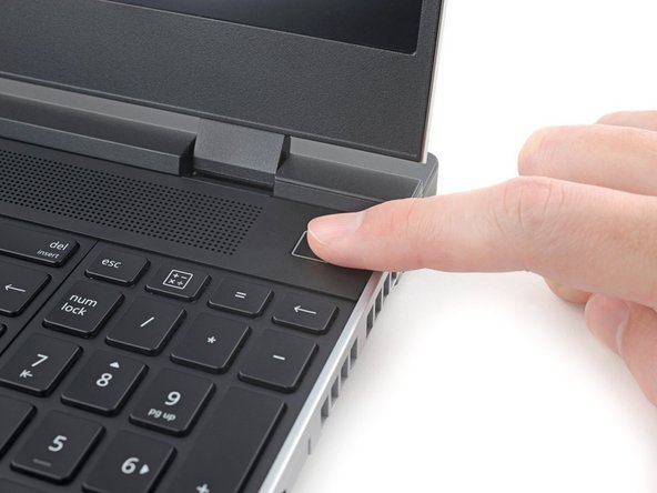
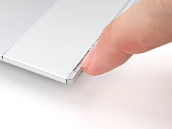
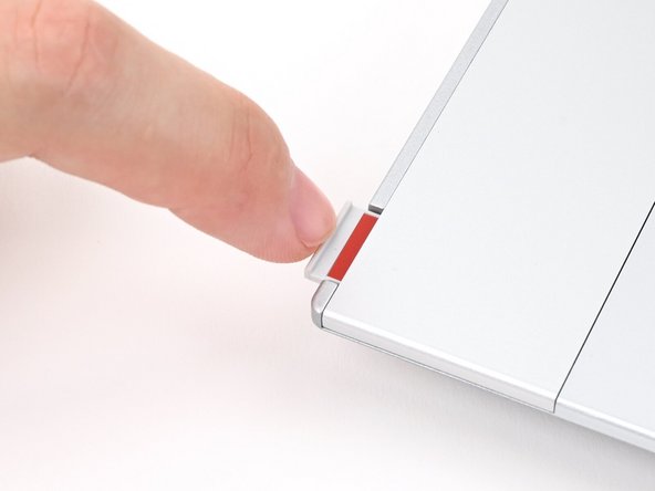
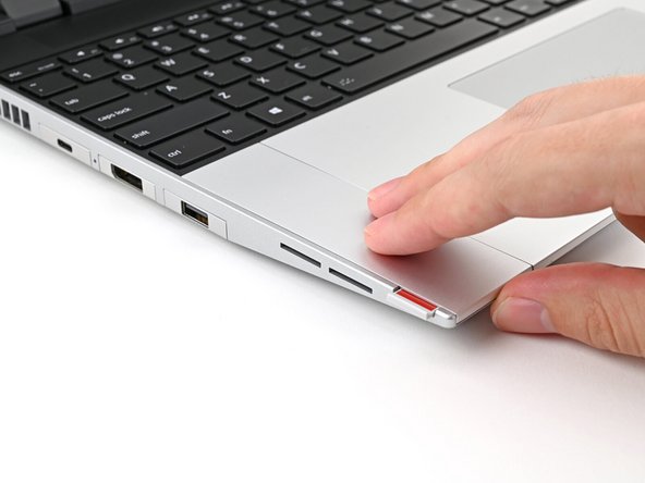
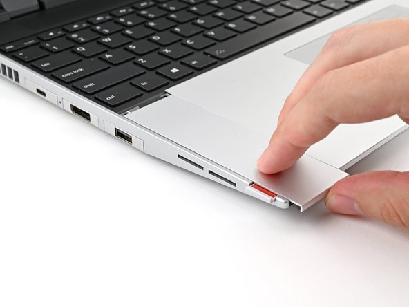
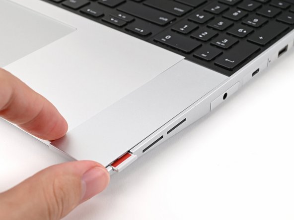
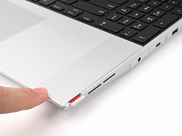
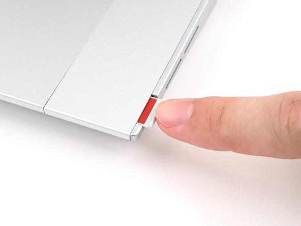
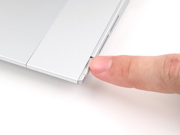
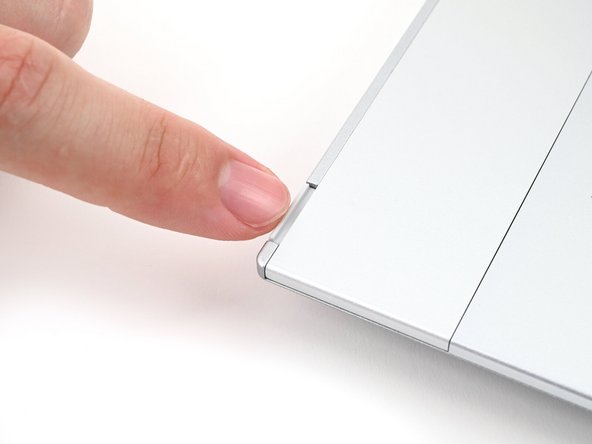
Use your fingernail to pull out the two Input Module latches and unlock them.
-
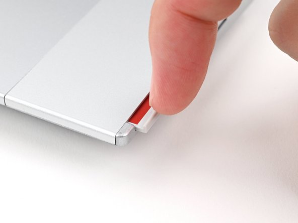
The latch will show red if it's unlocked.
-
-
-
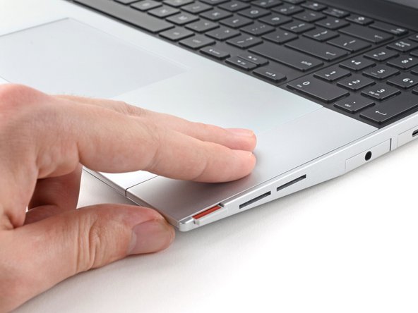
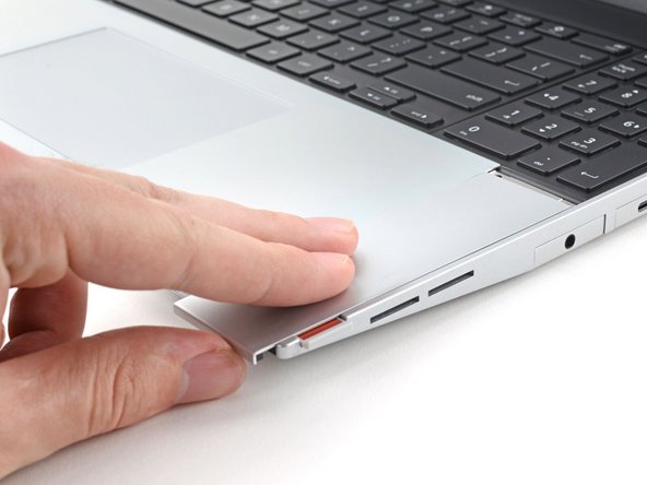
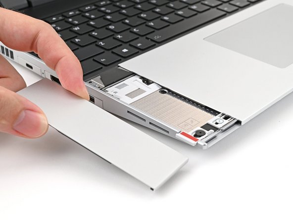
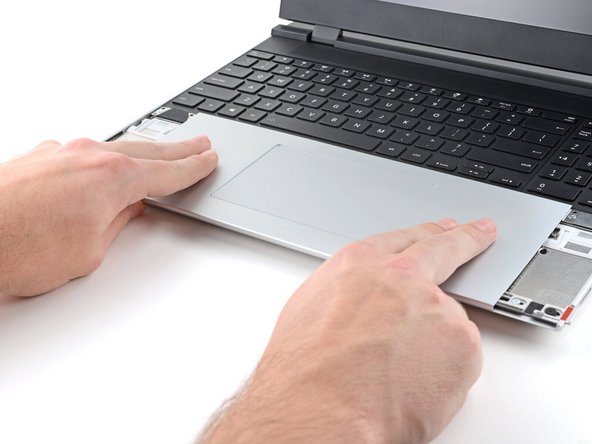
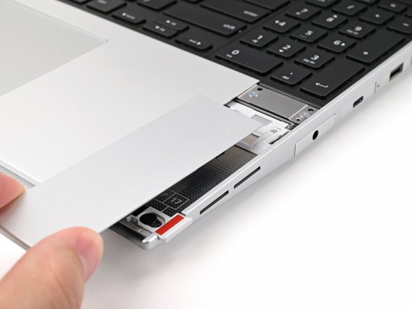
Use your fingers to slide the Touchpad Spacer toward the bottom edge of the laptop and unclip it.
-
If you're having trouble, check if the corresponding Input Module latch is properly unlocked.
-
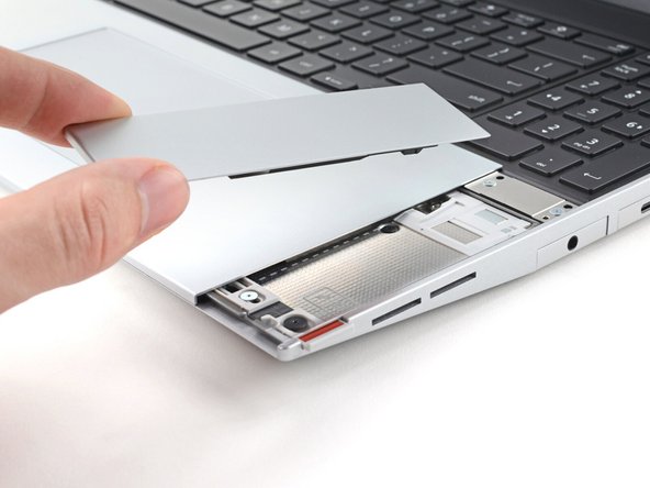
Lift the Touchpad Spacer off the laptop and remove it.
-
-
-
Repeat the same procedure for the other touchpad spacer.
-
-
-
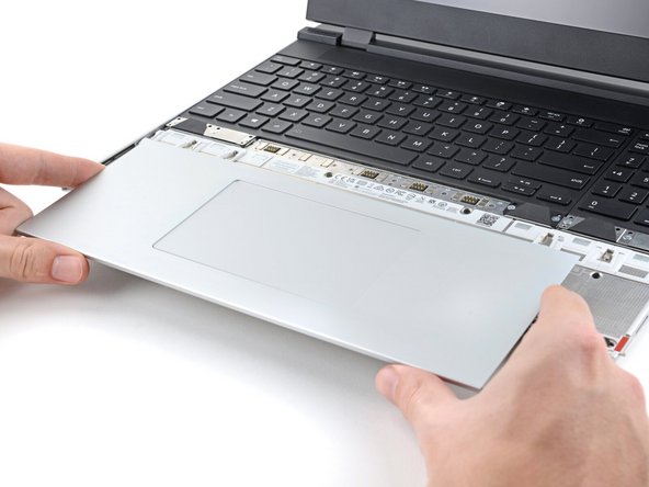
Use your fingers to slide the Touchpad Module toward the bottom edge of the laptop and disconnect it.
-
If you're having trouble, check if the Input Module latches are properly unlocked.
-
Lift the Touchpad Module and remove it.
-
-
-
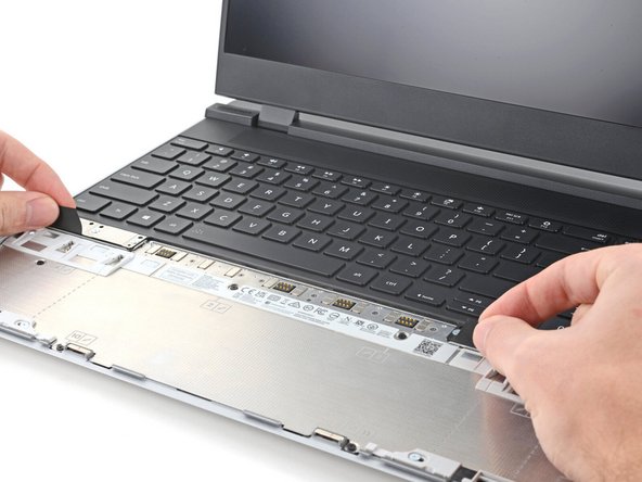
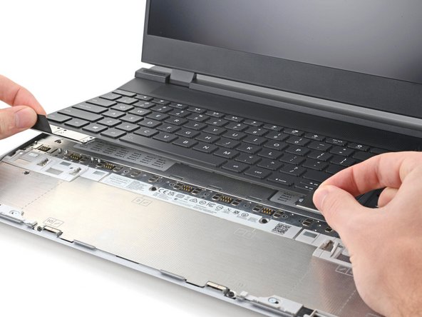
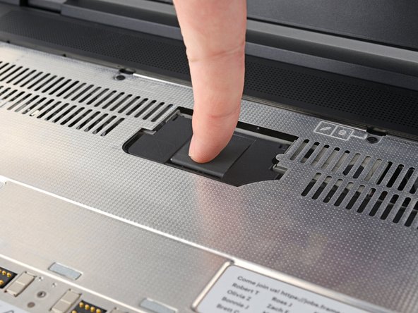
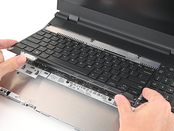
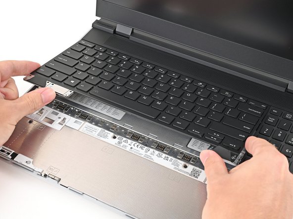
The keyboard is held in place with strong magnets. Apply gradually increasing force to avoid having the keyboard violently eject.
-
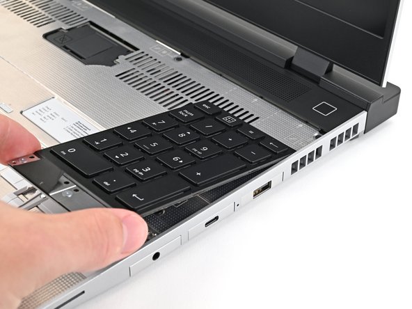
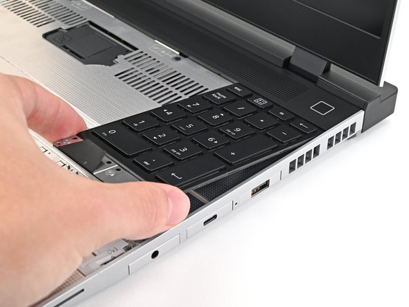
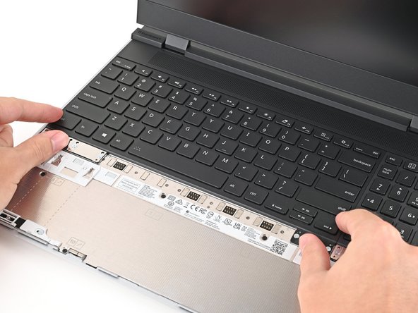
Grip the two pull tabs along the bottom of the keyboard and lift until its magnets release.
-
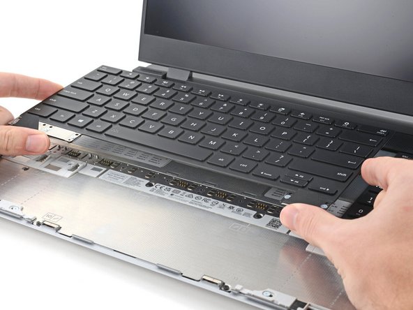
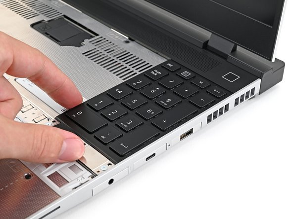
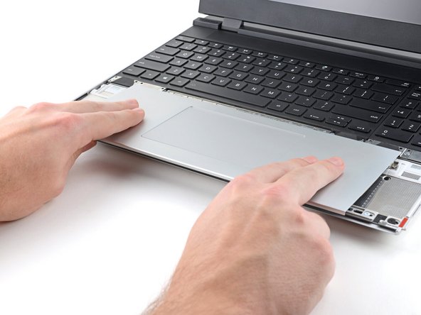
Remove the keyboard.
-
-
-
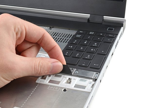
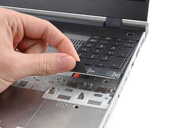
Your Input Module(s) might be different, but the procedure to remove them is the same.
-
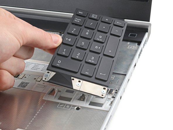
Grip the pull tab at the bottom of the Input Module and lift until its magnets release.
-
Remove the Input Module.
-
Repeat for any remaining Input Modules.
-
-
-
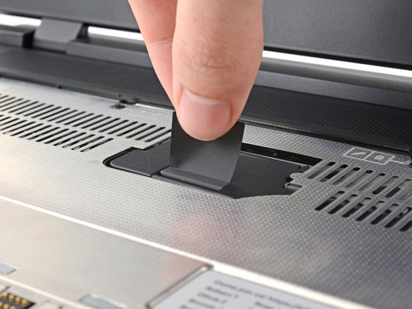
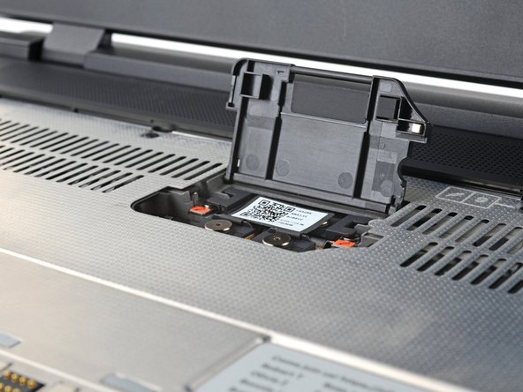
Lift the interposer door by its black pull tab and let it rest upright.
-
-
-
If you have the Graphics Module installed, your interposer will have four screws. If you have the Expansion Bay Shell installed, you'll have three screws instead.
-
If you have the Graphics Module, use your Framework Screwdriver to loosen the four captive T5 Torx screws securing the interposer.
-
If you have the Expansion Bay Shell, use your Framework Screwdriver to loosen the three captive T5 Torx screws securing the interposer.
-
-
-
Lift the interposer by its pull tab and remove it.
-
-
-
Use your Framework Screwdriver to loosen the two captive T5 Torx screws securing the Expansion Bay Module.
-
Close the interposer door before continuing.
-
-
-
Close your laptop and flip it over.
-
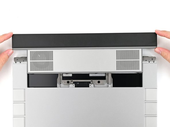
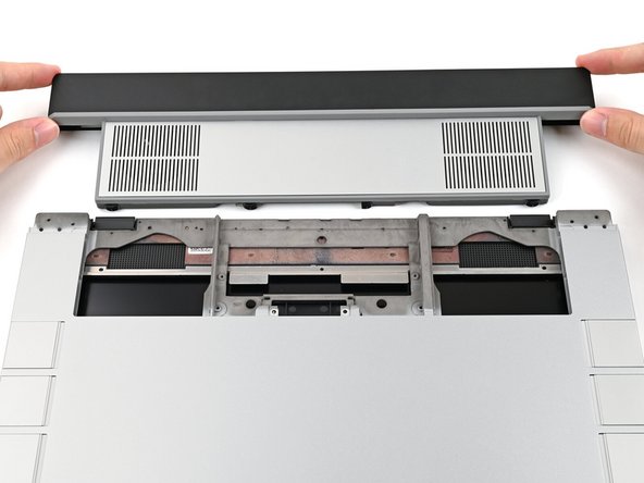
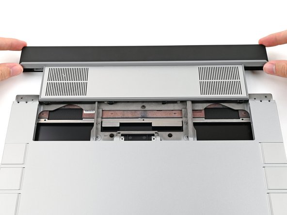
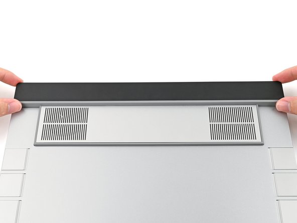
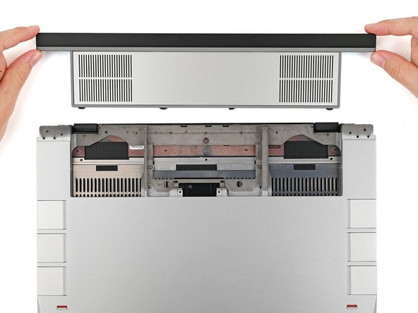
Slide the Expansion Bay Module out of the laptop and remove it.
-
The module should slide out easily. If you feel any resistance, check that the screws holding it in place are fully loosened.
-
-
-
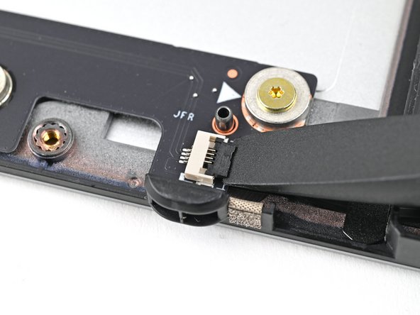
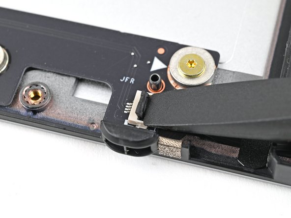
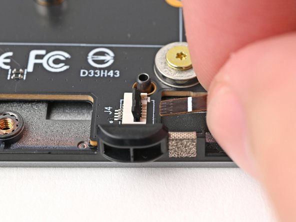
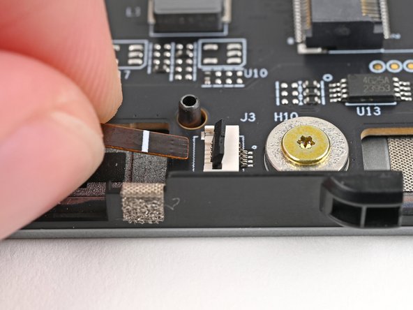
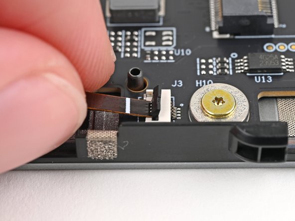
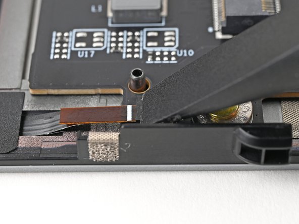
Use the flat end of your Framework Screwdriver, or a clean fingernail, to lift up and release the locking tab on the right fan ZIF connector.
-
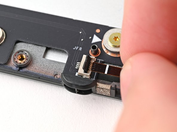
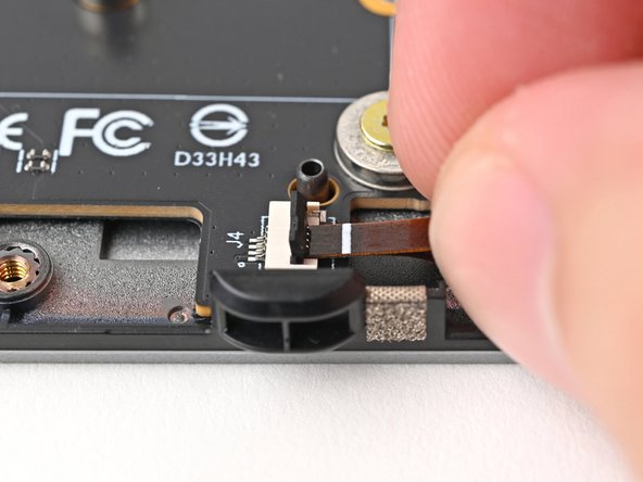
Use your fingers to grip the brown pull tab and slide the fan cable straight out of its socket.
-
-
-
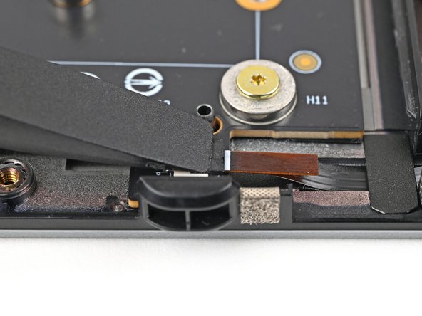
Repeat the previous step to disconnect the left fan cable.
-
-
-
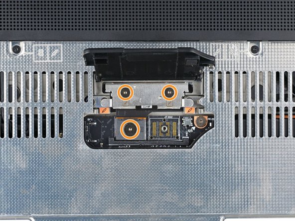
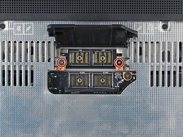
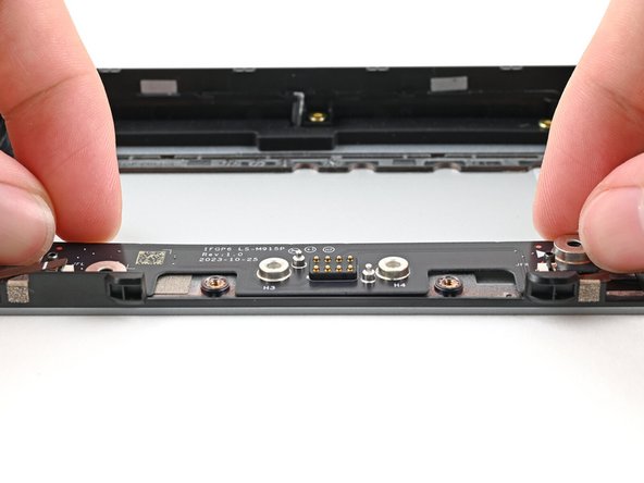
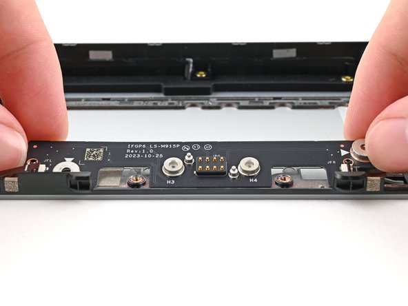
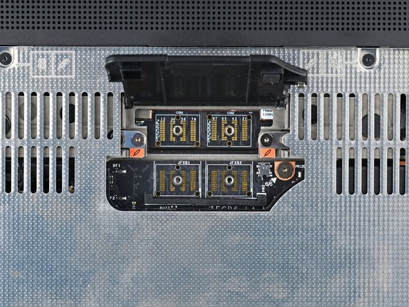
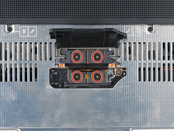
Use your Framework Screwdriver to remove the two 3.6 mm‑long screws securing the Expansion Bay Shell Fan Board.
-
-
-
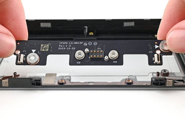
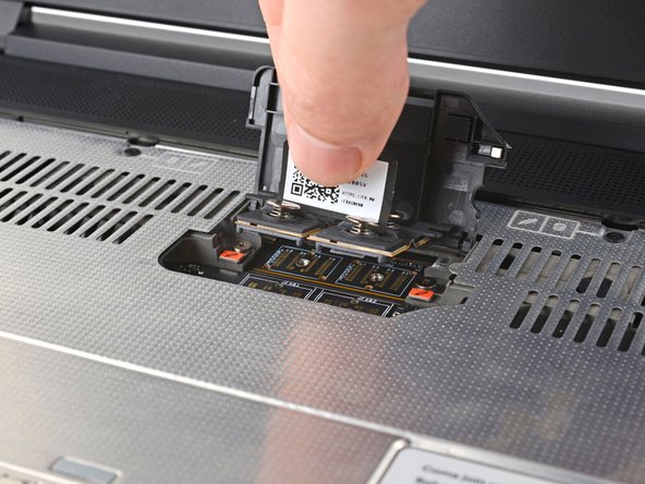
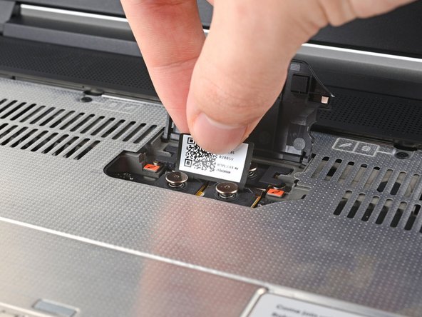
Use your fingers to lift the board straight off its alignment pegs on Expansion Bay Shell and remove it.
-
-
-
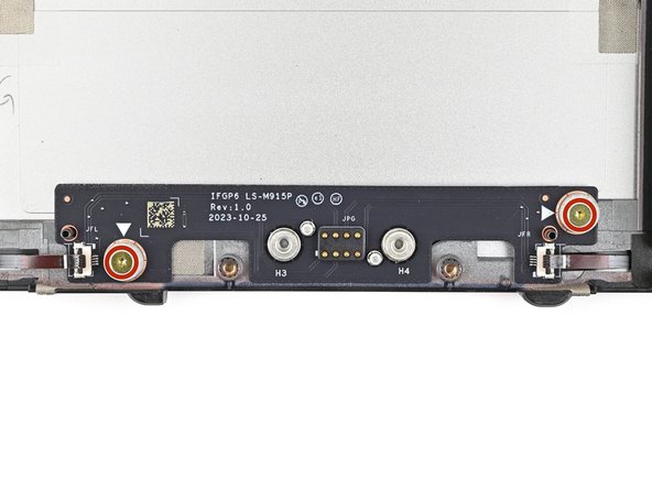
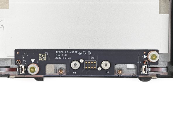
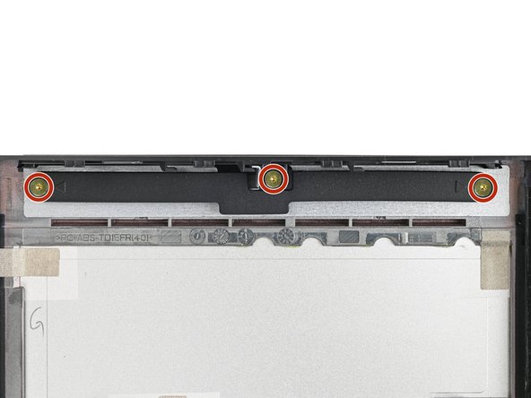
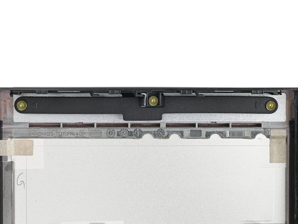
Use your Framework Screwdriver to remove the three 3.6 mm‑long screws securing the rubber spacer.
-
Hold on to these screws—you'll use them to install the Dual M.2 Adapter.
-
-
-
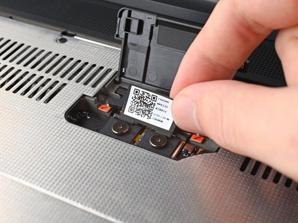
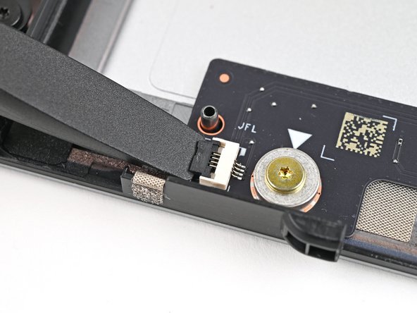
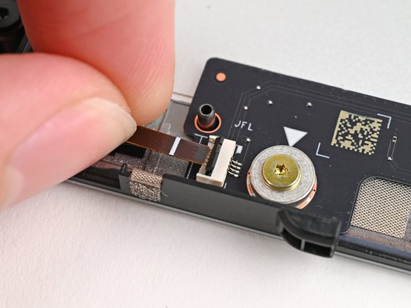
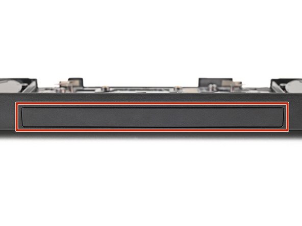
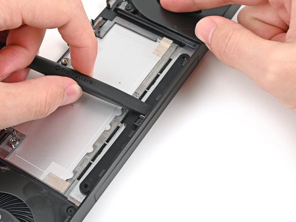
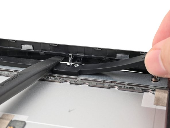
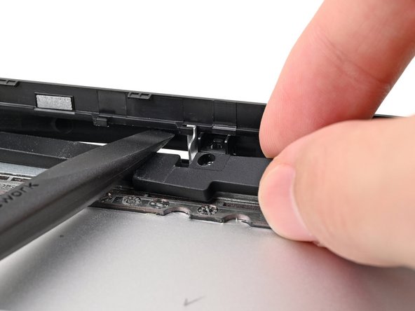
While holding the Expansion Bay Shell down, use the flat end of your Framework Screwdriver to push the plastic strip near the rubber spacer outwards.
-
-
-
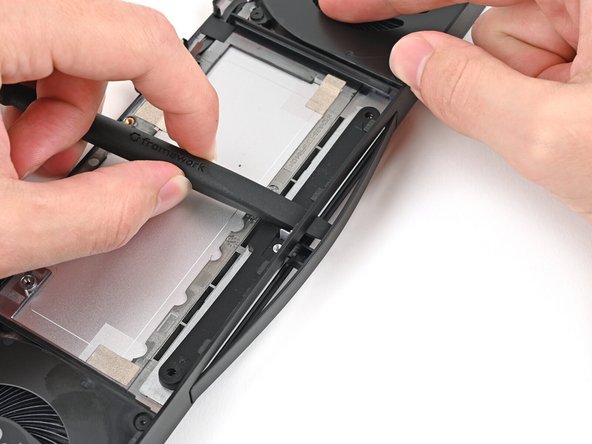
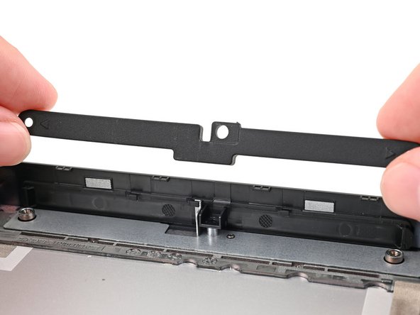
While keeping the plastic strip bent, lift the rubber spacer out of its screw posts and remove it.
-
-
-
Congratulations on completing disassembly! The remaining steps will show how to reassemble your Framework Laptop.
-
-
-
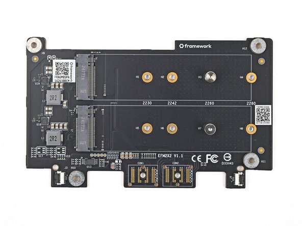
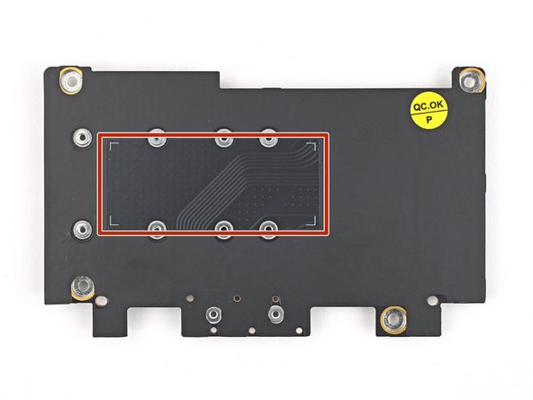
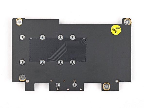
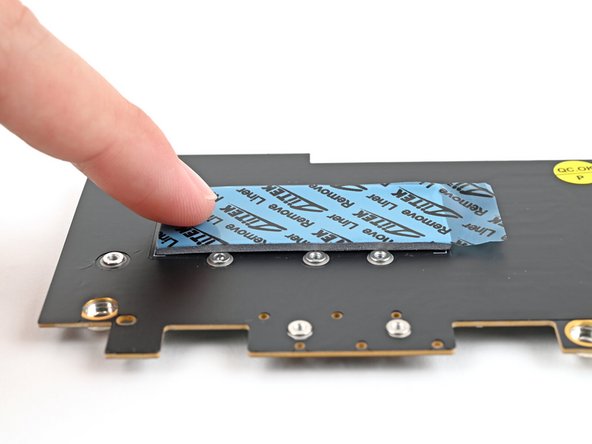
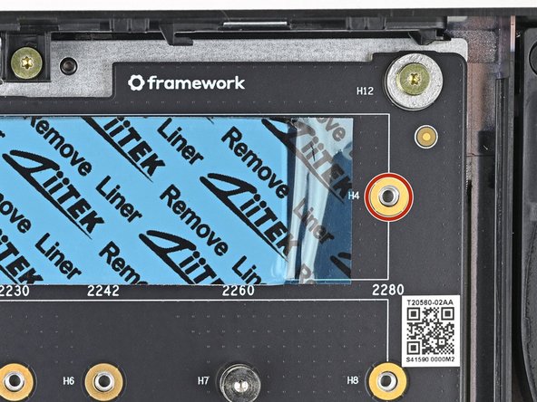
Flip over your Dual M.2 Adapter and locate the marked section where you'll place the 1.75 mm thermal pad.
-
When placing the thermal pad, make sure you don't cover the screw holes.
-
-
-
Once you place the thermal pad, it's difficult to peel it off and move it without damaging it. Take your time and work slowly to ensure it's aligned properly.
-
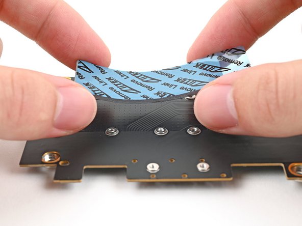
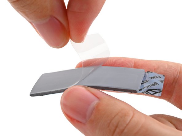
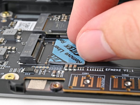
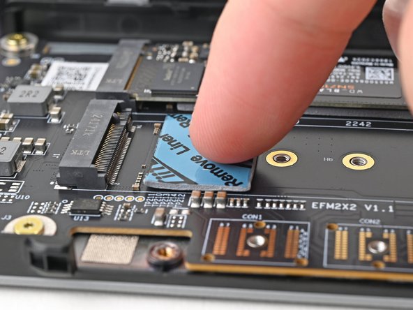
Remove the clear liner from the thermal pad labeled 1.75 mm to expose one side of it.
-
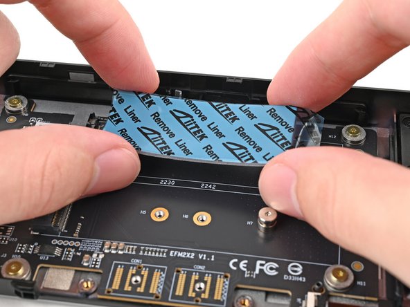
Place the thermal pad over its spot on the back of the adapter.
-
If you have trouble handling your thermal pad, you can store it in your fridge for a few minutes to make it more rigid.
-
-
-
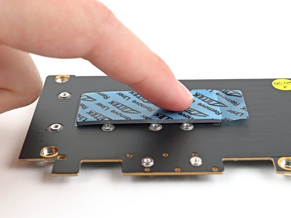
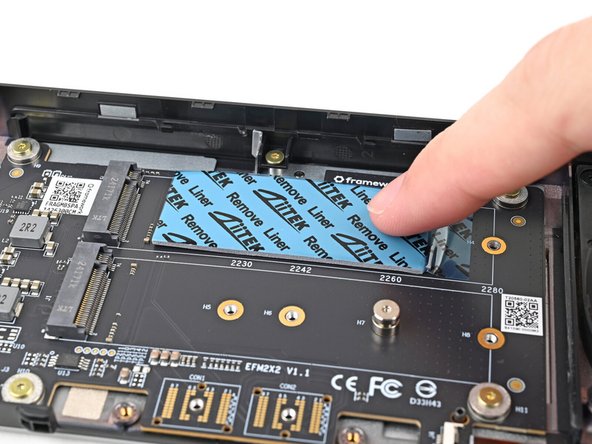
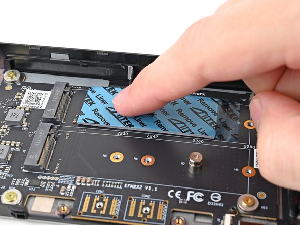
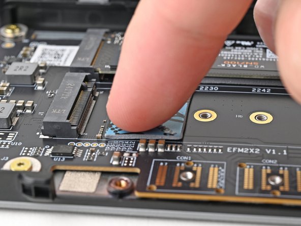
Use your finger to gently press the thermal pad onto the adapter.
-
-
-
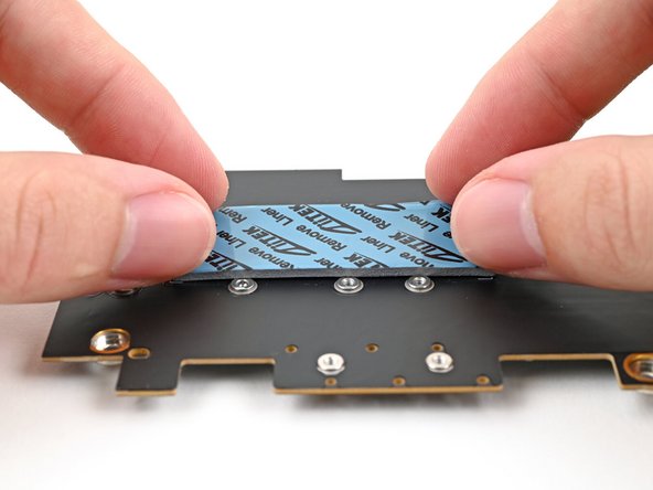
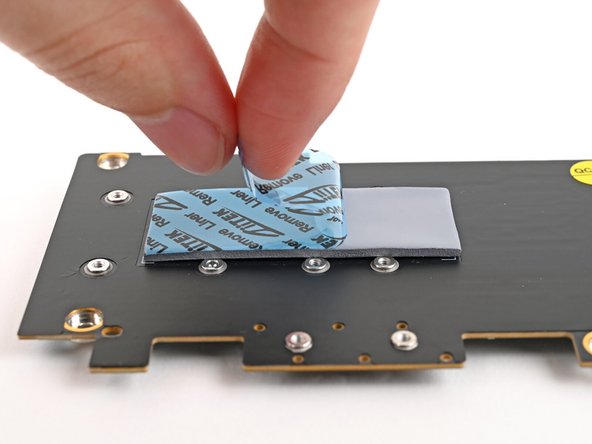
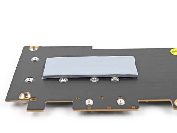
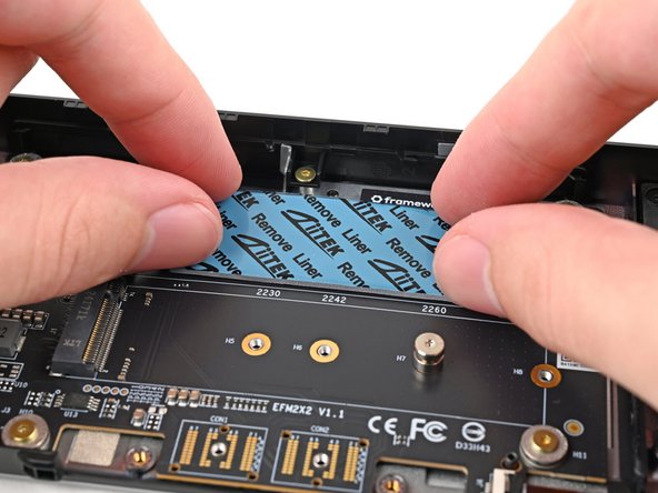
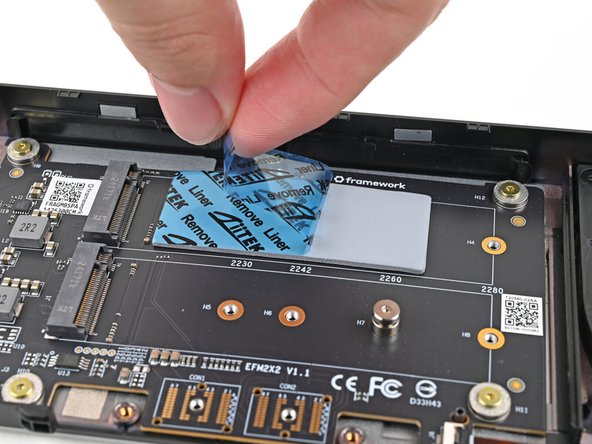
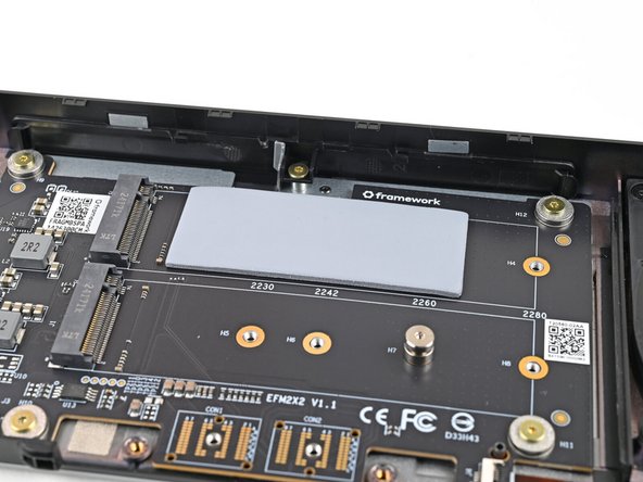
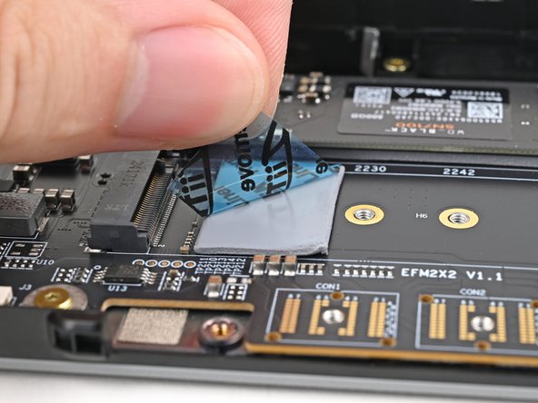
Remove the blue liner to expose its top side.
-
-
-
Once you place the Dual M.2 Adapter, it's difficult to remove it without damaging the thermal pad. Take your time and work slowly to ensure the adapter is aligned properly.
-
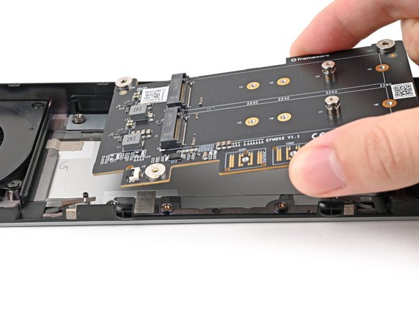
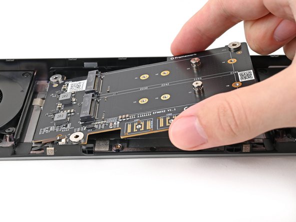
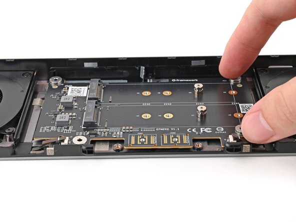
Flip over the adapter and place it into its spot in the Expansion Bay Shell, making sure it slots into its alignment pegs.
-
Before continuing, make sure the fan cables aren't trapped under the adapter.
-
-
-
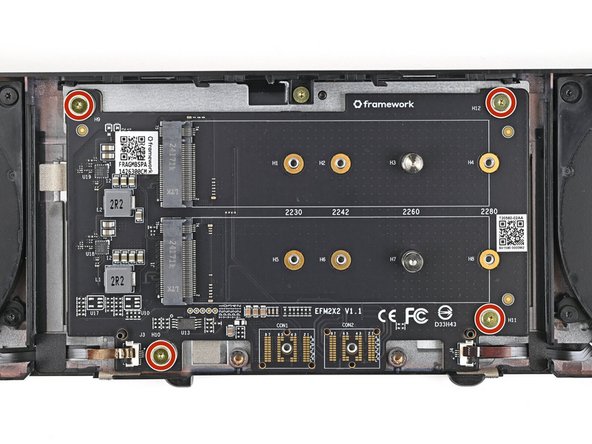
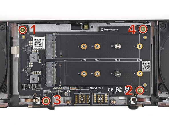
Use your Framework Screwdriver to partially install the four 3.6 mm‑long screws securing the Dual M.2 Adapter—only screw them in a few turns.
-
Tighten the four screws in an "X" pattern starting with the top left screw.
-
Only tighten the screws a few turns at a time to evenly compress the thermal pad.
-
In order: top left → bottom right → bottom left → top right
-
-
-
Use your fingers to grip the brown pull tab and slide the right fan cable straight into its socket.
-
Use the flat end of your Framework Screwdriver, or a clean fingernail, to press down the locking tab on the right fan ZIF connector.
-
-
-
Repeat the previous step for the left fan.
-
-
-
Depending on the size of your SSD, you may need to change the screw position and cut down the included thermal pad to fit the SSD.
-
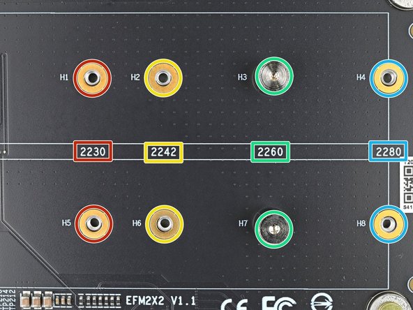
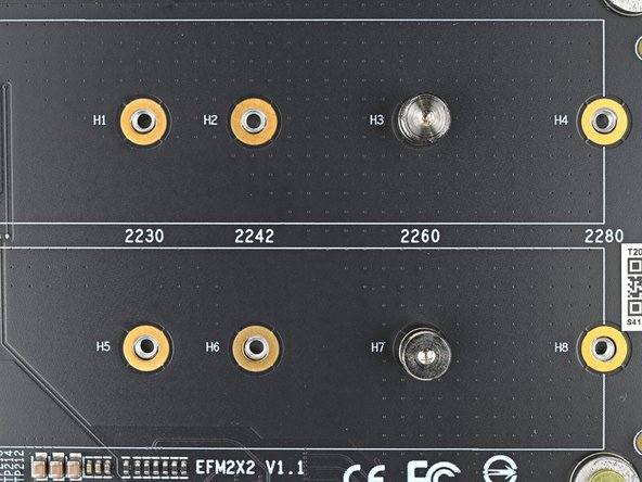
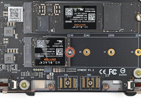
Refer to the markings on the adapter to figure out where your SSD will go:
-
2230 SSDs → H1 or H5
-
2242 SSDs → H2 or H6
-
2260 SSDs → H3 or H7
-
2280 SSDs → H4 or H8
-
-
-
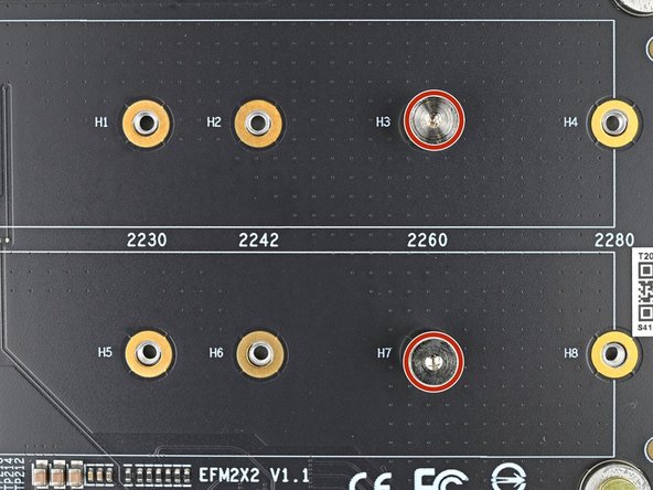
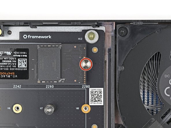
Use your Framework Screwdriver to remove one or both of the 6.7 mm‑long T5 Torx SSD screws, depending on how many SSDs you're installing.
-
-
-
The next six steps will show how to install a 2280 SSD. If you're installing anything smaller, skip to this step.
-
If you're installing a single‑sided SSD (chips on only one side), grab the 2.25 mm thermal pad.
-
If you're installing a double‑sided SSD (chips on both sides), grab the 1.25 mm thermal pad.
-
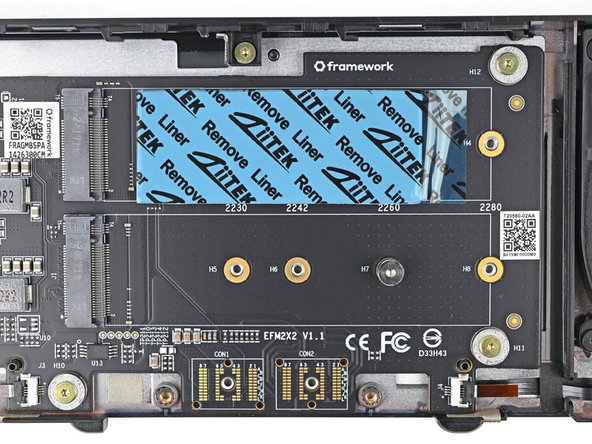
Without removing any liners, place the thermal pad over the slot where you want to install your SSD.
-
Orient the thermal pad so it sits between the small components next to the SSD's socket and the screw hole—including the gold ring around it.
-
When you're confident in how your thermal pad should be oriented, remove it and continue to the next step.
-
-
-
Remove the clear liner from the thermal pad to expose one side of it.
-
Place the thermal pad over its spot on the adapter.
-
-
-
Use your finger to gently press the thermal pad onto the adapter.
-
-
-
Remove the blue liner to expose its top side.
-
-
-
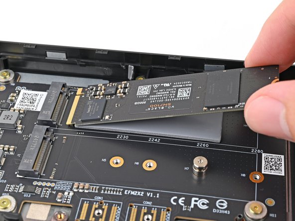
Hold the SSD by its edges. Don't touch the gold contacts with your fingers. If you do, wipe the contacts with a clean, lint-free cloth to remove any finger oils.
-
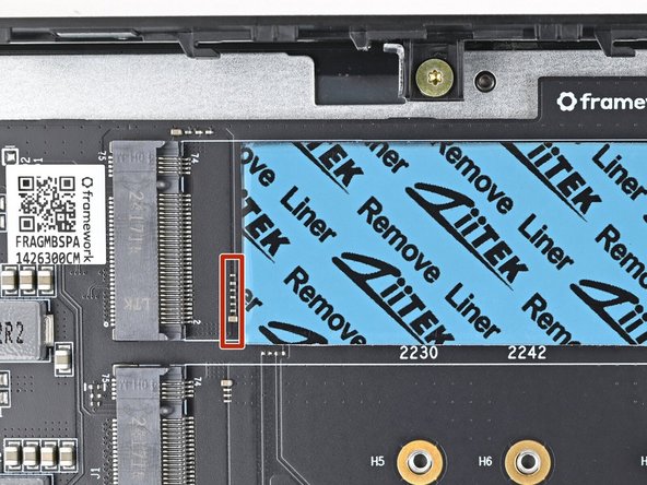
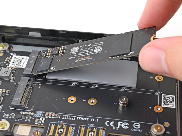
Insert the SSD into the socket at a shallow angle. The gold contacts should mostly be covered by the socket.
-
The SSD fits into the socket in one orientation. If it doesn't feel like it fits, try flipping the module.
-
-
-
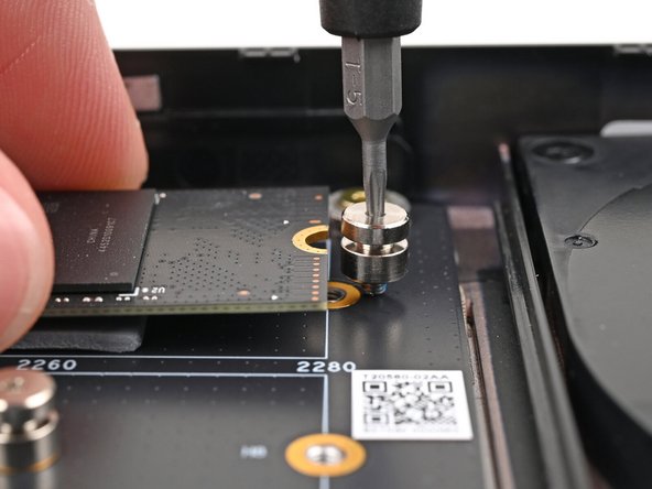
While lightly pressing the SSD into the thermal pad, guide the gap in the SSD screw into the notch on back of the SSD
-
The head of the screw should completely cover the notch and its threads should slot into the adapter's screw hole.
-
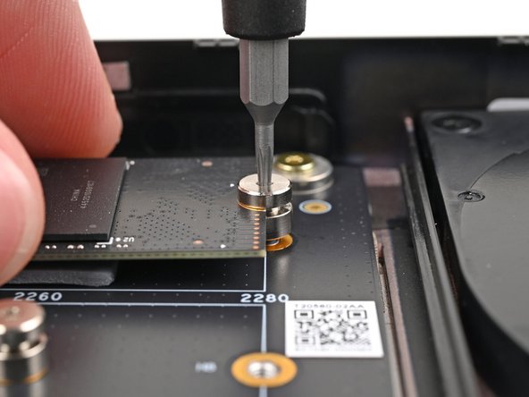
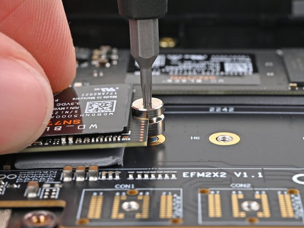
Use your Framework Screwdriver to install the 6.7 mm‑long screw securing the SSD.
-
Only tighten the screw until it feels snug. If your SSD is bending, then loosen the screw until the SSD sits flat.
-
-
-
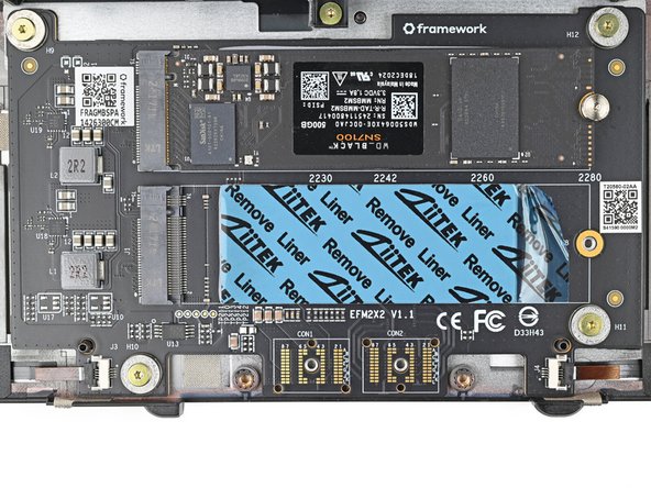
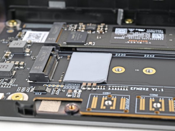
The next seven steps will show how to install an SSD that's 2260 or smaller (in this case a 2230).
-
If you're installing a single‑sided SSD (chips on only one side), grab the 2.25 mm thermal pad.
-
If you're installing a double‑sided SSD (chips on both sides), grab the 1.25 mm thermal pad.
-
Without removing any liners, place the thermal pad over the slot where you want to install your SSD.
-
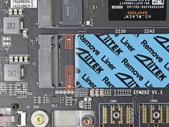
Orient the thermal pad so it sits near the small components next to the SSD's socket.
-
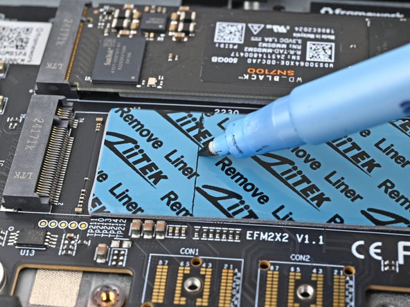
Use a marker to indicate where you need to cut the thermal pad so it fits between the socket and your SSD's screw hole—including the gold ring around it.
-
Use the SSD size numbers to judge where the screw holes and its contacts are located. The screw holes are slightly to the left of its number.
-
When you're confident in how your thermal pad should be oriented, remove it and continue to the next step.
-
-
-
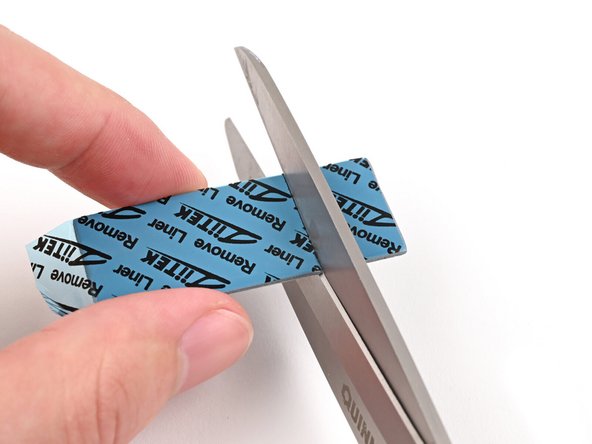
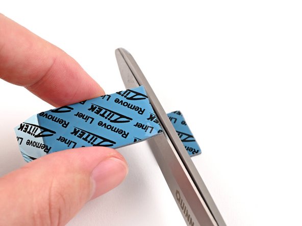
Use scissors to cut the thermal pad to your desired length.
-
-
-
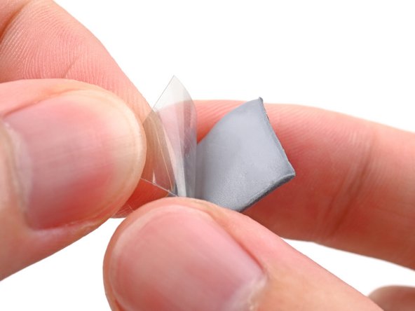
Remove the clear liner from the thermal pad to expose one side of it.
-
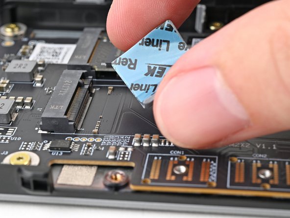
Place the thermal pad over its spot on the adapter.
-
-
-
Use your finger to gently press the thermal pad onto the adapter.
-
-
-
Remove the blue liner to expose its top side.
-
-
-
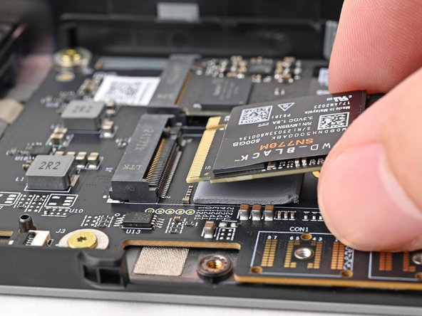
Hold the SSD by its edges. Don't touch the gold contacts with your fingers. If you do, wipe the contacts with a clean, lint-free cloth to remove any finger oils.
-
Insert the SSD into the socket at a shallow angle. The gold contacts should mostly be covered by the socket.
-
The SSD fits into the socket in one orientation. If it doesn't feel like it fits, try flipping the module.
-
-
-
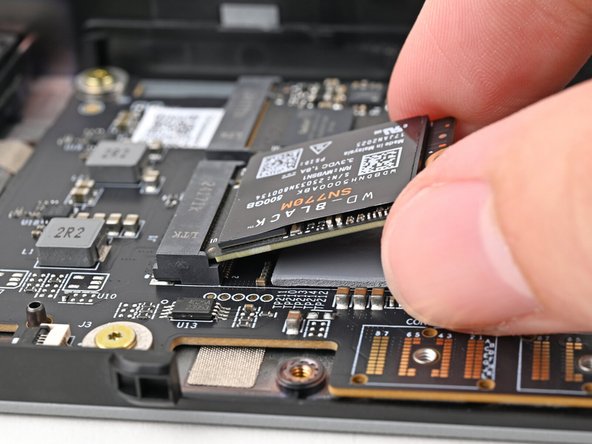
While lightly pressing the SSD into the thermal pad, guide the gap in the SSD screw into the notch on back of the SSD
-
The head of the screw should completely cover the notch and its threads should slot into the adapter's screw hole.
-
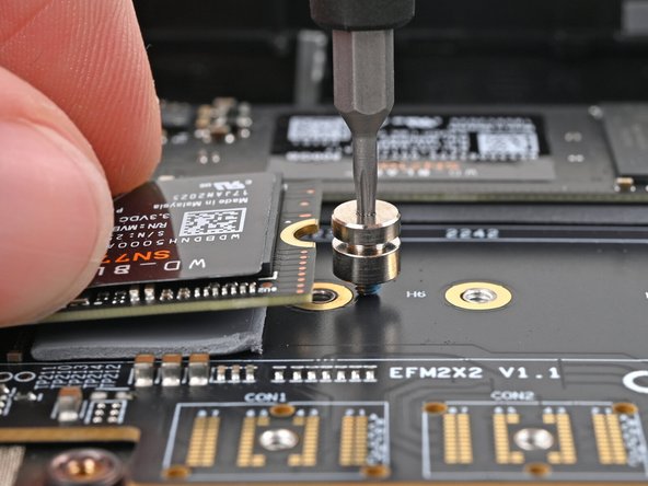
Use your Framework Screwdriver to install the 6.7 mm‑long screw securing the SSD.
-
Only tighten the screw until it feels snug. If your SSD is bending, then loosen the screw until the SSD sits flat.
-
-
-
Align the Expansion Bay Module with its slot in the laptop.
-
Check that the module sits evenly with the rail on the outside edges of the slot.
-
Check that the two center rails are threaded between the fans.
-
This example shows inserting the Graphics Module (dGPU).
-
-
-
While keeping the module level with the laptop, slide it into its slot.
-
The module should slide in easily. If you feel any resistance, pull the module out and realign it.
-
You should hear an audible "click" when the module's clips snap into place.
-
-
-
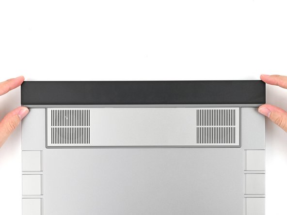
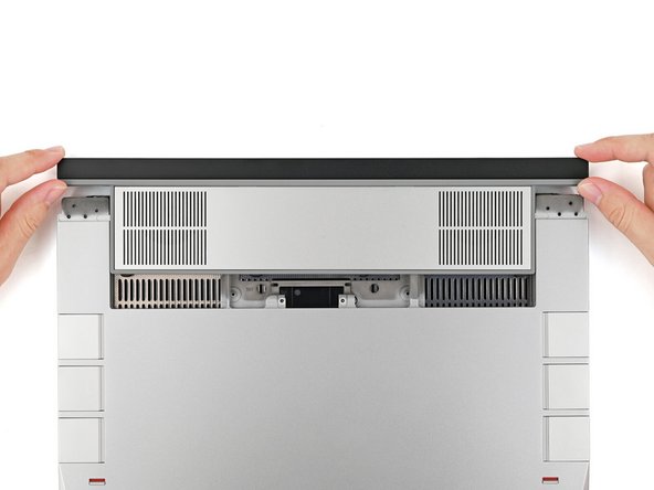
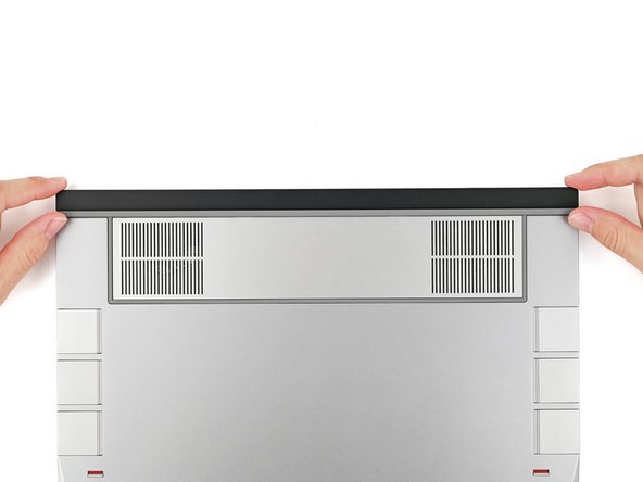
While keeping the shell level with the laptop, slide it into its slot.
-
The shell should slide in easily. If you feel any resistance, pull the module out and realign it.
-
You should hear an audible "click" when the shell's clips snap into place.
-
This example shows inserting the Expansion Bay Shell.
-
-
-
Flip over the laptop and open it.
-
Lift the interposer door by its black pull tab and let it rest upright.
-
-
-
Use your Framework Screwdriver to tighten the two captive T5 Torx screws securing the Expansion Bay Module.
-
-
-
Place the interposer over its spot between the Mainboard and the Expansion Bay.
-
Depending on if you're installing a Graphics Module or the Expansion Bay Shell, the interposer should be oriented so either rubber grommets or metal tabs cover the Expansion Bay screws.
-
-
-
If you have the Graphics Module installed, your interposer will have four screws. If you have the Expansion Bay Shell installed, you'll have three screws instead.
-
If you have the Graphics Module, use your Framework Screwdriver to tighten the four captive T5 Torx screws securing the interposer.
-
If you have the Expansion Bay Shell, use your Framework Screwdriver to tighten the three captive T5 Torx screws securing the interposer.
-
Close the interposer door.
-
-
-
Your Input Module(s) might be different, but the procedure to remove them is the same.
-
Align the top edge of the Input Module with the top edge of the laptop.
-
Lay the Input Module on the laptop and let the magnets pull the keyboard into place
-
Make sure the Input Module is seated properly on its alignment pegs and sits flush with the edges of the laptop.
-
Repeat for any remaining Input Modules.
-
-
-
Align the top edge of the keyboard with the top edge of the laptop.
-
Lay the keyboard on the laptop and let the magnets pull the keyboard into place
-
Make sure the keyboard is seated properly on its alignment pegs and sits flush with the edges of the laptop.
-
-
-
Place the Touchpad Module flat on its cutout so its clips are properly aligned.
-
Press the Touchpad Module down and slide it into place so it lines up evenly with the bottom edge of the laptop.
-
-
-
Place the Touchpad Spacer over its spot on the laptop with the bottom edge overhanging slightly.
-
Slide the Touchpad Spacer towards the top of the laptop to secure it.
-
Repeat the same procedure for the other Touchpad Spacer.
-
-
-
Push the Input Module latches back into place to lock them.
-


You finished fixing your Framework Laptop!
Take your e-waste to an R2 or e-Stewards certified recycler.
If you need help, contact Framework support.
You finished fixing your Framework Laptop!
Take your e-waste to an R2 or e-Stewards certified recycler.
If you need help, contact Framework support.
Cancel: I did not complete this guide.
6 other people completed this guide.
3 Comments
Hey there, I bought the framework 16 with expansion bay module (no GPU) when it was in pre-order stage, and now I bought the M.2 expansion module, and it turns out the interposer that came with my laptop is completely incompatible with it, the gap between the screws is different, and this isn't mentioned anywhere, the instructions even specifically explain how to use the expansion bay interposer, so what's the problem here, do I now need to also buy a newer model of the interposer?
Kamal Tufekcic - Open Reply
Amazing laptop, I was lost I had no idea this company even existed. Praises to this Company. I’m lucky I came across it while looking for hardware for a different laptop. I have one question though can you upgrade the RAM on this laptop????
Antonio Villar - Open Reply
Hi there!
All of our Laptops have upgradeable RAM/ Memory. For the Framework Laptop 16, you can see our guides on how to upgrade/ replace your RAM below;
- Framework Laptop 12 - RAM/ Memory Upgrade or Replacement
- Framework Laptop 13 - RAM/ Memory Upgrade or Replacement
- Framework Laptop 16 - RAM/ Memory Upgrade or Replacement
Our Framework Laptop 13 Pro will also have upgradeable RAM/ Memory, but our guide is not yet available for that; but will be closer to when we start shipping pre-orders out.
Iroh -