Introduction
Follow this guide to install a secondary 80mm fan in your Framework Desktop.
The Framework Desktop supports a 80mm fan with a standard 4-pin connector. For detailed fan requirements, click here.
The guide shows installing a Noctua NF-A8 80mm fan. If installing a different fan, mileage may vary.
This fan is completely optional. In thermal simulations, Framework saw that there wasn't a significant difference having the 80mm fan vs not.
Parts
No parts specified.
-
-
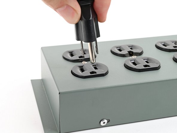
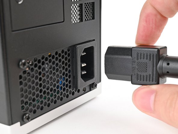
Before you begin repairs, shut down your Desktop from the operating system and unplug it.
-
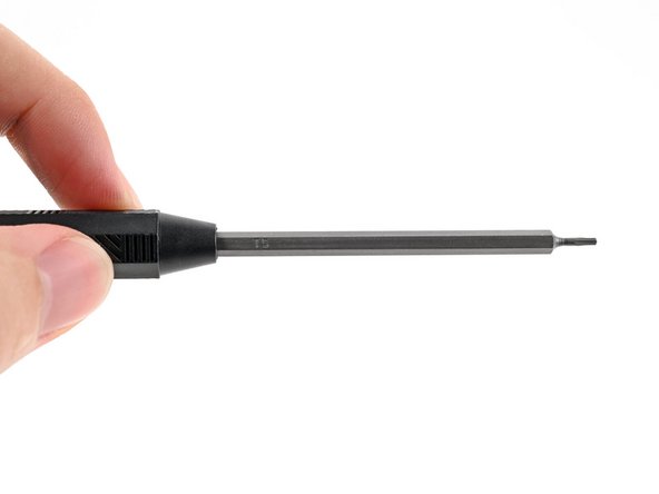
Make sure your Framework Desktop Screwdriver has the T5 Torx bit (labeled as T5) facing outwards. If it's not, pull the bit out and flip it.
-
-
-
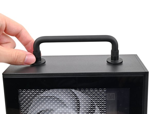
If you installed the Handle on your Desktop, follow this step. Otherwise, skip it.
-
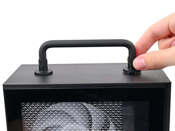
Rotate the Handle's screw threads counterclockwise on both sides until it comes free.
-
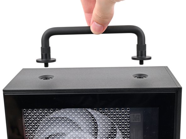
Remove the Handle.
-
-
-
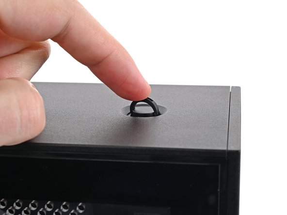
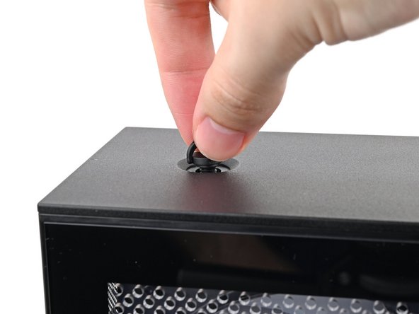
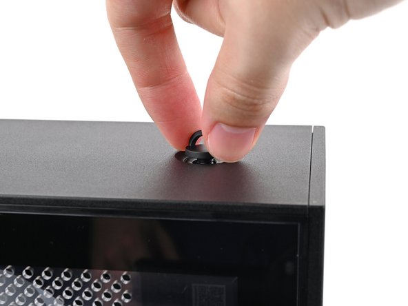
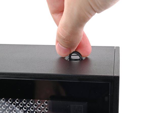
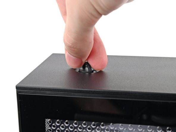
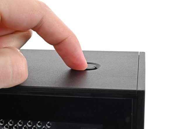
Use your finger to lift up the two D-rings on the Top Panel screws.
-
-
-
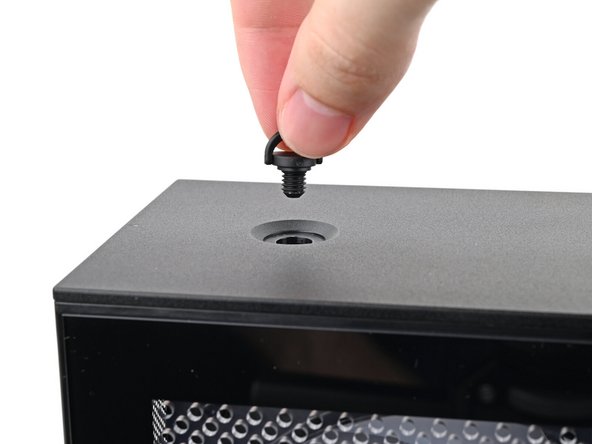
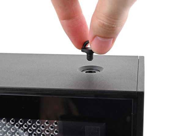
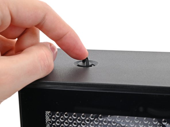
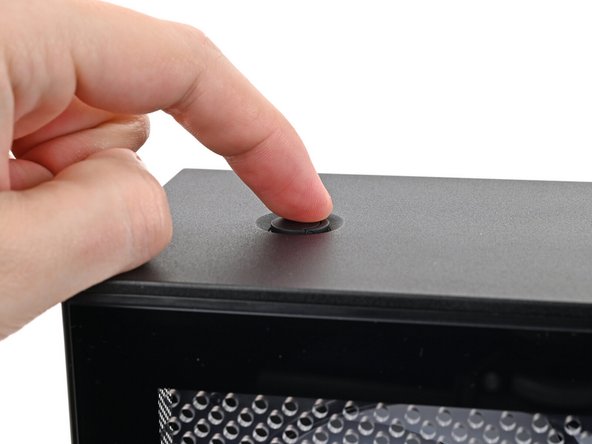
Use your fingers to twist the screw counter-clockwise and loosen it.
-
Remove the Top Panel screw.
-
-
-
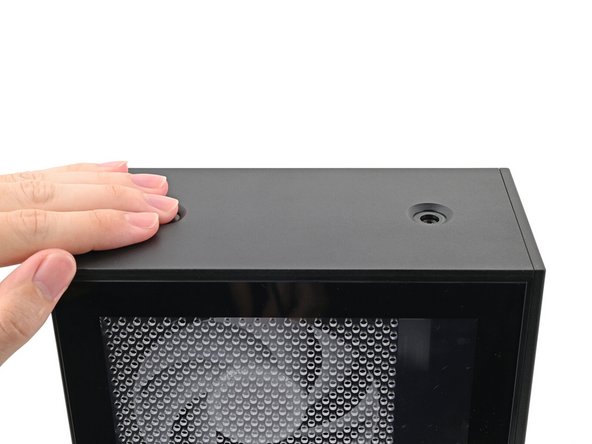
Repeat the same procedure for the other Top Panel screw.
-
-
-
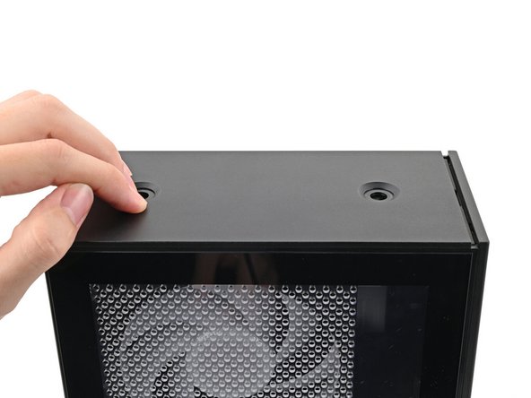
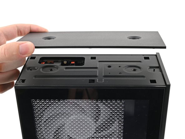
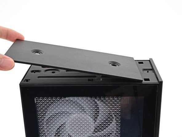
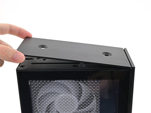
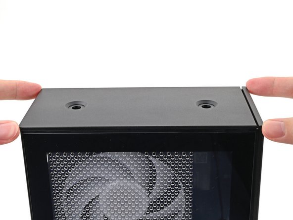
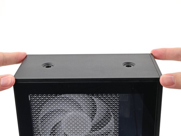
Slide the Top Panel towards the rear of the computer to release the clips securing it to the chassis.
-
If you're having a hard time gripping the Top Panel, use the screw holes to get a better handhold.
-
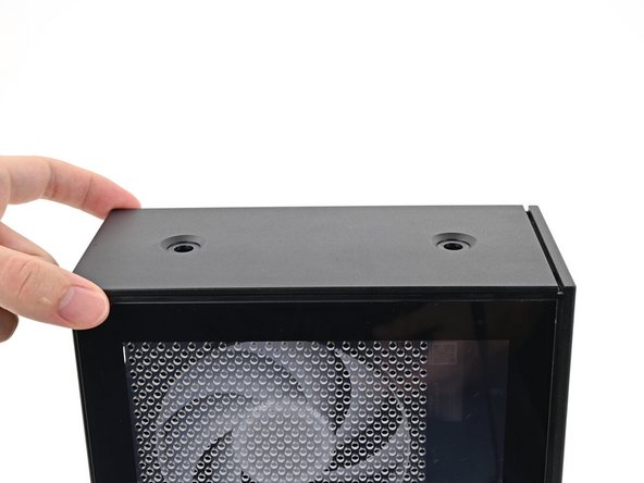
Lift the Top Panel off the chassis and remove it.
-
-
-
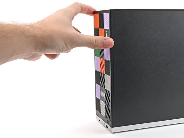
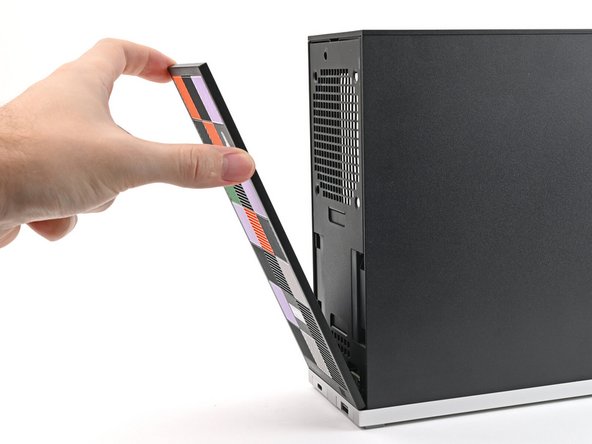
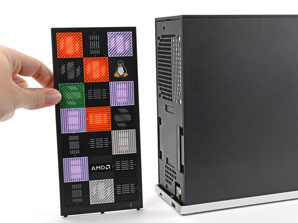
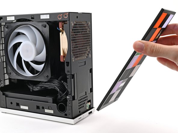
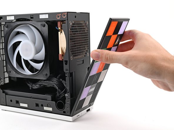
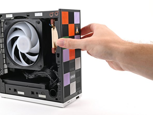
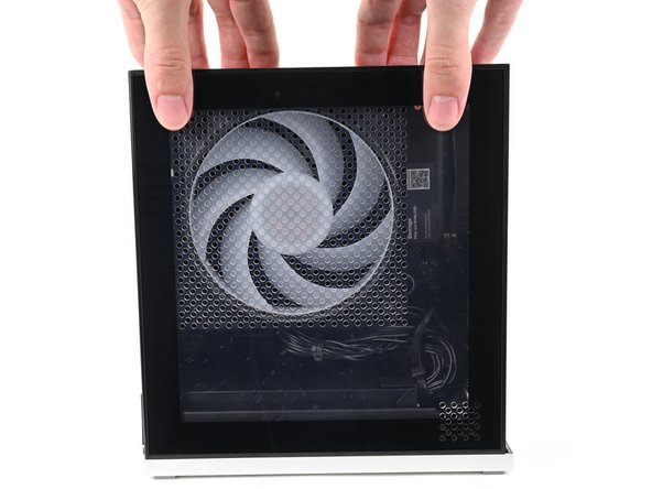
Use your fingers to pull the Front Panel off the magnets securing it to the chassis.
-
-
-
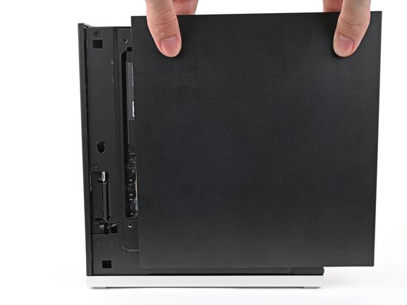
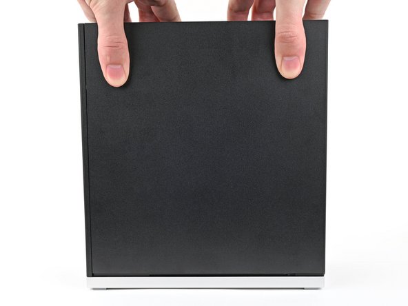
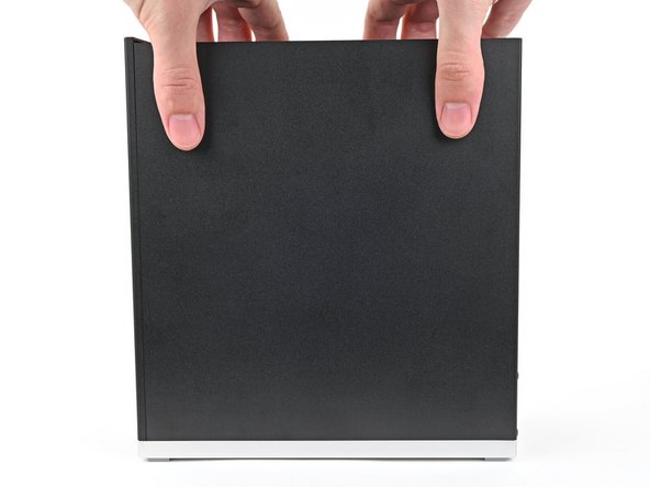
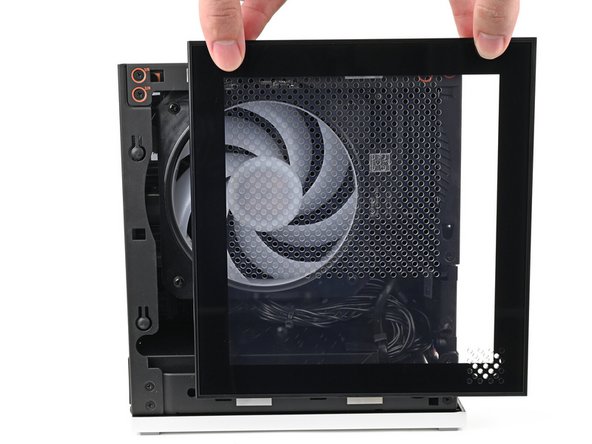
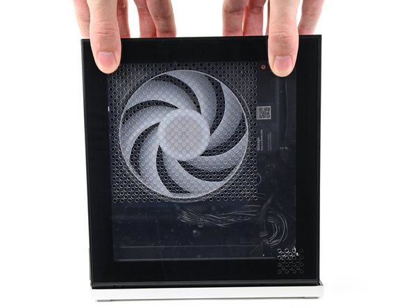
Use your fingers to grip the top of the Right Panel and slide it upward to release its clips.
-
Remove the Right Panel.
-
-
-
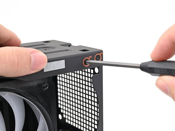
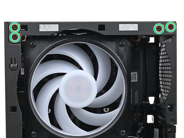
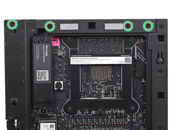
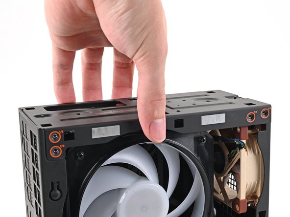
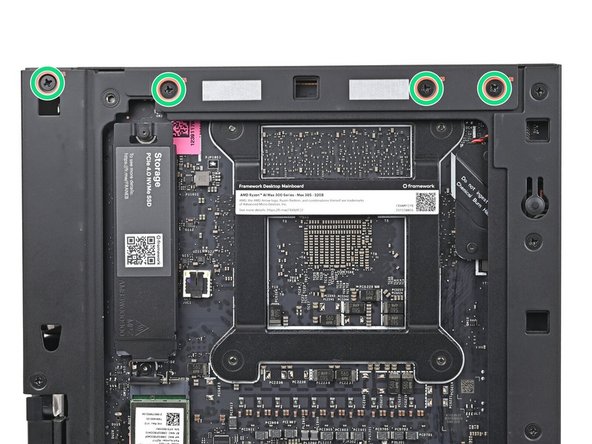
While holding the Desktop steady, use your Framework Desktop Screwdriver to remove the eight 4.0 mm‑long Phillips screws securing the top plate.
-
-
-
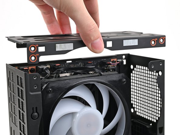
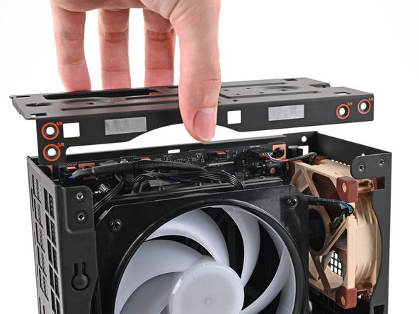
Lift the top plate off the Desktop and remove it.
-
-
-
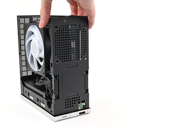
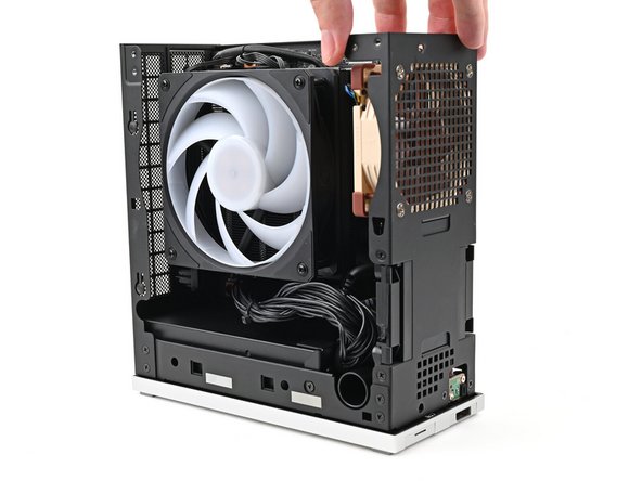
Lay the right side of the Desktop on your work surface so the Mainboard is facing upward.
-
-
-
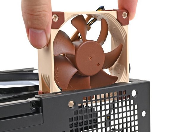
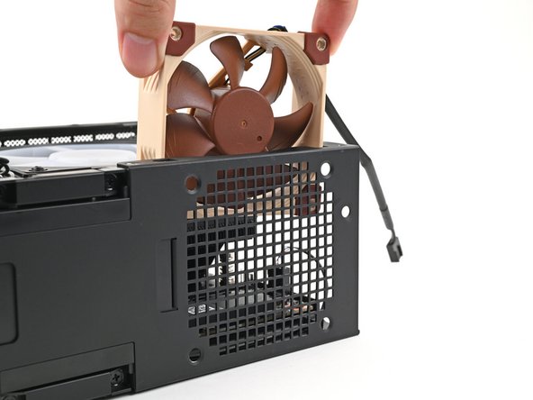
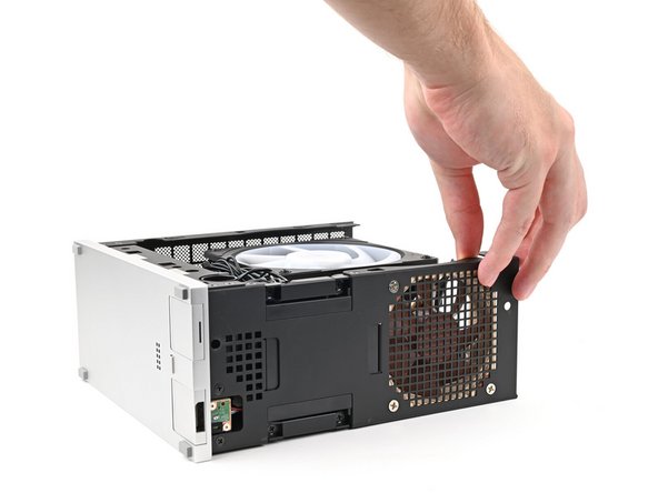
Orient the fan so its label is facing away from the chassis fan grille and the cable is pointing up.
-
If your fan has an arrow indicating airflow direction, make sure it's pointed towards the heatsink.
-
If you're using a different fan, orient it such that the fan is blowing into the Desktop, not away.
-
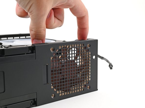
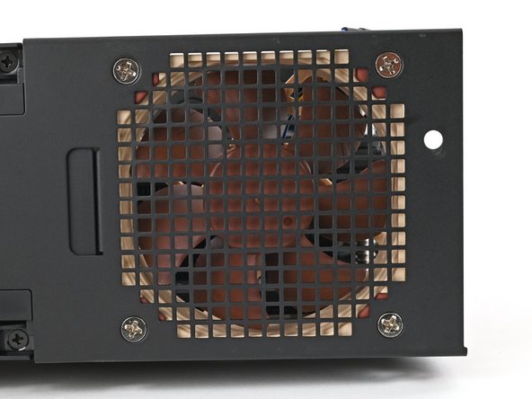
Insert the fan into the chassis and along the front plate, making sure that the screw holes in the chassis and the fan are aligned.
-
-
-
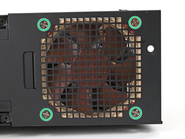
Use your Framework Desktop Screwdriver to install the four screws securing the secondary fan.
-
Most fans of this type use self-tapping screws that will carve threads into your fan's screw holes. This is normal and necessary for the fan to be secured.
-
-
-
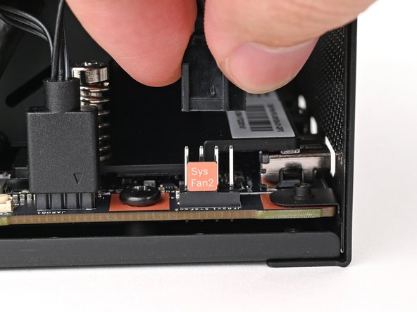
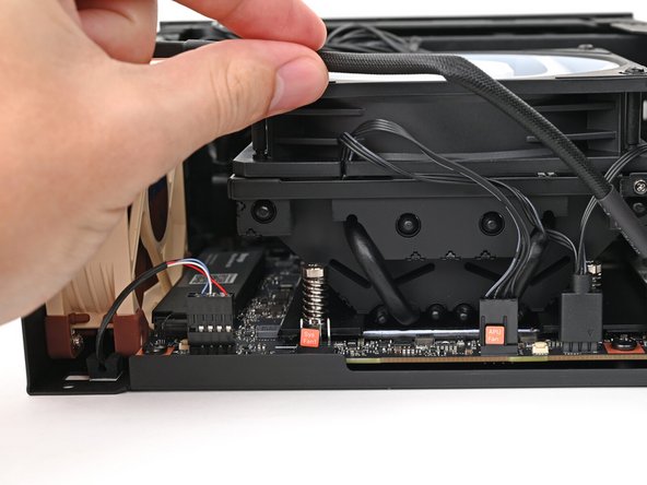
Orient the fan cable so its two vertical lines are facing you.
-
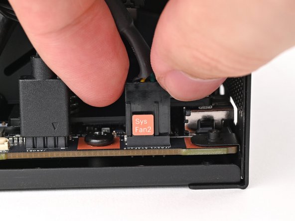
Slide the fan cable over the four-pronged connector labeled "Sys Fan 2," making sure the orange label slots between the vertical lines.
-
You can also connect the cable into the "Sys Fan 1" slot depending on the cable's length and orientation.
-
-
-
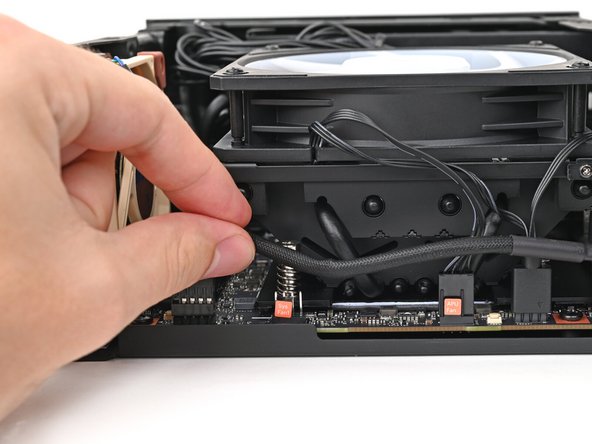
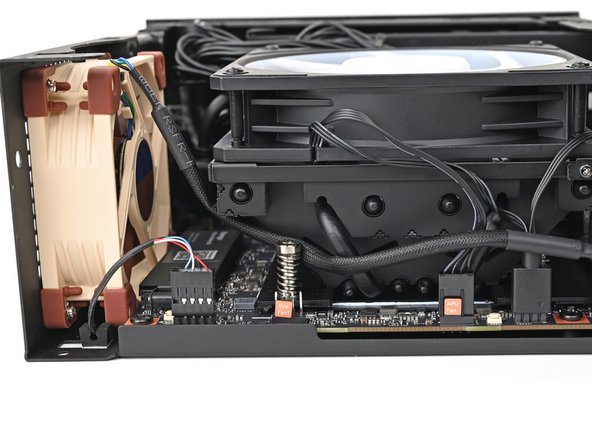
Move the fan cable underneath the heat sink and tuck it behind the silver screw post.
-
-
-
Rotate the Desktop so it sits upright on your work surface.
-
-
-
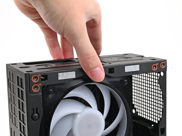
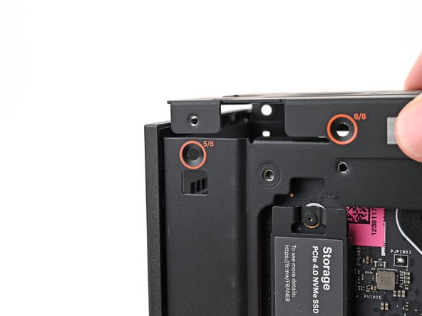
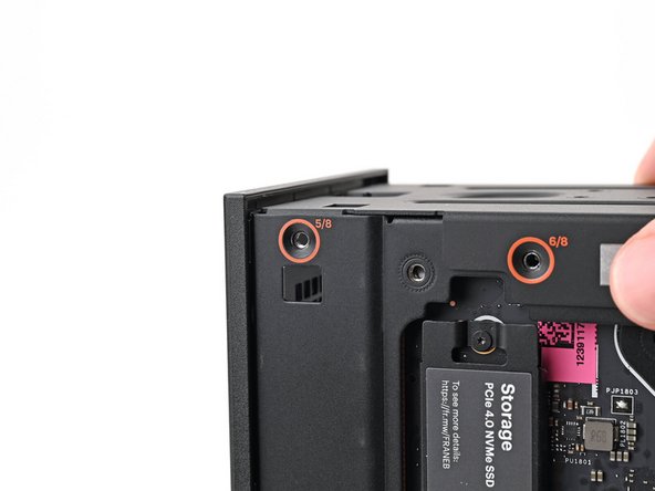
Place the top plate on top of the Desktop, making sure it slots into the chassis so the orange circles are visible.
-
-
-
Make sure the matching screw hole on the top plate labeled "5/8" is slotted on the inside of the Chassis so that the orange circle is visible.
-
-
-
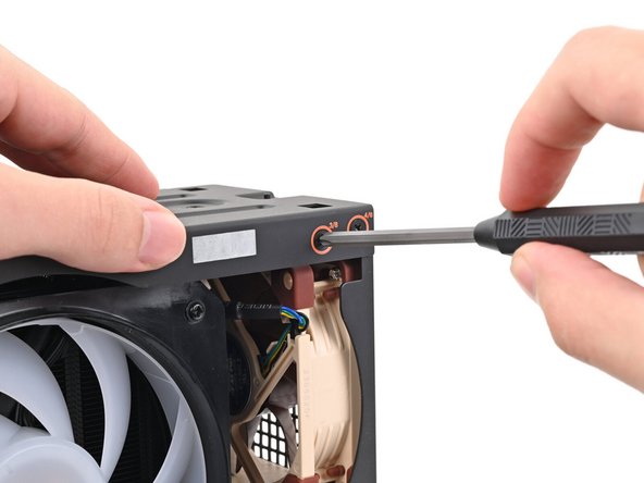
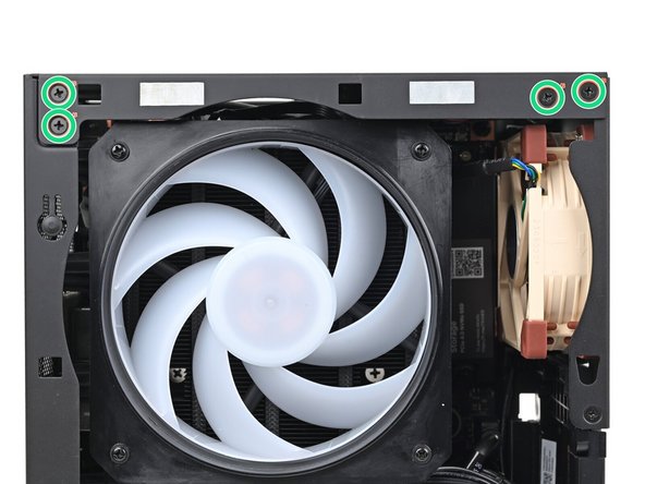
While holding the Desktop steady, use your Framework Desktop Screwdriver to install the eight 4.0 mm‑long Phillips screws securing the top plate.
-
-
-
Slide the Right Panel onto the right edge of the chassis, from top to bottom, and press it flat to ensure its clips are slotted into place.
-
There should be a small gap between the bottom of the Right Panel and the silver base.
-
Push the Right Panel towards the base of the computer to engage the clips.
-
-
-
Lay the bottom of the Front Panel on the small, protruding lip in the silver base to align its tabs.
-
Press the Front Panel flat to the chassis and let it align to the magnets.
-
-
-
Slide the Left Panel onto the left edge of the chassis and press it flat to ensure its clips are slotted into place.
-
There should be a small gap between the bottom of the Left Panel and the silver base.
-
Push the Left Panel towards the base of the computer to close the gap and engage the clips.
-
-
-
Orient the Top Panel so its arrow is pointing towards the rear of the computer.
-
While holding the Top Panel at a slight downward angle, slide it across the top of the chassis (from rear to front) until you feel its clips catch.
-
There should be a small gap between the Top Panel and the front of the Desktop.
-
Lay the Top Panel flat on the chassis to align the remaining clips.
-
-
-
While securing the computer with one hand, use the other hand to slide the Top Panel towards the front of the computer to close the gap and engage the clips.
-
-
-
Insert the top panel screw into its hole and twist clockwise until it feels snug.
-
-
-
Repeat the same procedure for the other top panel screw.
-
-
-
Use your finger to close the two D-rings on the top panel screws.
-


If you need help, contact Framework support.
If you need help, contact Framework support.
2 Comments
The link to the fan Requirements is wrong (Unauthorized). It should be pointing to Parts Compatibility for building a PC with a Framework Desktop Mainboard (AMD Ryzen™ AI Max 300 Series)
But overall, really nice explanation
Hi Paulie!
Sorry to hear you ran into this issue with the URL. Can you share where/ what step the "Unauthorized" URL is? If clicking the URL in the Introduction, it does go to the Knowledgebase page you share when double checking it myself.
Iroh -