
Introduction
How exciting, you got your hands on a Framework Laptop 13 DIY Edition! This guide will walk you through each step from unboxing to powering on your laptop so you can start using it right away. As with all of our guides, make sure you read the directions in each step and view each image first.
Please note this guide is for the Framework Laptop 13 (AMD Ryzen™ 7040 Series) only, if you are setting up one our Intel Core Laptops please refer to the appropriate guide here.
After finishing the Quick Start Guide, if you’re installing Windows, check out our Windows 11 Installation Guide and don’t forget to install the Framework Laptop Driver Bundle. You can also check out our Linux compatibility page for the distros that work great on the Framework Laptop.
If you have questions or run into any issues, check out the Support pages.
Tools
Parts
No parts specified.
-
-
The first step is to open the box and identify the contents, the exact contents will vary depending on how you configured your Laptop, but inside the box you will find:
-
Bezel
-
Input Cover
-
Framework Laptop 13
-
Power Adapter
-
Expansion Cards
-
Storage, Memory, any additional Expansion Cards and importantly the Framework Screwdriver!
-
Note that depending on the retail packaging for Memory , this may be located underneath the Power Adapter instead.
-
-
-
Start by unpacking the box containing your Framework Screwdriver, Memory and Storage, these are all together in the box found underneath the Laptop.
-
You may also want to remove the Expansion Cards from their boxes at this stage too!
-
-
-
Open the Laptop as pictured and you will find a clear protective cover as pictured, this can simply be lifted off and set aside.
-
This protective cover is made of post-consumer recycled PET and is highly recyclable. We recommend this can be disposed of with other household plastic recycling.
-
-
-
Please make sure you are using DDR5 Memory as DDR4 Memory is not compatible with this Mainboard.
-
There are black mylar sheets covering the memory slots. These can be gently bent up to insert your memory modules.
-
Note: If you are using one Memory module, place it in the right socket that is labelled “Channel 0."
-
Insert the Memory module into the Mainboard by aligning the notch on the Memory module with the notch on the socket. Note that for Channel 1 the notch is reversed so the Memory stick may need to be inserted "upside down" with the chips facing down depending on the brand used.
-
Make sure that the memory is fully inserted before proceeding.
-
Once the module is fully inserted, it will rise up at a 20-degree angle. Gently press it down towards the Mainboard until the clips located at the top and bottom of the receptacle snap into place.
-
The first boot after installing a new Memory module will take longer than normal, as the system prepares itself for the new module.
-
-
-
Using the T5 bit in the Framework Screwdriver, unscrew the fastener that is used to secure the Storage module.
-
Align the notch on the Storage module with the notch on the socket and slide the module into the Mainboard.
-
Once properly inserted the module will rise up at a 20-degree angle.
-
Using one finger gently hold the Storage module down to the Mainboard and use your other hand to screw in the fastener using the T5 bit in the Framework Screwdriver.
-
Be sure to not over-tighten the fastener.
-
-
-
Gently place the Input Cover keyboard side down on the Bottom Cover as indicated on the image. The cover should be about an inch and a half away from the bottom of the Mainboard so that you can comfortably install the Touchpad Cable.
-
Note: The orientation of the Input Cover matters. Study the first image in this step to ensure you are properly attaching the cover.
-
Locate the loop on the end of the Touchpad Cable and insert your finger into it.
-
-
-
Using slight force, connect the Touchpad Cable by aligning it to the socket on Mainboard. You should hear it click into place once properly connected.
-
-
-
Before closing up the laptop, make sure that the Touchpad end of the Touchpad Cable is fully seated in the receptacle.
-
The cable should be inserted far enough that the white line almost touches the receptacle.
-
If it is not inserted far enough, you'll need to flip up the black latch on the other side of the connector, slide the cable in further, and then close the black latch again.
-
-
-
Once the Touchpad cable is secured to the Mainboard, flip the Input Cover over the Bottom Cover so that the keyboard is facing up and attach it to the Bottom Cover by aligning the top and bottom edges of both covers.
-
Tip: The covers are magnetic and should fit into one another easily. If you feel any resistance simply lift the Input Cover up and try again.
-
Note that the Input Cover will not sit entirely flat until the bottom fasteners are tightened. The bottom right corner is slightly lifted to make it easy to remove the Input Cover.
-
-
-
If installing a new Bezel, remove the liner pieces on the bottom of the Bezel to expose the adhesive (if present).
-
-
-
Open the Framework Laptop 180 degrees to attach the Bezel.
-
Starting with the bottom of the Bezel which covers the hinges and cables, align the corners of the Bezel to the display and place it down. The Bezel is attached by magnets and should easily click into place.
-
We recommend feeling along each edge of the Bezel to make sure it is seated correctly before proceeding, if it doesn't seem to be sitting flush, lift it back up and try lowering it into place again.
-
Do not try to install the Bezel without first opening the Laptop fully, doing so could damage the Bezel and potentially the Display.
-
If the bottom of the Bezel doesn't seem to fit, lift it back off and check that the cables are seated correctly on both sides. If the Bezel doesn't seem to fit at all, please contact support and do not force it into place.
-
-
-
Close the Framework Laptop and place it upside down to reveal the fasteners on the Bottom Cover.
-
Using the T5 bit in the Framework Screwdriver, screw all 5 fasteners back into the Bottom Cover.
-
Be sure to not over-tighten the fasteners.
-
-
-
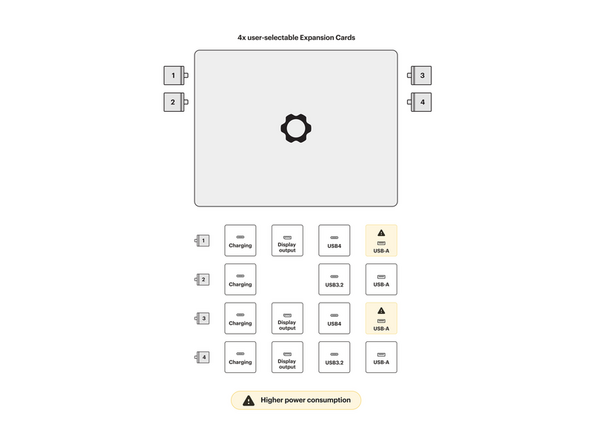
Insert the Expansion Cards of your choice. With keyboard face up, this configuration supports USB4/DP for the upper left and right slots, USB 3.2 only for the lower left slot and USB 3.2/DP for the lower right slot. All ports can be used for charging via USB. A diagram of Expansion Card compatibility can be found here.
-
Note that USB-A Expansion Cards when placed in the back two slots will result in higher power consumption. Check the KB article for more detail on this.
-
The text, logo, and QR code on the Expansion Card must be facing down (facing the laptop). Slide the Expansion card into the bay. Using two or more fingers push the card until into the bay until it clicks.
-
You will have to use a slight amount of force to ensure proper installation of the Expansion Cards.
-
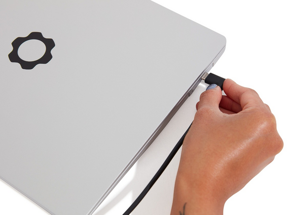
Plug your power cable into the USB-C Expansion Card.
-
Open the lid on your Framework Laptop and press the power button.
-
Note that your first boot will take a while before the logo comes up on screen as the system does memory training. The more memory you've installed, the longer this could take (on the order of a minute or two with 64GB!)
-
-
-
As the Windows 11 Installer does not include the necessary drivers for the AMD RZ616 Wi-Fi card, you will need to create install media which removes the requirement for an online Microsoft Account during set up by following this guide.
-
Installing Linux: Check the links below for recommended Linux distros and installation instructions:
-
-
-
-
-
After installing your Operating System you will also need to install the latest Framework Laptop Driver Bundle.
-
We recommend checking that you are running the latest Framework Laptop BIOS too.
-


Cancel: I did not complete this guide.
74 other people completed this guide.
4 Comments
Power button lit up, and screen backlight, but nothing else for 10 minutes. I shifted the 32gb memory stick to the other slot and re-seated the storage... Again, lights on but no one is home. What can I try next?
Fantastic! I've built 3D printers before with DIY kits such as the Prusa i3 Mk3 and compared to that, this was very easy and fast.
Fifthdread - Resolved on Release Reply