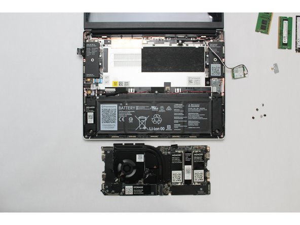
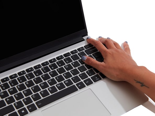
Introduction
Before you get started, if you are running Windows, there are a few steps you'll need to take:
- If you’re upgrading from an 11th Gen Intel Core system running Windows 10 to an AMD Ryzen 7040 series system, we recommend upgrading to Windows 11 before swapping the Mainboard.
- Make sure you back up your data.
- If you’re running a Pro version of Windows, suspend BitLocker by following our directions here.
- If you're running a Home version of Windows and have enabled Windows Device Encryption, you will want to disable it. To disable it, press Win + I to open Settings and select Privacy & Security. Then, click on Device Encryption on the right panel and toggle the setting to Off.
- Find your product key or link your Windows license to a Microsoft account to make sure you can re-activate Windows after the change.
This guide combines many of the possible upgrades introduced with AMD Ryzen 7040 Series so if you are skipping one or more of the upgrades please see which steps to skip below (if you are simply carrying out one of these upgrades we recommend the dedicated guide for that component).
- The guide assumes you are upgrading your Mainboard but if you are not, you can skip steps 8-9, and steps 13-18.
- If you are not upgrading your Battery you can skip step 7 and steps 19-24.
- If you are not upgrading your Hinges you can skip steps 27-30
- If you are not upgrading your Display but are upgrading Hinges, there are no steps to skip (as you will need to remove the Display in order to upgrade Hinges)
- If you are not upgrading both Display and Hinges you can skip steps 25-34
Tools
-
-
If you are on Windows, before swapping your Mainboard to the AMD version, you'll need to pre-install the RZ616 WiFi drivers by downloading and running the latest Framework Driver Bundle for AMD Ryzen™ 7040 Series. Note that you'll need to run the same Driver Bundle installer again after swapping in the AMD powered Mainboard and RZ616 card.
-
You should run the Driver Bundle linked above for AMD Ryzen™ 7040 Series even if the Mainboard you are replacing is an Intel® Core™ Mainboard.
-
-
-
Power off the Framework Laptop by navigating to the Windows icon on the bottom left and clicking on "Power" followed by "Shut down," or if on Linux, the equivalent action there.
-
-
-
Unplug your power cable from the USB-C Expansion Card in your Framework Laptop.
-
-
-
Close your laptop completely and turn it over so you can access the Expansion Cards.
-
While keeping the release button pressed, use your other fingers to slide the Expansion Card away from the laptop.
-
Important: You may have to use a little bit of force to fully disconnect the Expansion Card.
-
Make sure each Expansion Card is fully removed before proceeding to the next step.
-
-
-
Close the lid on your Framework Laptop and place it upside down on a soft, non-marring surface, such as the bag that it shipped in.
-
Using the T5 bit in the Framework Screwdriver, unscrew the 5 fasteners on the Bottom Cover. These fasteners will remain attached in the Bottom Cover so that you do not lose them.
-
The fastener on the bottom left (circled in red) will not unscrew as far as the others, as it is acting as a lifter for the Input Cover.
-
You'll hear this fastener start clicking as you rotate when it is unscrewed far enough.
-
Do not use a powered tool for these steps, as this will likely result in damage to the fasteners.
-
-
-
Flip the Framework Laptop back over and open the lid to around 120 degrees.
-
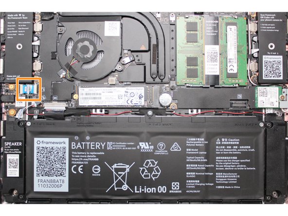
Important: Pull the Input Cover off carefully as it is still attached to the Mainboard via the Touchpad Cable. You don't need to disconnect this cable to do most repairs. You can just flip the Input Cover over. If you do want to disconnect it though, make sure to disconnect the Mainboard side using the finger loop over the orange label.
-
The bottom right corner of the Input Cover lifts up when the five fasteners are properly unscrewed from the previous step. You should not have to use any excessive force to remove the Input Cover.
-
Carefully lift the cover up from the bottom right corner. If you need to, you can use the spudger end of the Framework Screwdriver to lift it as well. Lift the Input Cover off the Mainboard, flip it over (keyboard side down), and place it about halfway on the Bottom Cover.
-
Be sure not to put too much force on the Touchpad Cable when doing this.
-
If the LEDs on the left and right sides of the system are flashing red when you lift off the cover, it means the system is still powered on. Make sure your power cable isn't plugged in and that you have shut down correctly.
-
Note that it may take up to 30 seconds after shutting down for the system to fully power off. Wait until the LEDs stop flashing before proceeding.
-
You should keep the Battery connector plugged in unless you need to replace the Battery, Mainboard, or Speakers. This connector is easy to accidentally damage, so it's better to not handle it.
-
-
-
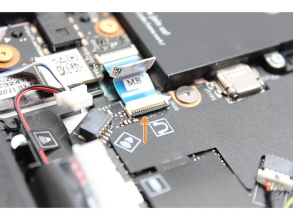
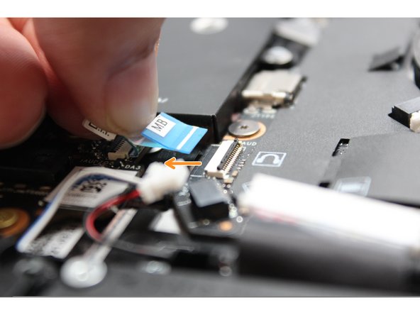
Disconnect the Touchpad Cable from the Mainboard by inserting your finger into the loop and pull directly upward using a slight amount of force.
-
Avoid disconnecting the Touchpad side of the cable unless you need to replace the Touchpad Cable itself, since that connector is more fragile.
-
Once the Touchpad Cable is disconnected, remove the Input Cover away from the Mainboard.
-
The Input Cover is now fully disconnected from the Bottom Cover and can be set aside.
-
-
-
Be extremely careful when sliding the Battery connector out, as it is very easy to accidently bend the pins. Make sure to slide straight down, and avoid letting the connector twist or bend.
-
Gently disconnect the Battery by gripping the connector edges with both fingers and slide the connector straight down from the socket.
-
-
-
Using both fingers and a slight amount of force, disconnect the Speaker cable from the Mainboard by pulling it straight out.
-
-
-
Disconnect the Audio Flex Cable from the Mainboard. Using your fingernail or the spudger end of the Framework Screwdriver flip up the black latch on the connector and then gently slide the cable out of the connector.
-
There should be no resistance when disconnecting this cable.
-
-
-
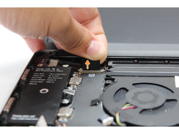
Using your fingers, carefully disconnect the Display cable on the top, left hand side by using the pull tab to pull it upward.
-
-
-
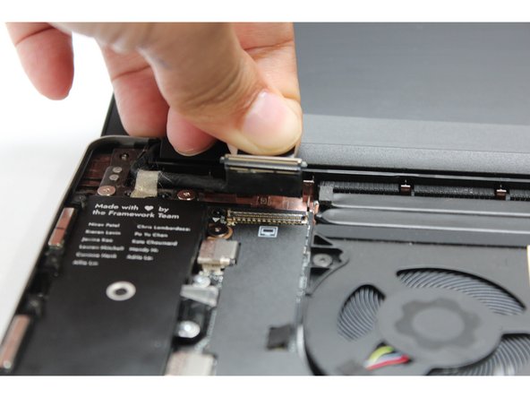
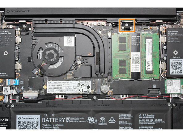
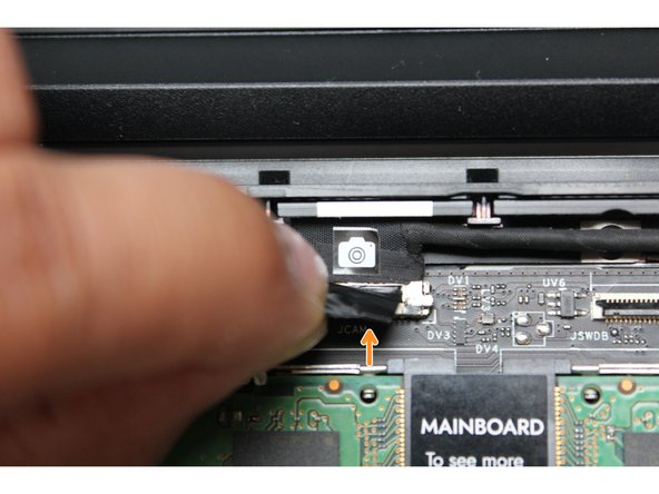
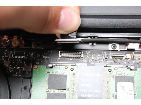
Using your fingers, carefully disconnect the Webcam cable on the top, right hand side by using the black pull tab to pull it directly upward.
-
-
-
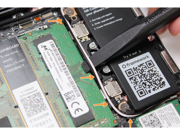
Using the spudger end of the Framework Screwdriver, release the black and white WiFi Antenna cables by gently lifting them out from the rubber holders.
-
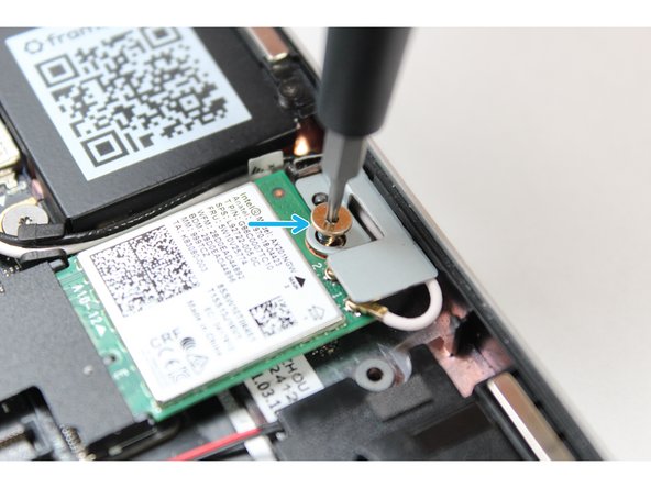
Unscrew the fastener in the silver bracket holding down the WiFi module.
-
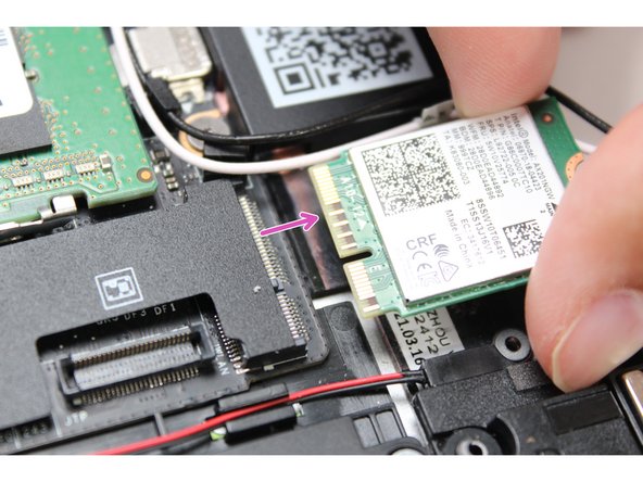
Remove the WiFi bracket and gently pull the WiFi module out of the socket as indicated in the image.
-
You do not need to disconnect the black and white WiFi Antenna cables from the WiFi module. Keeping them connected will make it easier to insert the card back into place.
-
-
-
If you are planning on reusing your currently Mainboard, you can skip this step and leave the DDR4 Memory installed as the new Mainboard uses DDR5 Memory.
-
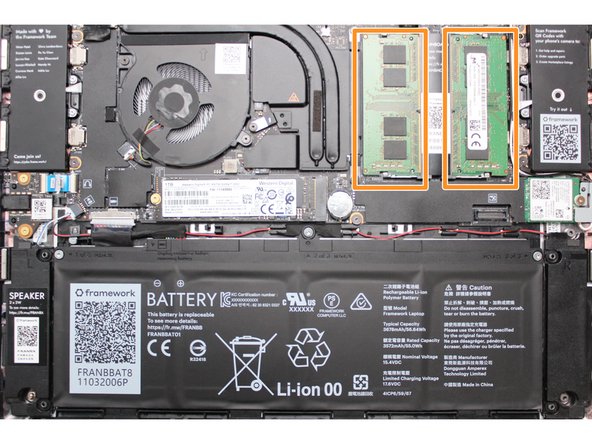
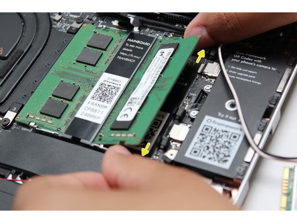
Using both fingers, gently pull the top and bottom metal release clips away from the Memory just enough for the module to pop up.
-
The top and bottom clips should be released simultaneously for a single Memory module.
-
The Memory module will pop up at a 20 degree angle. Carefully slide it out of the socket and remove it from the Mainboard.
-
If you have more than one Memory module in place, repeat the steps for the other module.
-
-
-
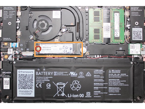
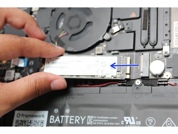
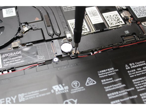
Unscrew the fastener holding down the Storage.
-
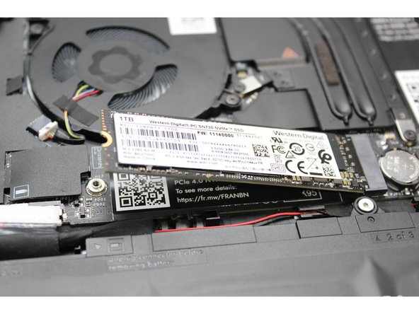
The Storage module will pop up at a 20 degree angle.
-
Slide the module out of the socket using a straight motion and remove it from the Mainboard.
-
-
-
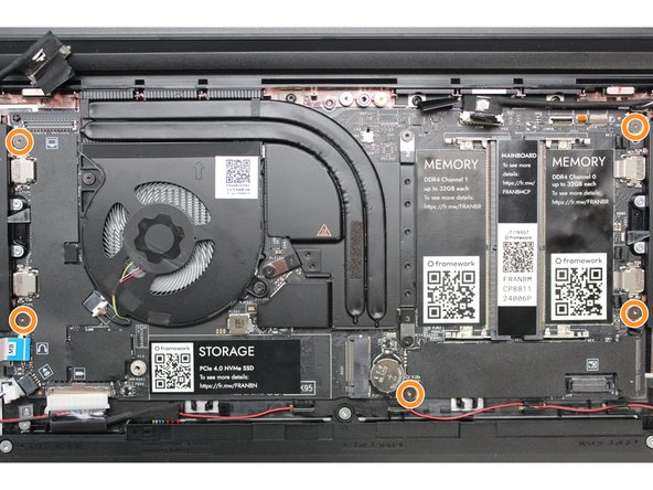
Using the T5 bit in the Framework Screwdriver, unscrew the five fasteners holding down the Mainboard.
-
These fasteners will completely come out. Be sure to keep them in a safe place during the replacement so that you do not lose them!
-
-
-
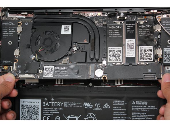
In order to lift the Mainboard off the Bottom Cover, grab it from the bottom edges and lift up very gently. There should be no resistance when lifting up the Mainboard unless a previous step was missed.
-
The components located underneath the Mainboard are highly sensitive. Be sure to handle the board by the edges, and avoid touching any components on the board.
-
The Mainboard is now fully disconnected from the Framework Laptop.
-
-
-
The easiest way to properly install the Mainboard is by aligning the two alignment pins on the Bottom Cover with the two holes on the Mainboard.
-
Take a close look at the actual Mainboard and you'll notice two small holes. You will see one hole on the top right and the other on the top left-hand side of the Mainboard as indicated in the first image with the orange arrows.
-
The alignment pins are located on the Bottom Cover as indicated with the green arrows in the second image.
-
Place the Mainboard on the Bottom Cover by using the alignment pins as a guide. Place the holes in the Mainboard directly over pins in the Bottom Cover. Both the left and right-hand side pins should fit into the holes perfectly.
-
The components located underneath the Mainboard are highly sensitive. Be sure to handle the board by the edges, and avoid touching any components on the board.
-
Once you have placed the Mainboard down be sure to make sure that the Speaker cable, Display cable, Camera cable, WiFi antenna cables, Audio Board cable, or the Battery cable are not stuck between the Mainboard and Bottom Cover as all the cables will need to be reconnected into their respective sockets after the Mainboard is secured in place.
-
-
-
Using the T5 bit in the Framework Screwdriver, screw the five fasteners into the Mainboard once it is properly seated.
-
Be sure to not over-tighten the fasteners.
-
-
-
Using the T5 bit in the Framework Screwdriver, unscrew the three fasteners on the battery.
-
Note: The screws will come loose after a few revolutions however they will remain attached to the battery.
-
-
-
Use your finger tips to gently lift the battery up and away from the bottom cover. Carefully lift it out and keep it in a safe place.
-
Warning: Handle the battery by the plastic frame, make sure not to bend, scratch, cut, or puncture it, and keep it away from heat sources
-
-
-
While handling the Battery with the plastic frame, slide it into the Bottom Cover. Use the first image as a reference.
-
-
-
Before plugging the Battery connector back in, double check the pins on the Battery receptacle on the Mainboard, and make sure none of them look bent.
-
Don't plug the Battery connector in if pins look bent, as that will bend them even further. Reach out to Framework Support for guidance.
-
If you feel resistance when plugging in the Battery connector, stop, slide the connector back out, and make sure that no pins are being bent.
-
-
-
Carefully slide the Battery connector back into the Mainboard, gripping both edges of the connector and sliding in straight without letting the connector twist or bend.
-
-
-
Using the T5 bit in the Framework Screwdriver, screw the three fasteners into place.
-
The battery is now fully connected to the Framework Laptop.
-
-
-
Open the Framework Laptop 180 degrees to remove the Bezel.
-
The Framework Bezel is attached by magnets so you will not require any tools to remove it. Just use your fingernail and pry the Bezel away from the display from one of the top corners of the Framework Laptop.
-
Once the Bezel starts peeling off towards the bottom of the Display, lift it up using caution. You might feel a little resistance due to the adhesive at the bottom of the display.
-
-
-
Using the T5 bit in the Framework Screwdriver, unscrew the 4 fasteners connecting the Display to the Top Cover.
-
The Display is now fully unattached to the Top Cover, you can gently lift it up from the corner using your fingernail.
-
Be sure to only handle the Display by the side edges and avoid touching the bottom area.
-
-
-
Rotate the lid back up to a 90 degree angle to make it easier to remove and install the Hinges.
-
With the T5 bit in your Framework Screwdriver, unscrew the four fasteners that hold the Hinges into the Bottom Cover.
-
Note that these fasteners are longer than the ones used to attach the Display and Hinges into the Top Cover. Make sure to keep them separate from those.
-
With the Top Cover assembly now unfastened from the Bottom Cover assembly, lift it up and lay it flat, being careful to not pull on the cables too much.
-
-
-
Move the Antenna and Webcam cables out of the way carefully to make sure you have easy access to the fasteners on the right Hinge.
-
Unscrew the three fasteners on the right Hinge using the T5 bit in your Framework Screwdriver, and then remove the Hinge from the Top Cover.
-
Repeat this for the three fasteners on the left Hinge and remove the Hinge from the Top Cover.
-
-
-
Pre-rotate the new Hinges to a 90 degree angle to make them easier to install.
-
Place the left and right Hinges into the Top Cover and fasten them into place with the three fasteners each that you previously removed.
-
Carefully place the Top Cover assembly with the Hinges installed onto the Bottom Cover assembly and fasten the left and right Hinges into the Bottom Cover using two fasteners each that you previously removed.
-
-
-
Stick the antenna cables down onto the new Hinge.
-
Route the antenna cables through the hinge area, with the white and black cables sitting flat against the bottom of the Bottom Cover as much as possible. Avoid letting the cables twist or overlap, as this will interfere with the Input Cover and power button. You can use the spudger end of the Framework Screwdriver to help push the cables.
-
Route the antenna cables through each of the channels and rubber brackets.
-
-
-
There are four alignment pins located on the Top Cover. They are located right next to the four fastener slots. Place the silver brackets connected to Display directly over the pins.
-
Be sure to only handle the Display by the side edges and avoid touching the bottom area.
-
-
-
Using the T5 bit in the Framework Screwdriver screw the four fasteners into place.
-
Be sure to not over tighten the fasteners.
-
-
-
Route the black Display Cable through the routing channel as indicated in the picture.
-
Secure the silver grounding tape as indicated in the first image.
-
Using the black pull tab, align the Display Cable connector with the connection on the Mainboard and firmly press down.
-
The Display installation is now complete.
-
-
-
If installing a new Bezel, remove the liner pieces on the bottom of the Bezel to expose the adhesive (if present).
-
-
-
Open the Framework Laptop 180 degrees to attach the Bezel.
-
Starting with the bottom of the Bezel which covers the hinges and cables, align the corners of the Bezel to the display and place it down. The Bezel is attached by magnets and should easily click into place.
-
We recommend feeling along each edge of the Bezel to make sure it is seated correctly before proceeding, if it doesn't seem to be sitting flush, lift it back up and try lowering it into place again.
-
Do not try to install the Bezel without first opening the Laptop fully, doing so could damage the Bezel and potentially the Display.
-
If the bottom of the Bezel doesn't seem to fit, lift it back off and check that the cables are seated correctly on both sides. If the Bezel doesn't seem to fit at all, please contact support and do not force it into place.
-
-
-
Using two fingers, slide the Speaker cable into the Mainboard using a straight motion and a slight amount of force.
-
-
-
Connect the Audio Board cable by gently sliding it into the Mainboard. Make sure the black latch on the connector is flipped up so that you can slide the Audio Board Cable into the connector. Slide the cable straight in until the white line is almost at the edge of the connector
-
Using your finger or the spudger end of the Framework Screwdriver, flip the black latch down towards the Mainboard to lock the cable in place.
-
Once the black latch is secure the Audio Board cable should not come loose.
-
-
-
Hold the pull tab on the Webcam cable and connect it into the Mainboard by aligning the pins from the cable with the socket pins on the Mainboard.
-
-
-
Make sure that both the black and white WiFi Antenna cables are connected to the module and are rotated downwards as indicated in the second picture with the blue arrows.
-
Insert the WiFi module into the Mainbord by aligning the notch on the module with the notch on the socket.
-
-
-
Once the module is properly inserted into the Mainboard, carefully route both the black and white WiFi Antenna cables into the black rubber routers as indicated in the first image. Place both the cables behind the metal structure located near the top right of the WiFi module as well.
-
Important: The WiFi Antenna cables should not touch the Speaker located below the module as indicated in image one.
-
Place the silver bracket over the WiFi module and place the fastener in the hole. Using the T5 bit in the Framework Screwdriver, screw the fastener into place.
-
If you are using the new plastic WiFi bracket (shown in the third image) the bracket is attached to the card and contains its own fastener for easier installation.
-
-
-
Please make sure you are using DDR5 Memory as DDR4 Memory is not compatible with this Mainboard.
-
There are black mylar sheets covering the memory slots. These can be gently bent up to insert your memory modules.
-
Note: If you are using one Memory module, place it in the right socket that is labelled “Channel 0."
-
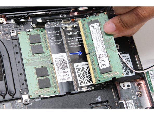
Insert the Memory module into the Mainboard by aligning the notch on the Memory module with the notch on the socket. Note that for Channel 1 the notch is reversed so the Memory stick may need to be inserted "upside down" with the chips facing down depending on the brand used.
-
Make sure that the memory is fully inserted before proceeding.
-
Once the module is fully inserted, it will rise up at a 20-degree angle. Gently press it down towards the Mainboard until the clips located at the top and bottom of the receptacle snap into place.
-
The first boot after installing a new Memory module will take longer than normal, as the system prepares itself for the new module.
-
-
-
Using the T5 bit in the Framework Screwdriver, unscrew the fastener that is used to secure the Storage module.
-
Align the notch on the Storage module with the notch on the socket and slide the module into the Mainboard.
-
Once properly inserted the module will rise up at a 20-degree angle.
-
Using one finger gently hold the Storage module down to the Mainboard and use your other hand to screw in the fastener using the T5 bit in the Framework Screwdriver.
-
Be sure to not over-tighten the fastener.
-
-
-
Gently place the Input Cover keyboard side down on the Bottom Cover as indicated on the image. The cover should be about an inch and a half away from the bottom of the Mainboard so that you can comfortably install the Touchpad Cable.
-
Note: The orientation of the Input Cover matters. Study the first image in this step to ensure you are properly attaching the cover.
-
Locate the loop on the end of the Touchpad Cable and insert your finger into it.
-
-
-
Using slight force, connect the Touchpad Cable by aligning it to the socket on Mainboard. You should hear it click into place once properly connected.
-
-
-
Before closing up the laptop, make sure that the Touchpad end of the Touchpad Cable is fully seated in the receptacle.
-
The cable should be inserted far enough that the white line almost touches the receptacle.
-
If it is not inserted far enough, you'll need to flip up the black latch on the other side of the connector, slide the cable in further, and then close the black latch again.
-
-
-
Once the Touchpad cable is secured to the Mainboard, flip the Input Cover over the Bottom Cover so that the keyboard is facing up and attach it to the Bottom Cover by aligning the top and bottom edges of both covers.
-
Tip: The covers are magnetic and should fit into one another easily. If you feel any resistance simply lift the Input Cover up and try again.
-
-
-
Close the Framework Laptop and place it upside down to reveal the fasteners on the Bottom Cover.
-
Using the T5 bit in the Framework Screwdriver, screw all 5 fasteners back into the Bottom Cover.
-
Be sure to not over-tighten the fasteners.
-
-
-
Insert the Expansion Cards of your choice. With keyboard face up, this configuration supports USB4/DP for the upper left and right slots, USB 3.2 only for the lower left slot and USB 3.2/DP for the lower right slot. All ports can be used for charging via USB. A diagram of Expansion Card compatibility can be found here.
-
Note that certain Expansion Cards when placed in the back two slots will currently result in higher power consumption. Check the KB article for more detail on this.
-
Plug the USB-C power cable into the USB-C Expansion Card.
-
Turn the Framework Laptop over, open it, and press the power button. If you're using Windows, you may need to re-activate Windows after you replace the Mainboard.
-
The first boot will take longer than normal as the system does memory training. The more memory you've installed, the longer this could take (on the order of a minute or two with 64GB!)
-
-
-
If you're using Windows and you've upgraded to an AMD Ryzen 7040 Series Mainboard, you'll also need to install the latest Framework Laptop Driver Bundle. We also recommend installing the latest BIOS version for your Mainboard.
-
Cancel: I did not complete this guide.
9 other people completed this guide.
8 Comments
Thank you for the detailed instructions. I successfully replaced a defective motherboard today. Kudos to the system designers. Very easy repair. I'm impressed.
Robert Koeppl - Open Reply
I replaced the mainboard to upgrade to an AMD Ryzen (from Intel) and also because I bought the computer used and it seems like the last owner had dropped water, so the main board showed signs of corrosion and the computer stopped turning on. This repaired it
The guide was easy to follow, and I was able to replace the main board, DDR, RAM and Wifi card. I was able to download the driver and bios package from another computer and put them on a USB key. When the computer turned on, I discovered that the previous owners had a version of Ubuntu and it automatically went to that OS. I was able to go back to windows using the F12 key during booting. I was unable to sign into windows with my pin, it seemed like I had to reset it, but when I clicked reset pin, it said I needed wifi. Good thing I have a USB to network cable adaptor, so I was able to access the internet!
Next I updated the bios from the USB key, and after I updated the drivers, all was running as usual. I did not loose any data. Great upgrade! Thanks!
Haven't tried this yet, but to me it is unclear if I can skip the various steps if I am merely replacing a defective mainboard, vs. upgrading it. I mean, I don't have to disconnect certain things? Then how would I able to remove the necessary part? It all seems counterintuitive. (To be fair, I am neither experienced in these matters, and I deeply dislike these sorts of tasks. I am a "Please, can't my laptop just work??" sort of person not a tinkerer.) I already sense myself tabling this for yet another day, because the likelihood of my bricking my laptop seems fairly high.
Even so, I am glad that there is the theoretical possibility I could get this fixed without shipping it anywhere!
Like almost everyone else here, my laptop powered on as I installed the input cover.
Richard Tango-Lowy - Resolved on Release Reply


