
Introduction
Under sustained full-speed sequential write, we’ve seen the 1TB Expansion Card start to throttle. The extent of throttling will depend on the specific workload, card, and ambient temperature. Applying a thermal pad on the flash package to sink heat into the enclosure significantly improves the behavior. This is an adjustment we’re applying in new production, but if you have an older 1TB Expansion Card, you can manually apply a thermal pad following this guide.
Tools
Parts
-
-
With the T5 bit in your Framework Screwdriver, remove the two fasteners holding the lid onto the 1TB Expansion Card.
-
Hold the Expansion Card with both of your thumbs on the lid and slide the lid towards the USB-C plug. It will take a little force to get the lid to unlatch.
-
-
-
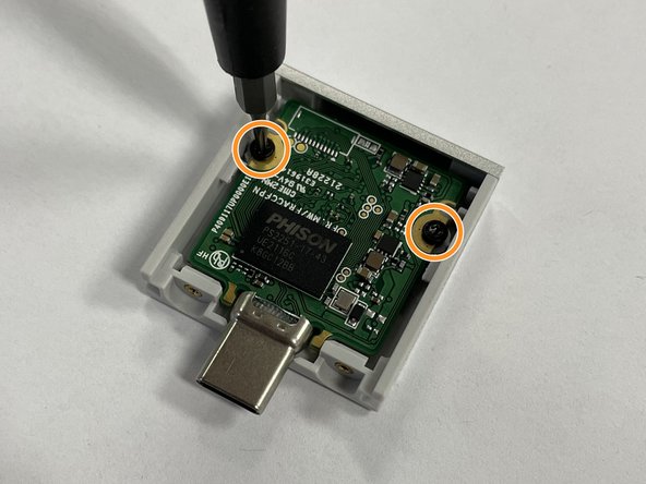
Using the T5 bit in your Framework Screwdriver, remove the two fasteners that hold the PCB in. This will let you get to the flash on the underside of the PCB.
-
-
-
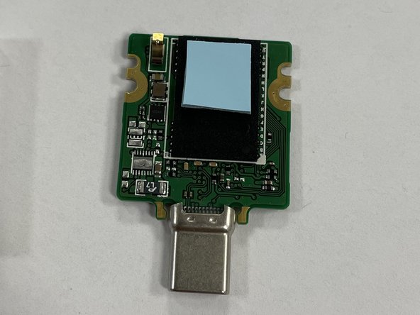
Remove the protective plastic from both sides of the thermal pad. Stick it to the top half of the flash package as shown in the image.
-
You can peel off the label that is on the flash package and stick it on the other side of the PCB if you'd like. It shouldn't substantially impact performance either way.
-
Your thermal pad may be a different size or color, but you should make sure that it is no more than 2mm thick, that it is soft and non-conductive, and that it is making contact between the black flash package and the aluminum cover when the PCB is re-installed.
-
-
-
Put the PCB back into the enclosure and fasten in back into place using the T5 bit in the Framework Screwdriver.
-
Slide the lid back on and fasten the two fasteners back into place using the T5 bit in the Framework Screwdriver.
-
Be extra careful to not overtighten these, as it is easy to accidentally crack the lid plastic.
-


Cancel: I did not complete this guide.
13 other people completed this guide.
4 Comments
Hi... this worked for a time, but today, it's started throttling again, what should I do?
GhostBuilder - Resolved on Release Reply
The pad's effect on the heat buildup is fairly impressive. A drop of 20 deg C puts it back to a more normal operating temperature during high write activity. I think that Framework should have sent these to users who purchased the affected units, instead of the user having to buy them. The cost of the pad is miniscule versus the shipping cost.
Is there a block of serial numbers for modules that were manufactured prior to the thermal pad modification?
Craig Lewis - Resolved on Release Reply