
Tools
Parts
-
-
If you are replacing the Webcam on the Framework 16, please navigate to that guide through this link.
-
If you are replacing the Webcam on the Framework 13, you can continue to the next step below.
-
-
-
Power off the Framework Laptop by navigating to the Windows icon on the bottom left and clicking on "Power" followed by "Shut down," or if on Linux, the equivalent action there.
-
-
-
Unplug your power cable from the USB-C Expansion Card in your Framework Laptop.
-
-
-
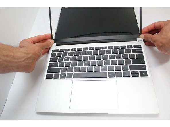
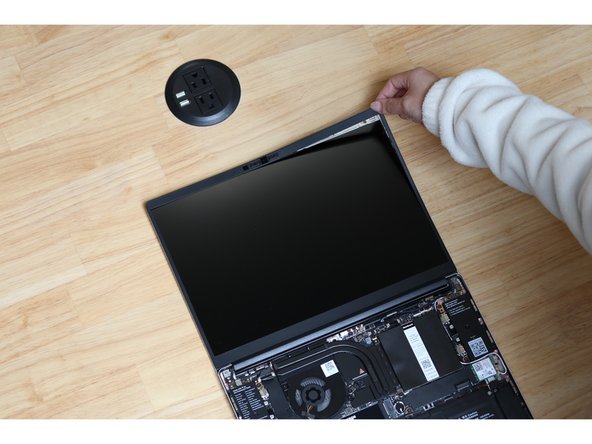
Open the Framework Laptop 180 degrees to remove the Bezel.
-
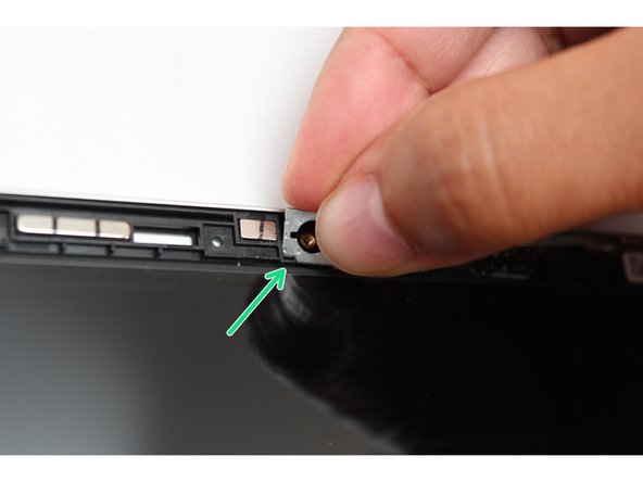
The Framework Bezel is attached by magnets so you will not require any tools to remove it. Just use your fingernail and pry the Bezel away from the display from one of the top corners of the Framework Laptop.
-
Once the Bezel starts peeling off towards the bottom of the Display, lift it up using caution. You might feel a little resistance due to the adhesive at the bottom of the display.
-
-
-
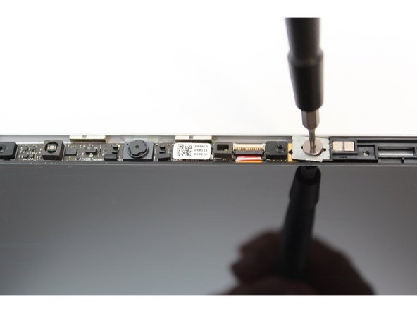
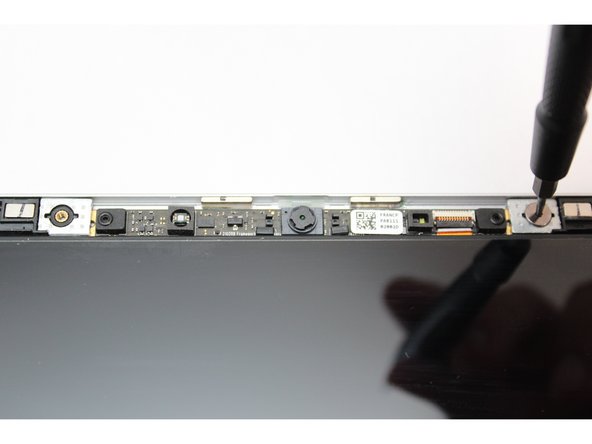
Using the T5 Bit in the Framework Screwdriver, unscrew the two fasteners connecting the Webcam Module to the Top Cover.
-
-
-
Remove the washers under the screws.
-
Tip: Use the bit on the Framework Screwdriver to lift the washers up since they are magnetic.
-
-
-
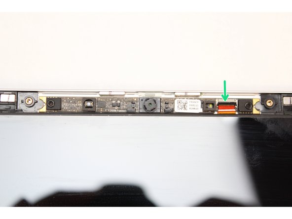
Using your fingernail or the spudger side of the Framework Screwdriver, flip up the black latch on the Webcam Cable to disconnect it.
-
-
-
Lift the module out of the cover by handling the module only by the edges.
-
The Webcam Module is now fully disconnected from the Top Cover.
-
-
-
Make sure the black latch on the connector is flipped up so that you can slide the Webcam Cable into the connector. Slide the cable straight in until the white line is almost at the edge of the connector.
-
Flip the black latch down to secure the cable in place.
-
-
-
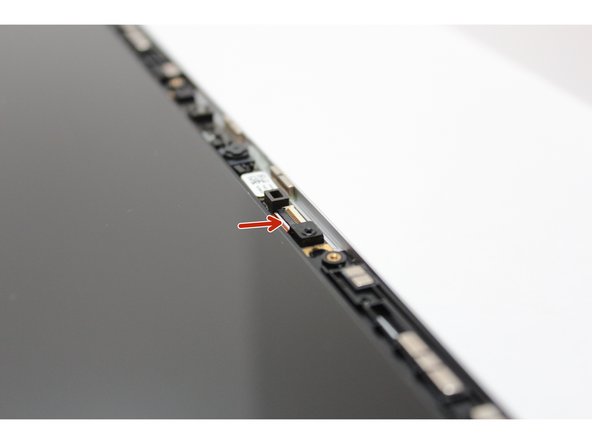
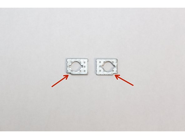
Find the two washers and orient them so that the notch on both washers are located at the bottom corner as indicated with the red arrows in the first image. These need to be aligned with the notch on the Top Cover.
-
Using your fingers, place the washers over the Webcam making sure the notch on the washer aligns with the notch on the Top Cover as indicated in the third image.
-
Place the second washer on the opposite side of the Webcam following the instructions above.
-
-
-
Using the T5 Bit in the Framework Screwdriver screw in both fasteners.
-
Be sure to not over tighten the fasteners.
-
-
-
The Webcam is now completely installed.
-
Open the Framework Laptop 180 degrees to attach the Bezel.
-
Align the corners of the Bezel to the display and place it down. The Bezel is attached by magnets and should easily click into place.
-
Make sure that all of the corners and edges of the Bezel are fully connected to the Top Cover. If the corners are not aligned. carefully lift up the part of the bezel and guide it into place.
-


- To purchase a Framework Laptop visit the Framework website
- Want to learn more about the Framework Laptop? Take a look at our blog
- If you have any questions or concerns, feel free to reach out to Framework Support
- To purchase a Framework Laptop visit the Framework website
- Want to learn more about the Framework Laptop? Take a look at our blog
- If you have any questions or concerns, feel free to reach out to Framework Support
Cancel: I did not complete this guide.
19 other people completed this guide.
5 Comments
I got to this page from the https://frame.work/gb/en/products/camera... page, this doesn't seem to be the correct guide for that.
Adam Astles - Open Reply
Clear and easy, just got my Gen2 webcam and it's great! Easy upgrade ;)
Giorgi Maghlakelidze - Resolved on Release Reply
You should also mention that the sliders for the switches on the bezel have tight alignment which requires nudging the sensor bar PCB between the torx fastened washers; it's easiest to fit the cover bezel and unclip the top magnets and bring it flush down over the PCB whilst testing the physical slider switches engage; which will allow slight nudges of the PCB bar to align prior to tightening the torx screws.
Joel Wirāmu Pauling - Resolved on Release Reply
Can you also mention the ALS (Ambient Light Sensor) Sensor in this guide; as it appears to be co-located with the same assembly.
I have just attempted a reseat of the flex connector; in the hopes that my non-functioning ALS would start to appear/init; but it did not work. I appear to have received a DOA ALS sensor on my Batch 1 AMD FW 13. Webcam works fine.
Joel Wirāmu Pauling - Resolved on Release Reply