
Tools
Parts
-
-
Power off the Framework Laptop by navigating to the Windows icon on the bottom left and clicking on "Power" followed by "Shut down," or if on Linux, the equivalent action there.
-
-
-
Unplug your power cable from the USB-C Expansion Card in your Framework Laptop.
-
-
-
Close the lid on your Framework Laptop and place it upside down on a soft, non-marring surface, such as the bag that it shipped in.
-
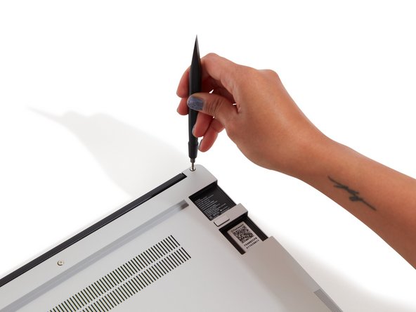
Using the T5 bit in the Framework Screwdriver, unscrew the 5 fasteners on the Bottom Cover. These fasteners will remain attached in the Bottom Cover so that you do not lose them.
-
The fastener on the bottom left (circled in red) will not unscrew as far as the others, as it is acting as a lifter for the Input Cover.
-
You'll hear this fastener start clicking as you rotate when it is unscrewed far enough.
-
Do not use a powered tool for these steps, as this will likely result in damage to the fasteners.
-
-
-
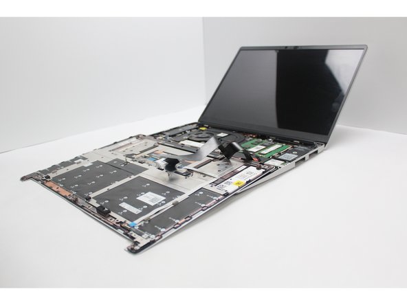
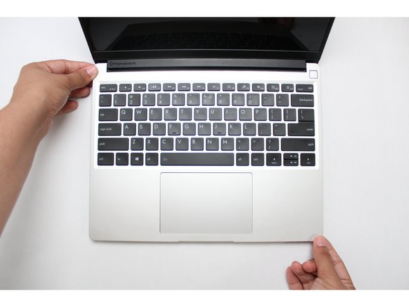
Flip the Framework Laptop back over and open the lid to around 120 degrees.
-
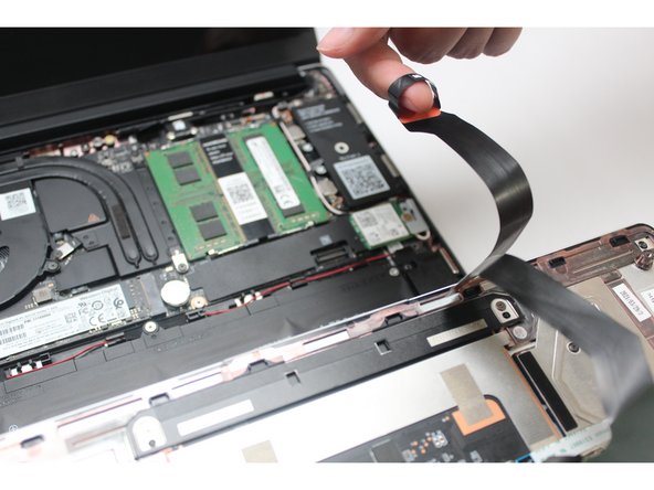
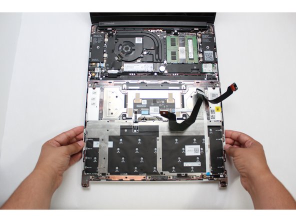
Important: Pull the Input Cover off carefully as it is still attached to the Mainboard via the Touchpad Cable. You don't need to disconnect this cable to do most repairs. You can just flip the Input Cover over. If you do want to disconnect it though, make sure to disconnect the Mainboard side using the finger loop over the orange label.
-
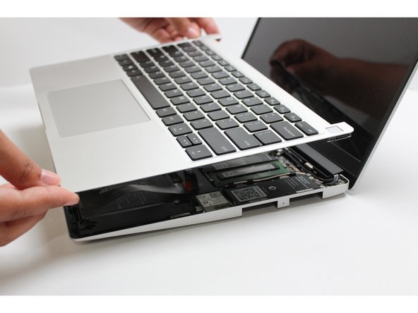
The bottom right corner of the Input Cover lifts up when the five fasteners are properly unscrewed from the previous step. You should not have to use any excessive force to remove the Input Cover.
-
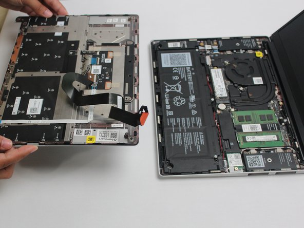
Carefully lift the cover up from the bottom right corner. If you need to, you can use the spudger end of the Framework Screwdriver to lift it as well. Lift the Input Cover off the Mainboard, flip it over (keyboard side down), and place it about halfway on the Bottom Cover.
-
Be sure not to put too much force on the Touchpad Cable when doing this.
-
If the LEDs on the left and right sides of the system are flashing red when you lift off the cover, it means the system is still powered on. Make sure your power cable isn't plugged in and that you have shut down correctly.
-
Note that it may take up to 30 seconds after shutting down for the system to fully power off. Wait until the LEDs stop flashing before proceeding.
-
You should keep the Battery connector plugged in unless you need to replace the Battery, Mainboard, or Speakers. This connector is easy to accidentally damage, so it's better to not handle it.
-
-
-
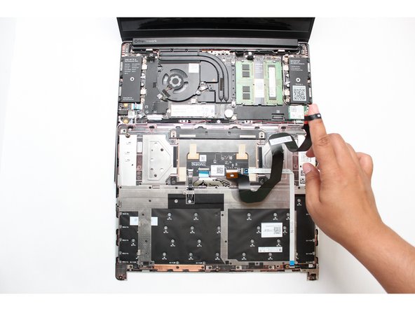
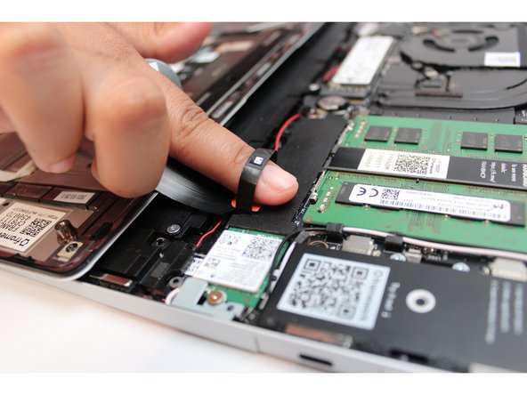
Disconnect the Touchpad Cable from the Mainboard by inserting your finger into the loop and pull directly upward using a slight amount of force.
-
Once the Touchpad Cable is disconnected, remove the Input Cover away from the Mainboard.
-
-
-
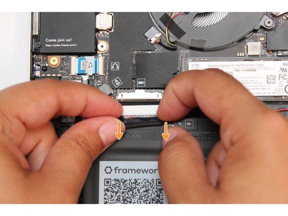
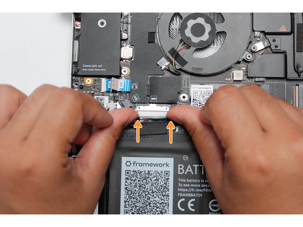
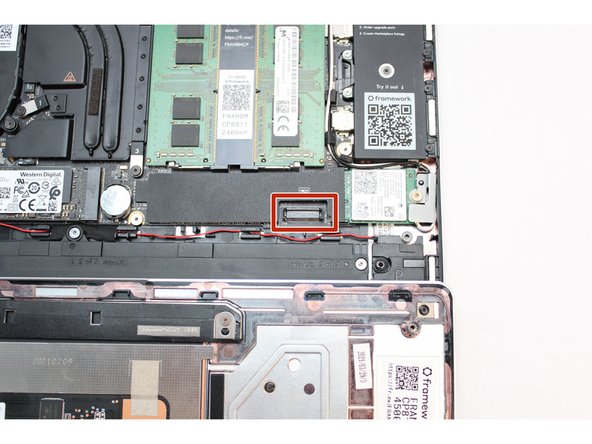
Be extremely careful when sliding the Battery connector out, as it is very easy to accidently bend the pins. Make sure to slide straight down, and avoid letting the connector twist or bend.
-
Gently disconnect the Battery by gripping the connector edges with both fingers and slide the connector straight down from the socket.
-
-
-
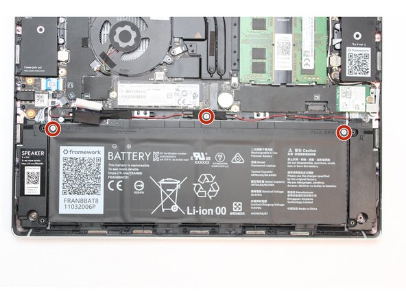
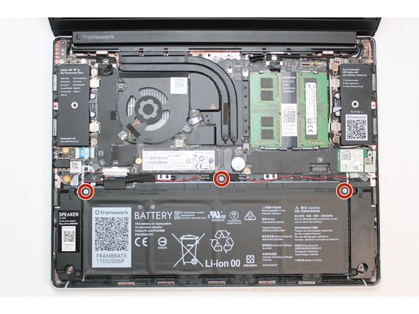
Using the T5 bit in the Framework Screwdriver, unscrew the three fasteners on the battery.
-
Note: The screws will come loose after a few revolutions however they will remain attached to the battery.
-
-
-
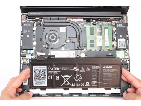
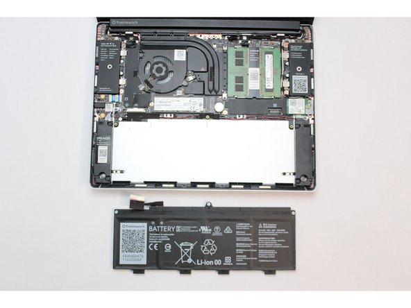
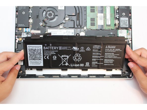
Use your fingernail to gently Lift the battery up and away from the bottom cover. Carefully lift it out and keep it in a safe place.
-
Warning: Handle the battery by the plastic frame, make sure not to bend, scratch, cut, or puncture it, and keep it away from heat sources
-
-
-
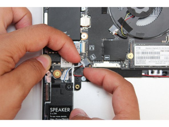
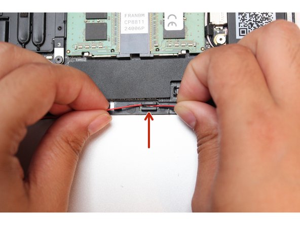
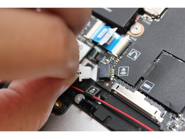
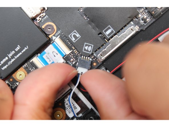
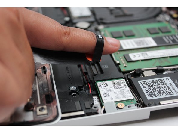
Using your fingernails disconnect the speaker connector from the Mainboard by gripping the edges of the connector and pulling straight out.
-
-
-
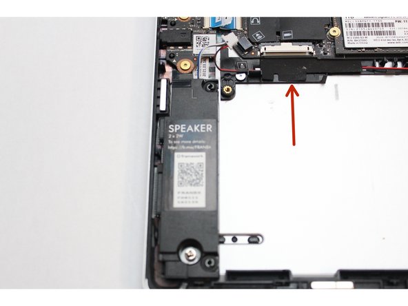
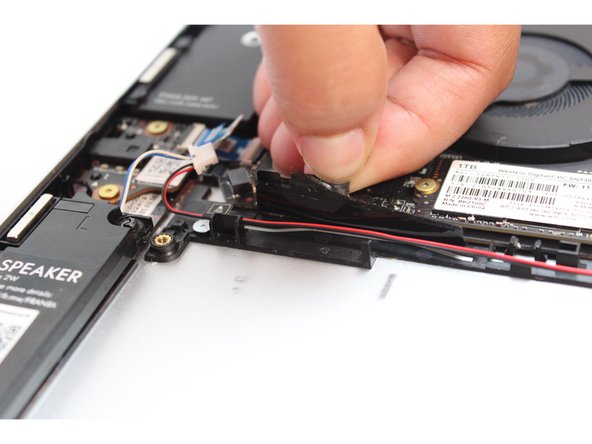
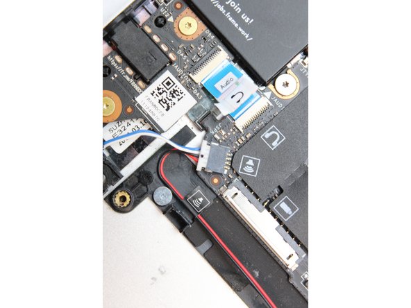
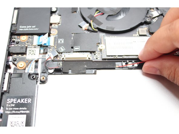
Locate one of two pieces of black tape and carefully peel it back to reveal the black and red speaker wires.
-
Do not completely remove the tape from the Bottom Cover, peel it back just enough to reveal the wires.
-
-
-
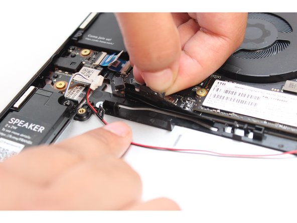
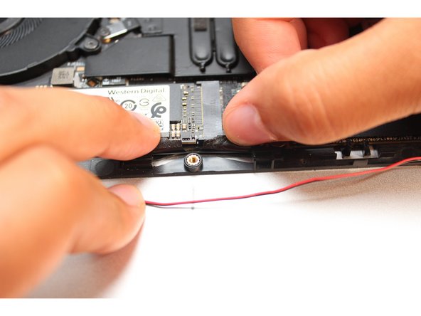
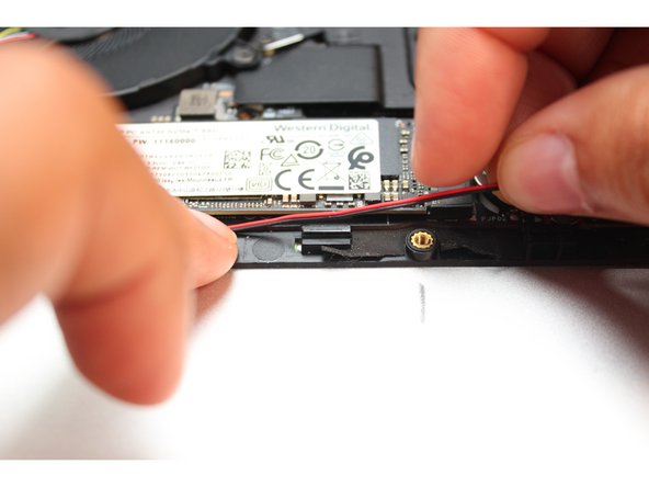
Locate the other piece of black tape and carefully peel it back to reveal the black and red speaker wires.
-
Do not completely remove the tape from the Bottom Cover, peel it back just enough to reveal the wires.
-
-
-
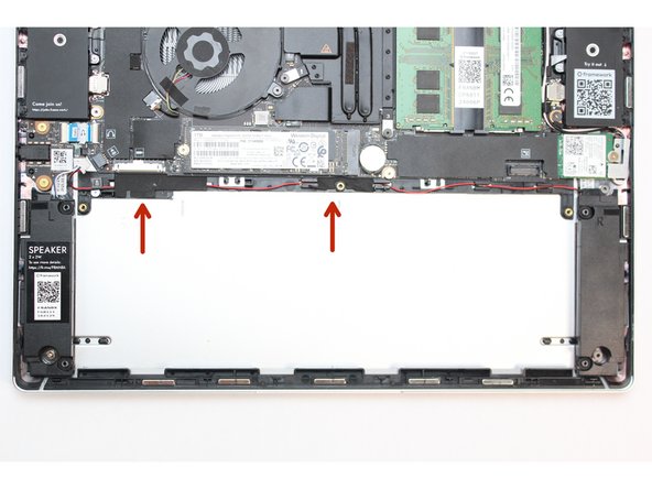
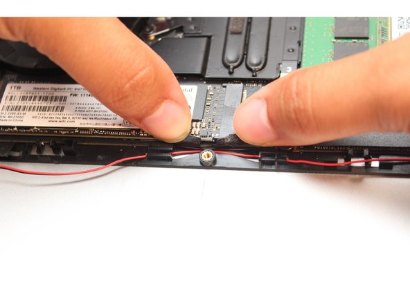
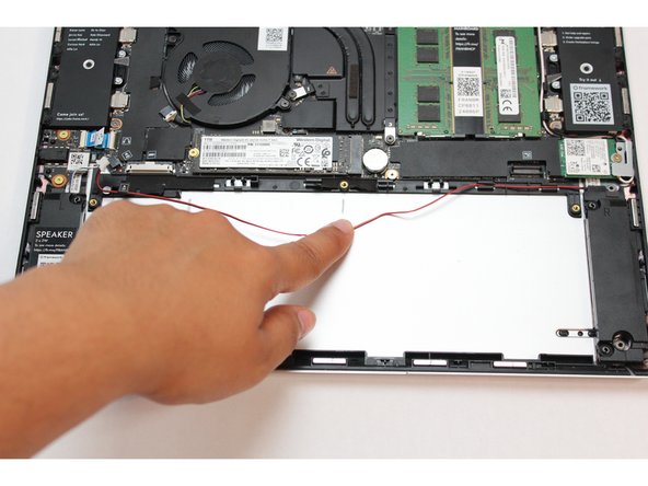
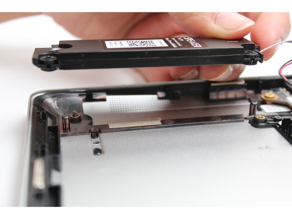
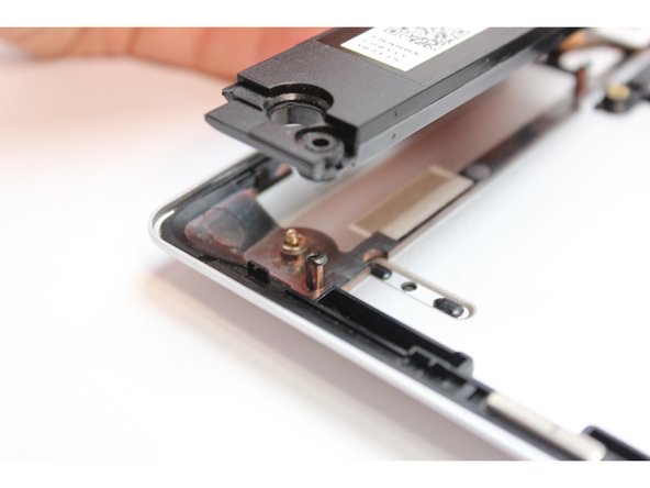
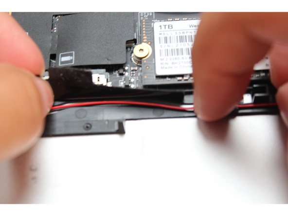
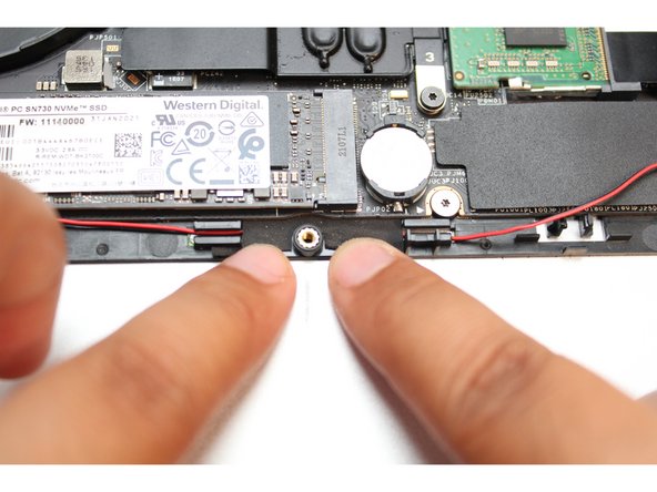
Carefully lift the wires out of the wire routers and very gently pull the wires down so that they are free.
-
-
-
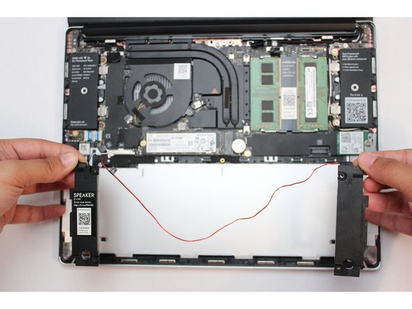
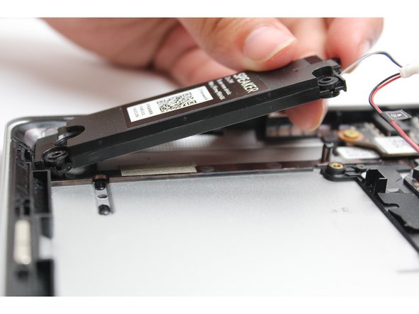
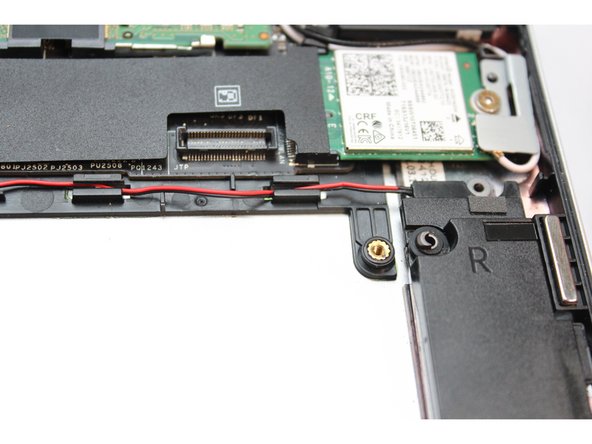
The speakers are now disconnected. You can lift both the left and right speaker out of the Bottom Cover.
-
-
-
Place both the Left and Right speakers in their respective spaces on the Bottom Cover by aligning the pegs with the rubber gaskets.
-
Note: You'll notice an L and R on both speakers to help you figure out the proper placement.
-
-
-
Using your fingers and a slight amount of force, insert the speaker connector straight into the Mainboard.
-
-
-
Peel the black tape back and place the wires under it. Cover the wires with same tape.
-
-
-
Place the wires into the wire router next to the other piece of black tape. Peel the tape back and place the wires under it. Cover the wires with same tape.
-
-
-
Route the wires through each of the wire routers. You can use your fingernail to secure the wires in place.
-
The Speakers are now fully installed.
-
Make sure the Speaker is not touching the white or black antenna from the WiFi Module.
-
-
-
Using your fingertips, gently handle the Framework battery with the plastic frame, slide it into the Bottom Cover. Use the first image as a reference.
-
Warning: Handle the battery by the plastic frame, make sure not to bend, scratch, cut, or puncture it, and keep it away from heat sources.
-
-
-
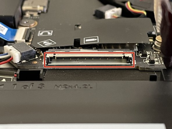
Before plugging the Battery connector back in, double check the pins on the Battery receptacle on the Mainboard, and make sure none of them look bent.
-
Don't plug the Battery connector in if pins look bent, as that will bend them even further. Reach out to Framework Support for guidance.
-
If you feel resistance when plugging in the Battery connector, stop, slide the connector back out, and make sure that no pins are being bent.
-
Carefully slide the Battery connector back into the mainboard, gripping both edges of the connector and sliding in straight without letting the connector twist or bend.
-
-
-
Using the T5 bit in the Framework Screwdriver, screw the three fasteners into place.
-
-
-
Gently place the Input Cover keyboard side down on the Bottom Cover as indicated on the image. The cover should be about an inch and a half away from the bottom of the Mainboard so that you can comfortably install the Touchpad Cable.
-
Note: The orientation of the Input Cover matters. Study the first image in this step to ensure you are properly attaching the cover.
-
Locate the loop on the end of the Touchpad Cable and insert your finger into it.
-
-
-
Using slight force, connect the Touchpad Cable by aligning it to the socket on Mainboard. You should hear it click into place once properly connected.
-
-
-
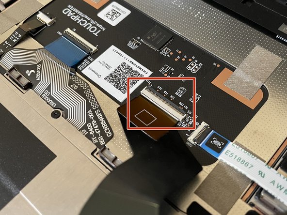
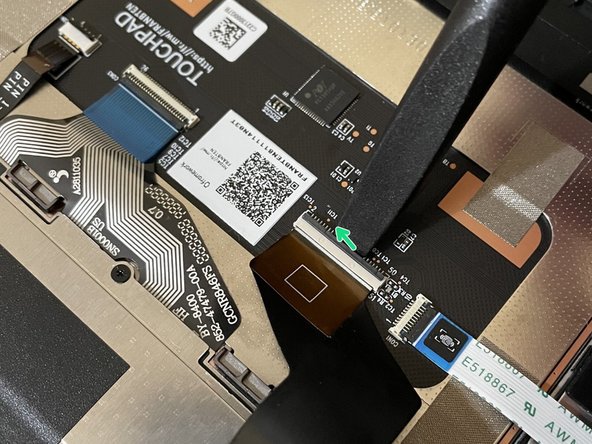
Before closing up the laptop, make sure that the Touchpad end of the Touchpad Cable is fully seated in the receptacle.
-
The cable should be inserted far enough that the white line almost touches the receptacle.
-
If it is not inserted far enough, you'll need to flip up the black latch on the other side of the connector, slide the cable in further, and then close the black latch again.
-
-
-
Once the Touchpad cable is secured to the Mainboard, flip the Input Cover over the Bottom Cover so that the keyboard is facing up and attach it to the Bottom Cover by aligning the top and bottom edges of both covers.
-
Tip: The covers are magnetic and should fit into one another easily. If you feel any resistance simply lift the Input Cover up and try again.
-
-
-
Close the Framework Laptop and turn it upside down to reveal the empty Expansion Card bays and fasteners on the Bottom Cover.
-
Using the T5 bit in the Framework Screwdriver, screw all 5 fasteners back into the Bottom Cover.
-
Be sure to not over-tighten the fasteners.
-


- To purchase a Framework Laptop visit the Framework website.
- Want to learn more about the Framework Laptop? Take a look at our blog.
- If you have any questions or concerns, feel free to reach out to Framework Support.
- To purchase a Framework Laptop visit the Framework website.
- Want to learn more about the Framework Laptop? Take a look at our blog.
- If you have any questions or concerns, feel free to reach out to Framework Support.
Cancel: I did not complete this guide.
17 other people completed this guide.
7 Comments
Replaced my speakers on my FW13 intel 11th gen (batch 5). The new speakers are loud and clear but lack some bass. This guide was super detailed, fun and easy to follow along.
Emil Larsson - Resolved on Release Reply
This speaker replacement guide is incredibly detailed and easy to follow. It was exactly what I needed to successfully replace my laptop speakers. Thank you for providing such clear instructions!
Bajrang Waghmare - Resolved on Release Reply
The Speaker Replacement Guide is very detailed and easy to follow. It's great to have such a clear resource for DIY repairs—this information is definitely useful for anyone looking to replace their laptop speakers.
Shiv Teckchandani - Resolved on Release Reply
The step-by-step instructions in this speaker replacement guide are incredibly clear and practical. This information is very useful for anyone looking to perform their own laptop repairs.
Shiv Teckchandani - Resolved on Release Reply
This speaker replacement guide is incredibly clear and easy to follow. It provided the exact steps I needed to successfully replace my laptop's speakers.
Shiv Teckchandani - Resolved on Release Reply