
Introduction
Sponges included in the Kit;
- WLAN Sponge (Sponge 1) - (5.25mm x 21.5mm)
- Above M.2 SSD (align with copper tube shape) - (Sponge 2) - (16.75mm x 66.5mm)
- Just above CPU (align with copper tube shape) - (Sponge 3) - (19.129.0mm x 67.65mm)
- Above RAM (Sponge 4) - (11.75mm x 48.25mm)
- Below the right fan (align with copper tube edge) - (Sponge 5) - (11.75mm x 24.50mm)
Tools
Parts
-
-
In order to remove the Input Modules from the Framework Laptop 16, begin by opening the Input Deck Latches on each side of the Laptop.
-
When the latches are open you can see the red printed on the latch.
-
-
-
To remove the Touchpad Spacers, slide them down and then they will lift away easily.
-
If there is resistance, make sure that the Input Deck Latches are open (see previous step).
-
-
-
After removing the Spacers, the Touchpad module can be removed in the same way. Gently slide it downwards from both sides and then lift away as shown.
-
-
-
To remove the Keyboard lift from the bottom using the pull tabs, and once lifted up the Keyboard module should lift out without resistance.
-
If your pull tabs are no longer attached, you can carefully use the spudger side of the Framework Screwdriver to lift the module away.
-
-
-
Remove your Input Modules or Spacers in the same way as the Keyboard, lifting from the bottom using the pull tabs as shown.
-
-
-
This cable is labeled with the Number 1 to indicate that it should be disconnected before loosening the Mid Plate Fasteners.
-
It is important to disconnect this cable before removing the Mid Plate as leaving it attached could damage the cable.
-
-
-
Using the T5 bit in the Framework Screwdriver unscrew the 16 captive fasteners attaching the Mid Plate to the Bottom Cover. These are numbered from 2-17 (since the Mid Plate Cable is number 1)
-
These fasteners are captive, meaning they will remain attached to the Mid Plate when fully loosened.
-
Do not use powered tools for this step as this risks damage to the fasteners, as with all fasteners in the Framework Laptop 16 these can be easily loosened using the included Framework Screwdriver
-
-
-
Carefully lift the Mid Plate away from the Bottom Cover and set it aside.
-
If the Mid Plate seems stuck, check the fasteners are all loosened, there should be little resistance.
-
-
-
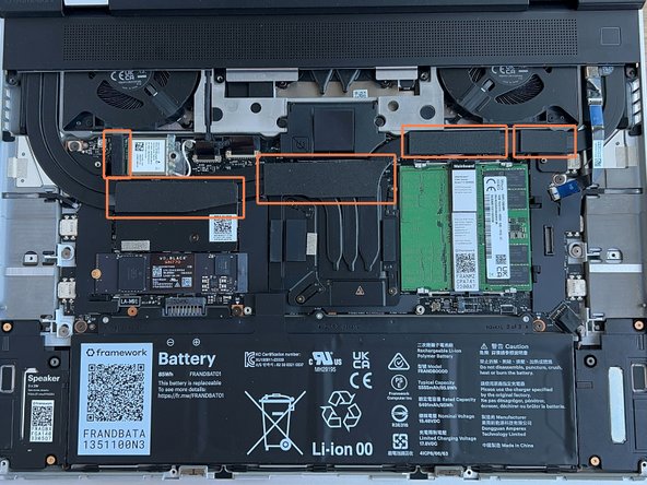
There are 5 total sponges. Arrange your sponges like this from Left to Right. This is the same order we will be applying them.
-
Here is an image of where they will sit once their backing is removed.
-
-
-
First sponge to apply is the one for the WLAN module, the sponge is roughly (5.25mm x 21.5mm) in size and goes on top of the plastic WLAN connector.
-
Remove the clear paper backing of the sponge to reveal the sticky side.
-
Now place the sticky side against the top of the plastic WLAN connector.
-
This as at the base where the Wi-Fi card is plugged in.
-
-
-
Second sponge will go above the M.2 slot and align with the copper plate shape. The sponge for this is roughly (16.75mm x 66.5mm) in size and matches the shape you are placing it onto.
-
Remove the white paper backing of the sponge to reveal the sticky side.
-
Now place the sticky side against the plate matching the shape.
-
This the copper plate between the Wi-Fi card and the M.2 slot.
-
-
-
Third sponge will go on top of the copper pipes above the CPU. The size of this sponge at its widest points is roughly (19.1mm x 67.65mm) and matches the shape you are placing it onto.
-
Remove the white paper backing of the sponge to reveal the sticky side.
-
Now place the sticky side against the pipes matching the shape.
-
This is directly below the below the interposer door.
-
-
-
Fourth sponge will go on top of the copper pipe above the RAM. The sponge for this is roughly (11.75mm x 48.25mm).
-
Remove the white paper backing of the sponge to reveal the sticky side.
-
Now place the sticky side against the pipe making sure the right edge of the sponge meets the edge of the black standoff.
-
-
-
Fifth and final sponge will go to the right of the sponge you just put down. The sponge for this is roughly (11.75mm x 24.50mm).
-
Remove the white paper backing of the sponge to reveal the sticky side.
-
Now place the sticky side against the pipe making sure the left edge aligns with the edge of the plate below.
-
Important Note: When placing this one down, make sure you do not accidentally stick it to the ribbon cable on the right of it.
-
-
-
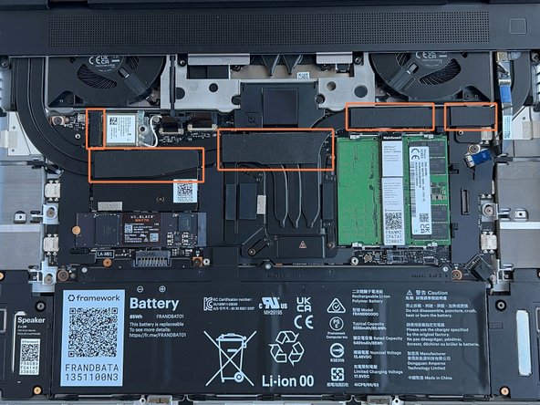
With all five of the sponges applied, it should look like this!
-
-
-
Place the Mid Plate onto the system, aligning the holes in the Mid Plate with the two guide posts.
-
These posts are on the left side and the right side, immediately above the speakers on both sides.
-
Take extra time to make sure it's sitting level/ flush.
-
-
-
Using the pull tab, gently press the Mid Plate connector down to connect it to the Mainboard.
-
Carefully align, then firmly press in the mid plate connector cable.
-
-
-
Using the T5 bit in the Framework Screwdriver tighten the Mid Plate fasteners.
-
Before gently tightening the screws, double check that the mid plate is aligned correctly as shown in previous step.
-
These fasteners are labelled 2-17 (since the Mid Plate cable is number 1) and should be tightened in order, starting with 2 and ending with 17.
-
Do not overtighten these fasteners, and we recommend against the use of powered tools for these or any other fasteners on the Framework Laptop 16.
-
-
-
Next install, two Spacer Modules, an LED Matrix, a Numpad, an RGB Macropad, or whichever other combination of two Small or one Medium sized Input Module you have.
-
Slide these in at an angle and lower into place, the same way the Keyboard was installed.
-
Whichever Input modules you chose to install, you should have no empty spaces in the top row before proceeding to the next step.
-
-
-
Please see our guide here on possible Input Module configurations.
-
Holding from the pull tabs at the bottom of the Keyboard module, line it up with the dashed guide lines printed on the Mid Plate. Note that you can align a Keyboard so that it is either along the left edge, the right edge, or centered. With the Keyboard held at a 20 degree angle, slide it up into place.
-
The notches along the top of the Keyboard will fit into the corresponding alignment guides under the Ventilation Plate.
-
Lower the Keyboard gently into place, it should snap in place magnetically and sit flat.
-
Ensure that the pins in the Mid Plate to the left and right of the Input Module Connector align into the corresponding holes in the Keyboard module.
-
-
-
Place the Touchpad Module flat, slightly below the Keyboard as shown.
-
Like the Keyboard, you can confirm it is properly aligned by lining it up to the dashed lines on the Mid Plate.
-
Applying gentle downward pressure to keep the Touchpad module flat, slide it up into place.
-
Remember that the Input Deck Latches should still be open at this point, otherwise the Touchpad Module won't slide on.
-
The Touchpad Module can be installed either directly below the Keyboard or offset by one space to the right. For example, the Keyboard can have the Touchpad below it, or the Keyboard can be left-aligned while the Touchpad is centered.
-
-
-
Just like installing the Touchpad module, place the Touchpad Spacers flat on the Input Deck, slightly below the Keyboard or Spacers above.
-
Applying gentle pressure, slide the Touch Module Spacers into place.
-
With the Touchpad Module Spacers installed there should now be no empty spaces on the Input Deck.
-
-
-
Once all Input Modules are installed, close both Input Deck Latches to secure them in place.
-
Cancel: I did not complete this guide.
7 other people completed this guide.