Introduction
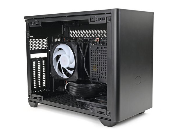
Follow this guide to install a Framework Desktop Mainboard into a Mini-ITX case.
The Framework Desktop Mainboard is compatible with a standard Mini-ITX case, ATX Power Supply, and 120mm CPU Fan. For detailed parts compatibility, click here.
For information on the Front Panel IO Connectors, click here.
This guide only shows installing the Mainboard and assumes that a power supply and antenna module are already installed.
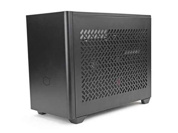
This guide features a Cooler Master NR200 case, but the procedure is identical across most Mini-ITX cases.
Parts
No parts specified.
-
-
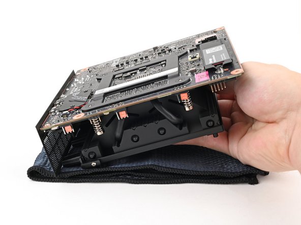
Depending on your case, some components on the bottom of your Mainboard might be inaccessible after you install it.
-
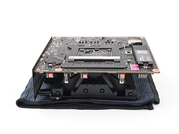
The next four steps show how to install the secondary storage before installing the Mainboard; however, you may need to install other components, such as the Wi-Fi module.
-
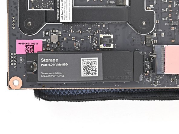
Place the Mainboard on your work surface with its heatsink resting on a soft, clean cloth.
-
-
-
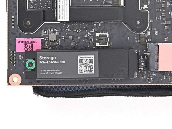
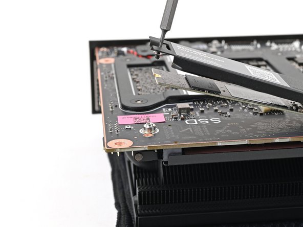
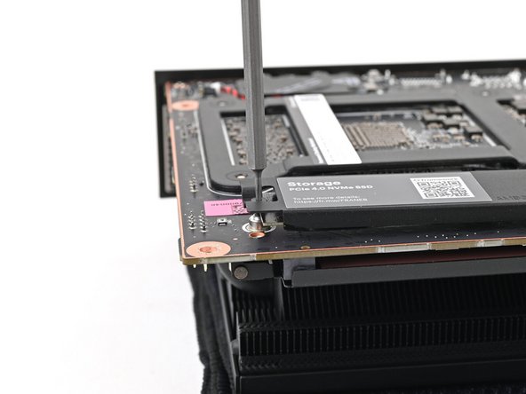
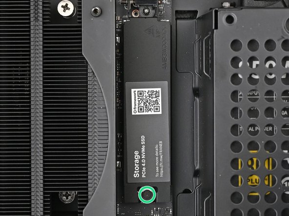
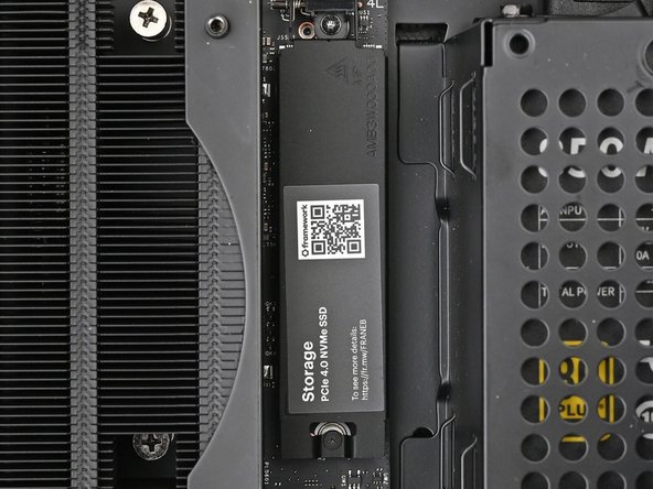
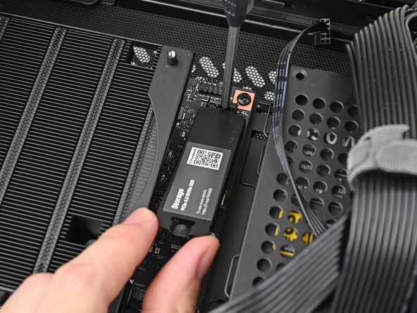
Use your Framework Desktop Screwdriver to loosen the captive T5 Torx screw securing the secondary storage.
-
The heat spreader will pop up to an angle when its screw is fully loosened.
-
-
-
If your SSD comes with a pre-installed heat spreader, follow the next two steps. Otherwise skip to Step 5.
-
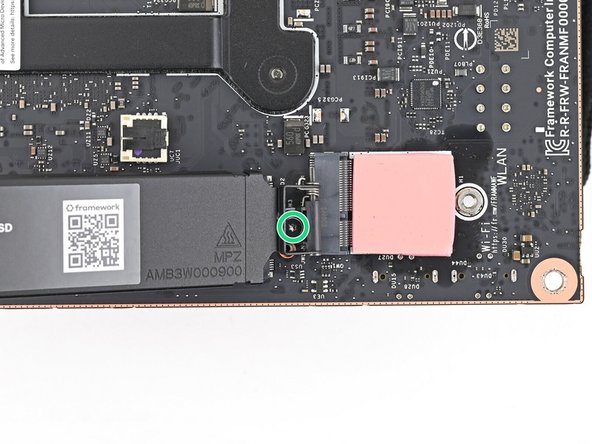
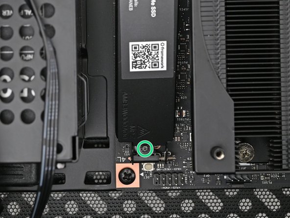
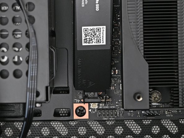
While securing the secondary storage heat spreader with one hand, use your Framework Desktop Screwdriver to remove the 4.5 mm‑long T5 Torx screw securing it.
-
-
-
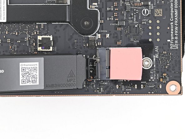
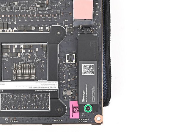
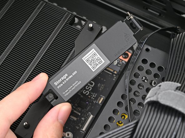
Lift the secondary storage heat spreader out of the Desktop and remove it.
-
Follow the guide normally, making sure to ignore instructions that involve the secondary heat spreader.
-
-
-
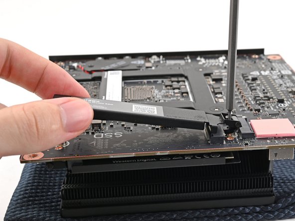
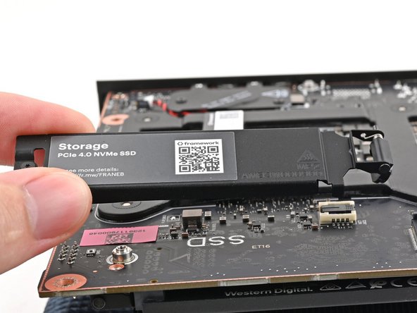
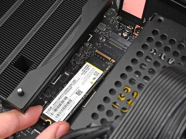
Hold the SSD by its edges. Don't touch the gold contacts with your fingers. If you do, wipe the contacts with a clean, lint-free cloth to remove any finger oils.
-
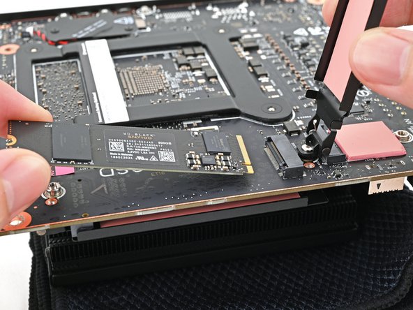
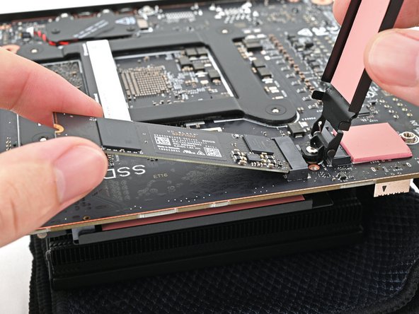
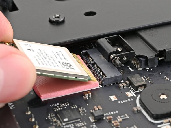
While holding the heat spreader upright, align the SSD's gold contacts with its socket.
-
Insert the SSD into the socket at a shallow angle. The gold contacts should be mostly covered by the socket.
-
The SSD fits into the socket in one orientation. If it doesn't feel like it fits, try flipping the module.
-
-
-
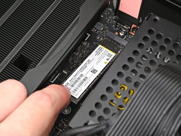
Insert your Framework Desktop Screwdriver into the captive screw on the secondary storage heat spreader and press it flat to the Mainboard.
-
Tighten the screw securing the secondary storage.
-
-
-
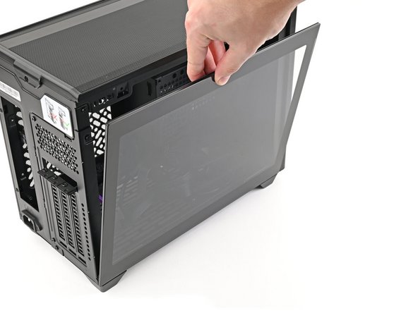
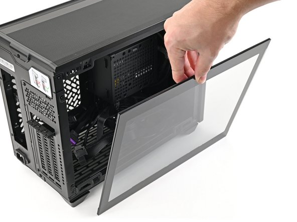
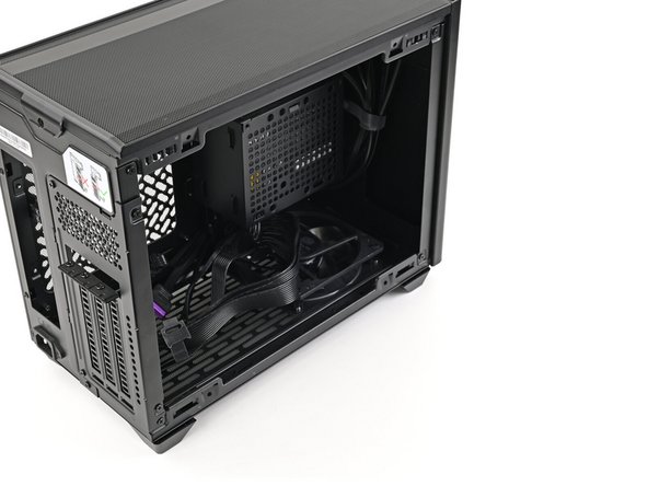
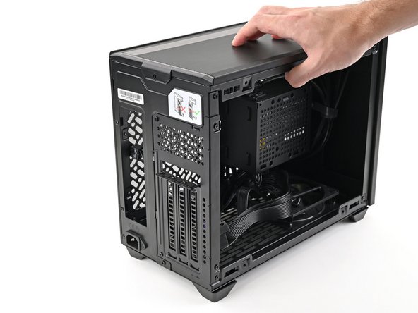
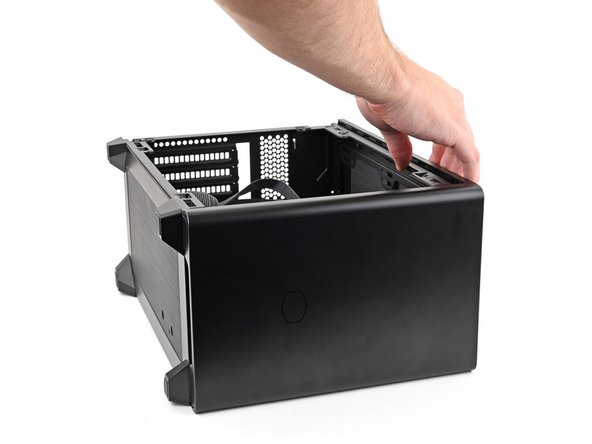
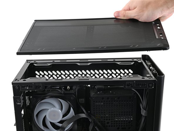
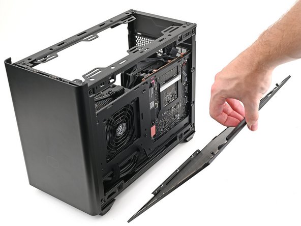
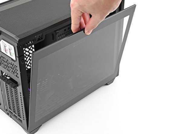
Remove the side panel from your case so you can access the cutout for the Mainboard.
-
-
-
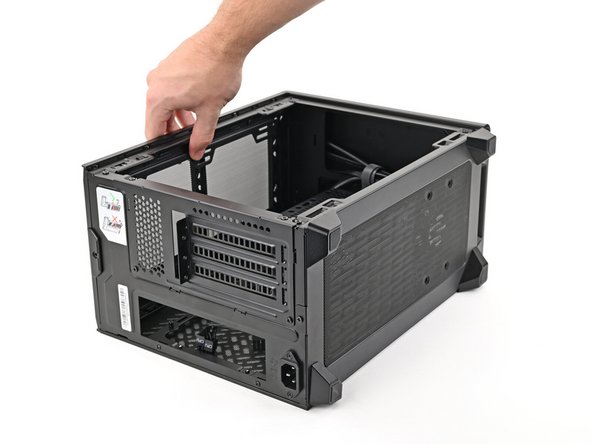
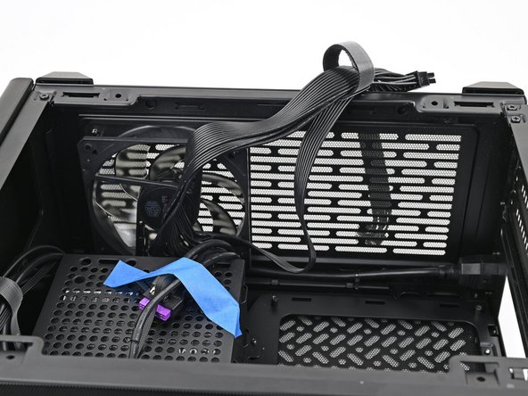
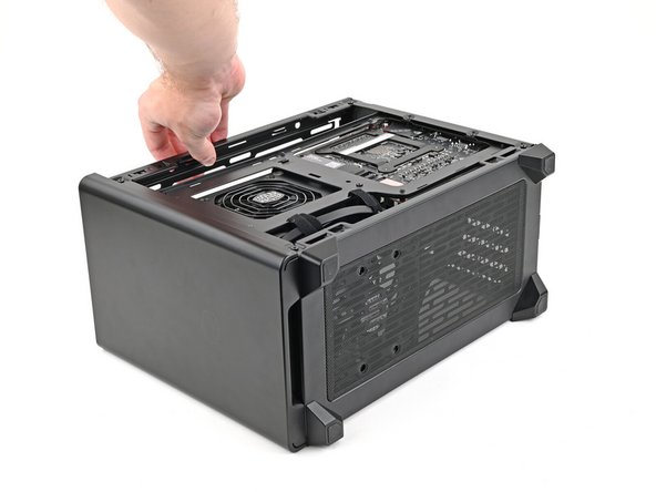
Lay the case on its side.
-
-
-
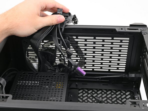
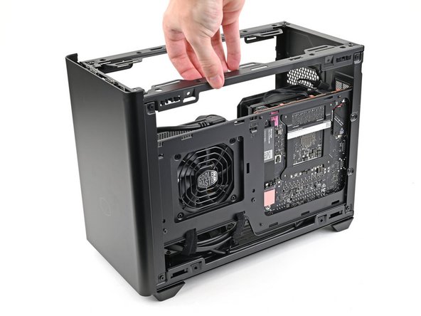
Move the cables out of the way of the Mainboard cutout.
-
Optionally, you can use tape with light adhesive, like painter's tape, to keep the cables out of the way.
-
-
-
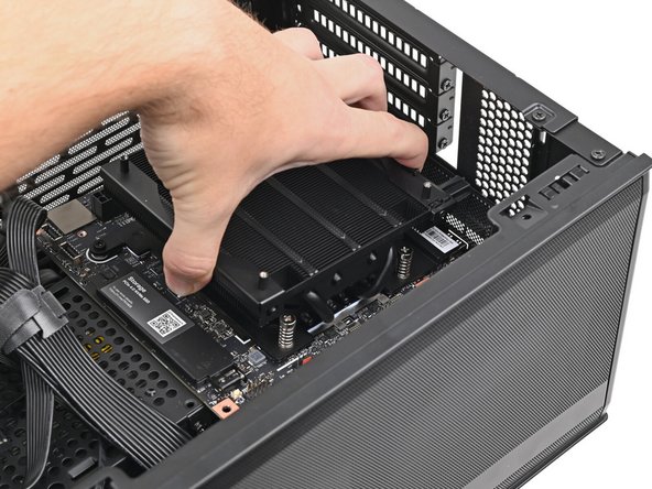
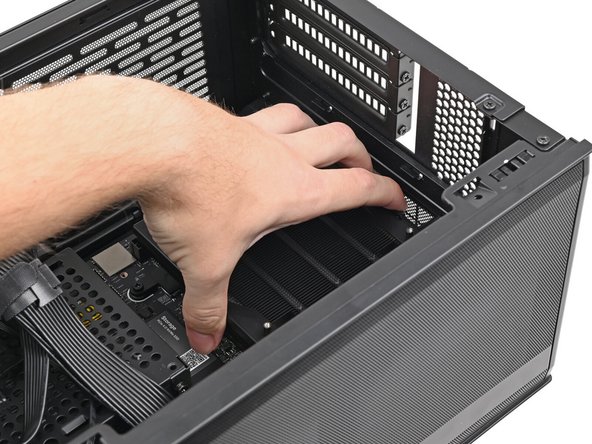
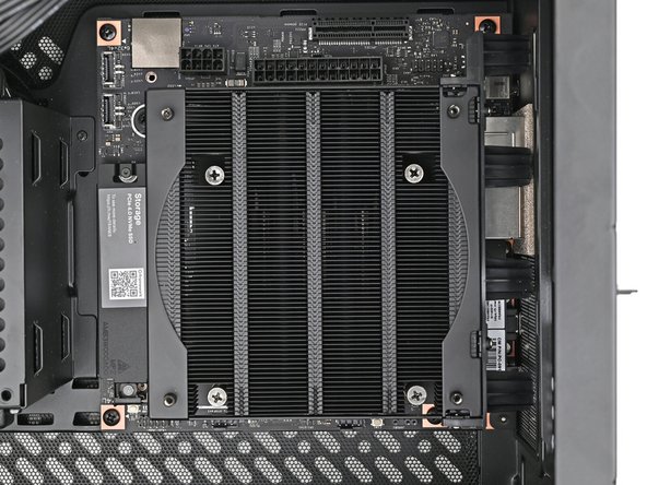
Grip the Mainboard by the heatsink and place it into its cutout, making sure the ports aligns with its slot in the case.
-
When handling the Heatsink, grab from the left and right sides (sides facing Front Panel & Back IO) as to prevent bent fins and possible damage to the Heatsink.
-
You may need to move the Mainboard around in its cutout until it rests properly on its screw posts.
-
-
-
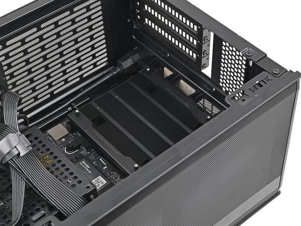
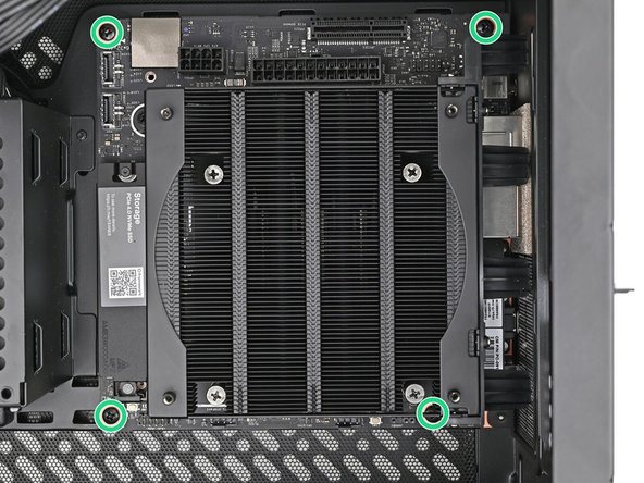
Use your Framework Desktop Screwdriver to install the four 8.2 mm‑long Phillips screws securing the Mainboard.
-
-
-
Use your Framework Desktop Screwdriver to loosen the captive T5 Torx screw securing the primary storage.
-
The heat spreader will pop up to an angle when its screw is fully loosened.
-
-
-
If your SSD comes with a pre-installed heat spreader, follow the next two steps. Otherwise skip to Step 15.
-
While securing the primary storage heat spreader with one hand, use your Framework Desktop Screwdriver to remove the 4.5 mm‑long T5 Torx screw securing it.
-
-
-
Lift the primary storage heat spreader out of the desktop and remove it.
-
Follow the guide normally, making sure to ignore instructions that involve the primary storage heat spreader.
-
-
-
Hold the SSD by its edges. Don't touch the gold contacts with your fingers. If you do, wipe the contacts with a clean, lint-free cloth to remove any finger oils.
-
While holding the heat spreader upright, align the SSD's gold contacts with its socket.
-
Insert the SSD into the socket at a shallow angle. The gold contacts should mostly be covered by the socket.
-
The SSD fits into the socket in one orientation. If it doesn't feel like it fits, try flipping the module.
-
Lay the heat spreader back onto the SSD.
-
-
-
Insert your Framework Desktop Screwdriver into the captive screw on the primary storage heat spreader and press it flat to the Mainboard.
-
Tighten the screw securing the primary storage.
-
-
-
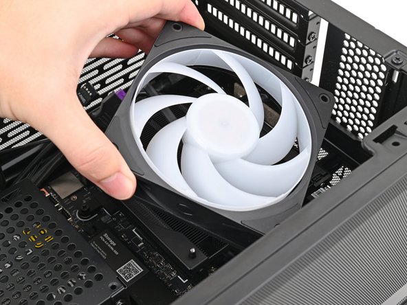
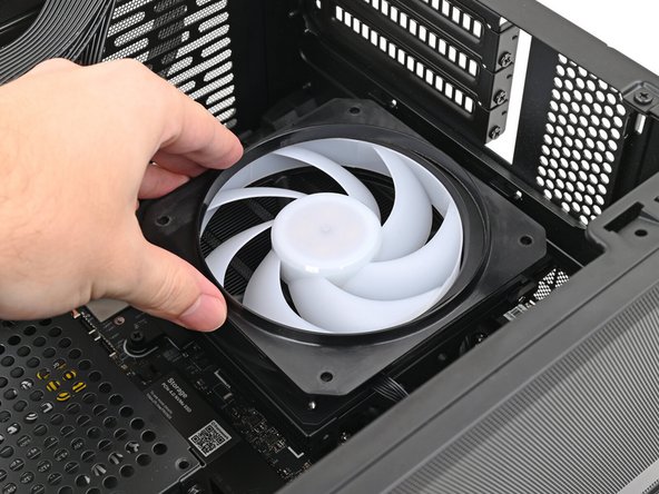
Orient the fan so its label is facing downward and the cable(s) are pointing towards their sockets on the Mainboard.
-
Depending on your fan, you may have one or two cables.
-
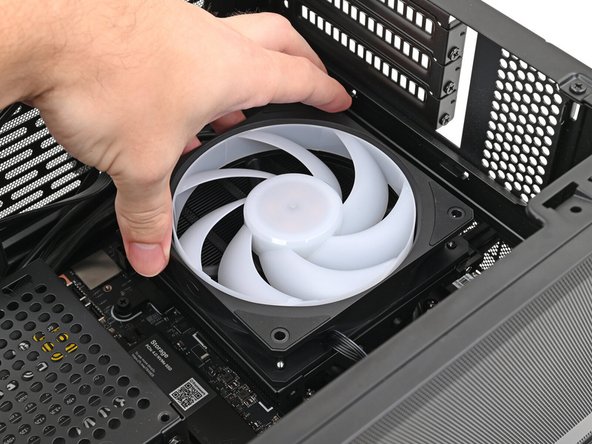
Lay the fan on top of the heatsink.
-
If your fan has an arrow indicating airflow direction, make sure it's pointed towards the heatsink.
-
If you're using a different fan, orient it such that the fan is blowing towards the heatsink, not away.
-
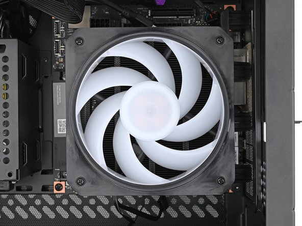
Lay the fan duct on top of the fan with the lip facing upward.
-
Align the screw holes on the fan duct with the ones on the fan.
-
-
-
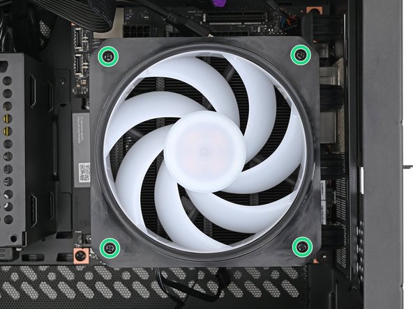
Use your Framework Desktop Screwdriver to install the four 27.3 mm‑long Phillips screws securing the CPU fan and fan duct.
-
-
-
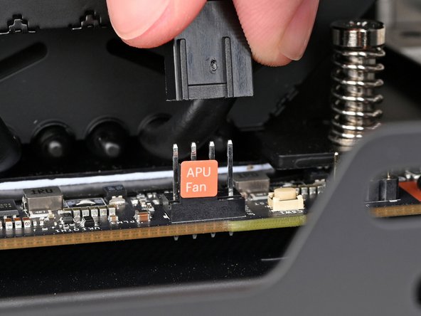
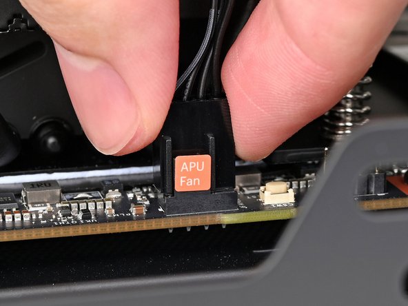
Slide the main fan cable over the four-pronged connector labeled "APU Fan," making sure the orange label slots between the vertical lines.
-
-
-
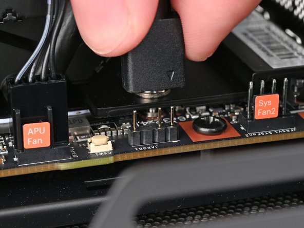
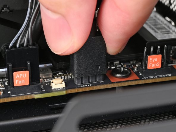
If you aren't using an RGB fan, then skip this step.
-
Use your fingers to slide the RGB cable over the three pronged connector located to the right of the "APU Fan" connector.
-
-
-
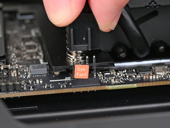
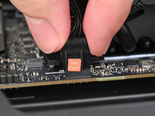
Follow this step to connect an additional fan. Otherwise, skip it.
-
Slide the cable over the four-pronged connector labeled "Sys Fan1," making sure the orange label slots between the vertical lines.
-
-
-
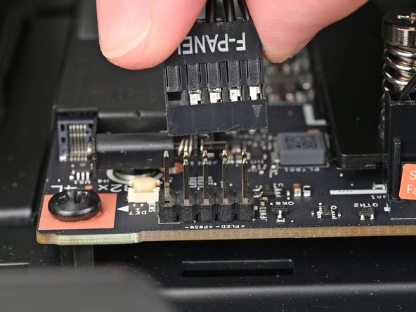
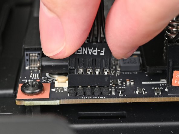
Slide the front panel header cable into its 9-pin connector underneath the primary storage.
-
-
-
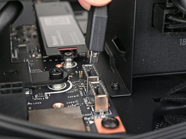
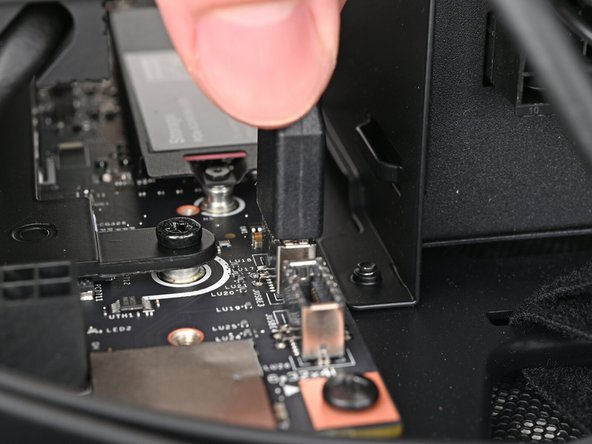
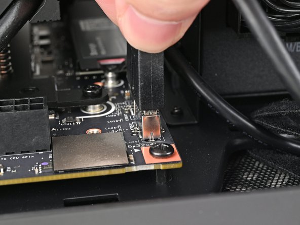
Slide the USB port cable into one of the USB Type-E 20-pin sockets above the primary storage.
-
-
-
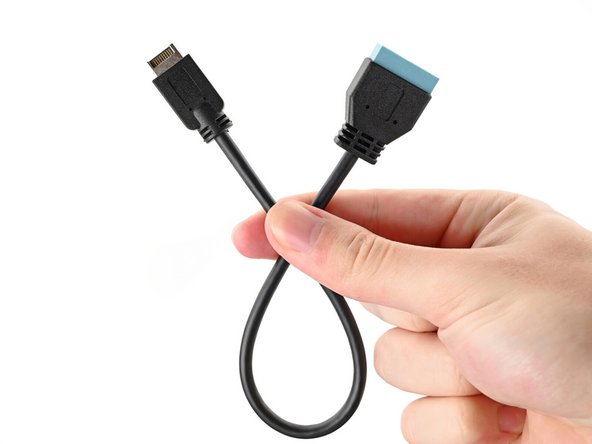
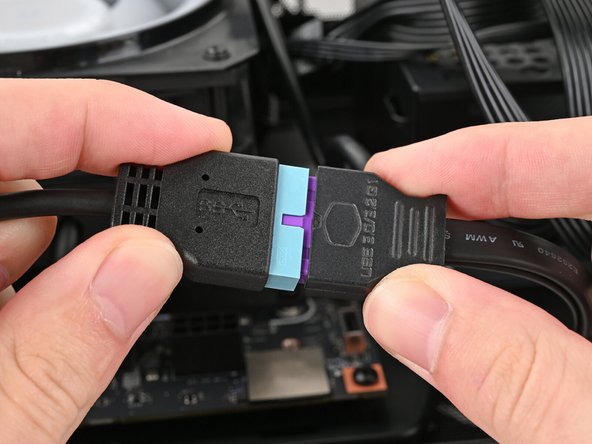
If your case comes with a USB 3.0 20-pin connector, use an adapter to connect it to the other USB Type-E 20-pin socket.
-
-
-
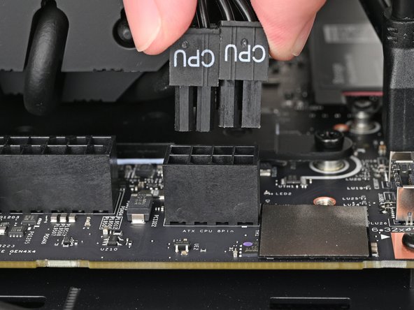
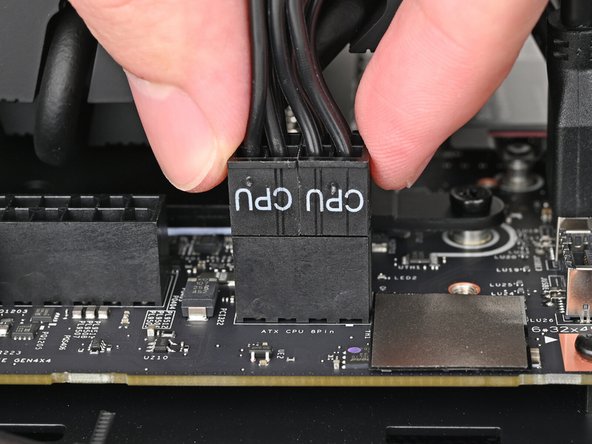
Orient the 8-pin CPU power supply cable so its clip(s) are facing the heatsink.
-
Depending on your case, your cable might be split into two heads with their own clips.
-
Slide the cable into its socket on the Mainboard until you feel its clips click into place.
-
-
-
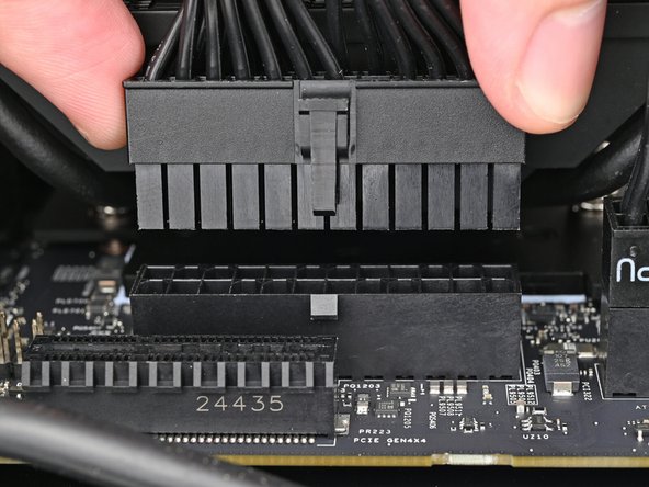
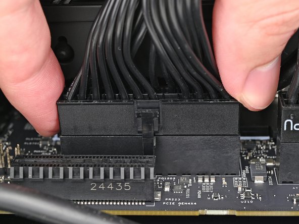
Orient the 24-pin main power supply cable so its clip is facing away from the heatsink.
-
Slide the cable into its socket on the Mainboard until you feel its clip click into place.
-
-
-
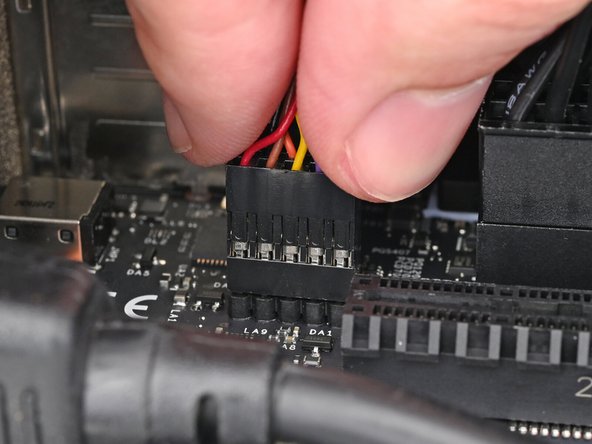
Slide the HD audio cable into its 9-pin connector next to the main power supply connector.
-
-
-
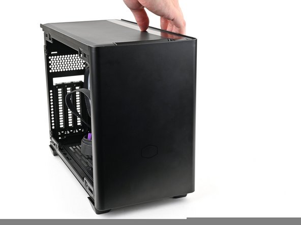
Stand your case upright.
-
-
-
Disassemble your case enough to access the bottom side of the Mainboard.
-
-
-
Lay your case down so the bottom of the Mainboard is facing upright.
-
-
-
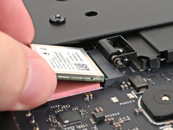
Hold the Wi-Fi module by its edges. Don't touch the gold contacts with your fingers. If you do, wipe the contacts with a clean, lint-free cloth to remove any finger oils.
-
Align the Wi-Fi module's gold contacts and notch with the socket on the Mainboard.
-
Insert the Wi-Fi module into the socket at a shallow angle. The gold contacts should mostly be covered by the socket.
-
The Wi-Fi module fits into the socket in one orientation. If it doesn't fit, try flipping the module.
-
-
-
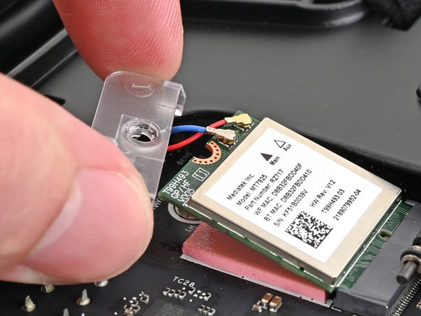
The color of your antenna cables will depend on the antenna module you're using. Refer to the instructions of your antenna module for which cables should connect to the two sockets on the Wi-Fi module.
-
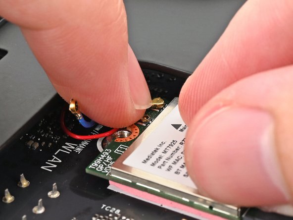
Hold the Wi-Fi module down with your fingers.
-
Position the antenna cable connector over the left Wi-Fi module's coaxial socket.
-
Tweezers can help position the connector.
-
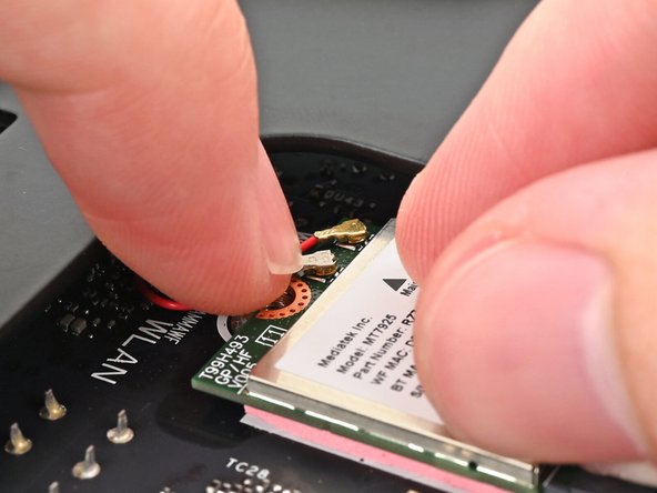
Use your finger to press the connector into place. You should feel a faint click, and the cable will stay attached to the socket by itself.
-
These connectors are very delicate! If the connector doesn't feel like it's clicking in place, reposition the connector and try again.
-
Repeat the procedure with the other antenna cable.
-
-
-
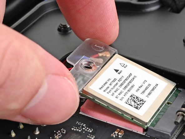
Hook the Wi-Fi bracket over the corner of the Wi-Fi module opposite the antenna cables.
-
Rotate the bracket over the Wi-Fi module, making sure the screw hole isn't being obstructed by the antenna cables.
-
-
-
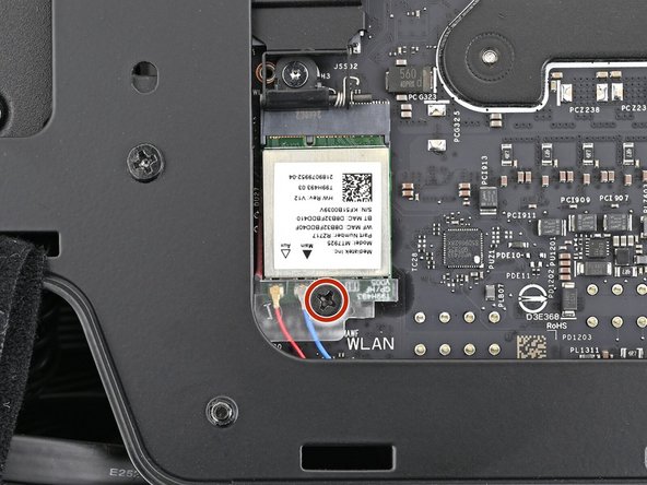
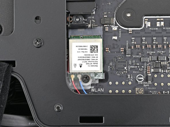
Use your Framework Desktop Screwdriver to install the 7.0 mm‑long screw securing the Wi-Fi module.
-
-
-
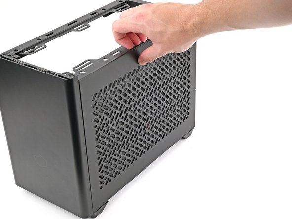
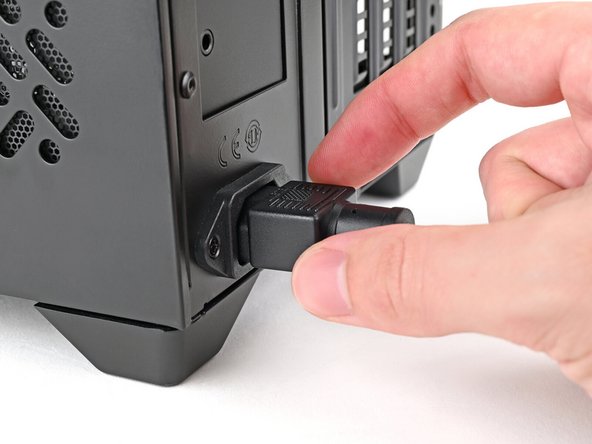
Reassemble the case and plug the AC Cable into the desktop.
-
-
-
You're done installing your Framework Desktop Mainboard! If you haven't transferred your data, you'll need to install an OS.
-
If you're installing Microsoft Windows, check out this guide.
-
If you're installing Linux, check this page for more details.
-


For drivers, firmware, and software updates, check out this page.
If you need help, contact Framework support.
For drivers, firmware, and software updates, check out this page.
If you need help, contact Framework support.