Introduction
Congratulations on getting your capable hands on a Framework Laptop 13 Pro DIY Edition! Follow this quick start guide to assemble your Laptop and get it running.
- If you got the Pre-Built Framework Laptop 13 Pro, follow this Quick Start guide instead.
After assembling your Laptop, you'll need to install an OS and download the correct drivers. Here are links to some useful resources:
Tools

Parts
No parts specified.
-
-
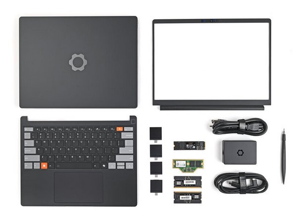
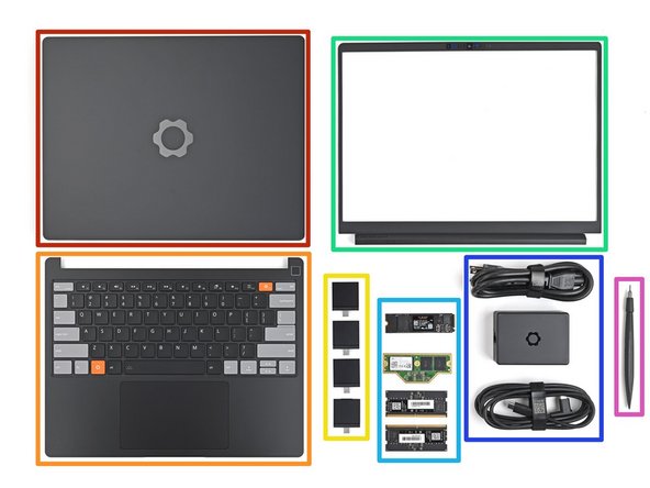
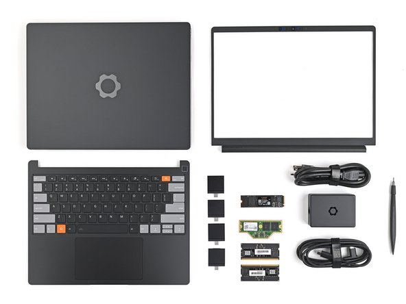
Unbox your Framework Laptop and make sure you've received the following items (the exact contents will vary depending on your configuration):
-
Framework Laptop Chassis with pre-installed Mainboard.
-
Input Cover
-
Expansion Cards
-
Bezel
-
Storage (SSD) and Memory (LPCAMM2 or DDR5 SO-DIMM depending on your configuration)
-
Power Adapter
-
Framework Screwdriver
-
-
-
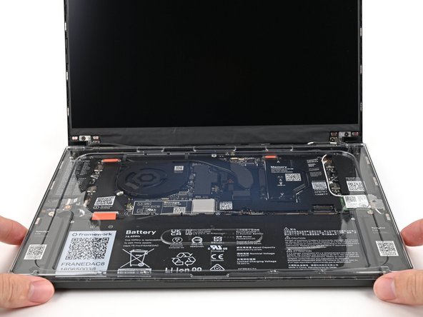
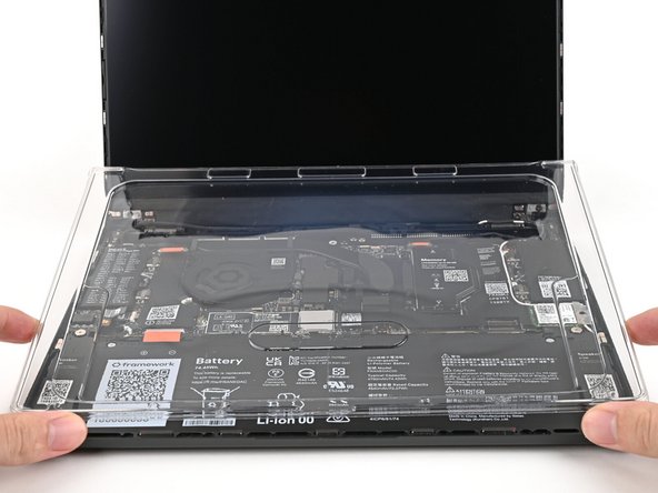
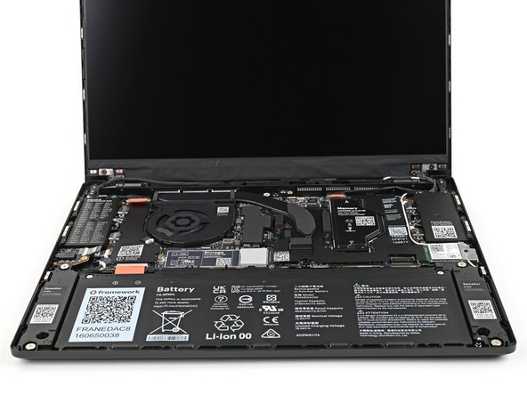
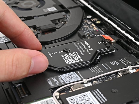
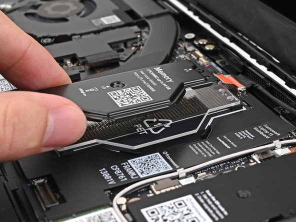
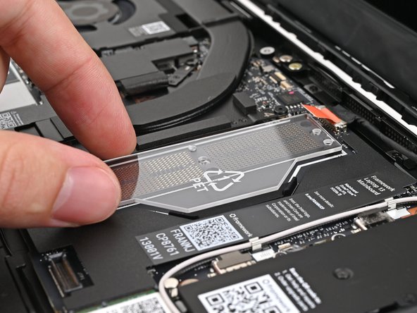
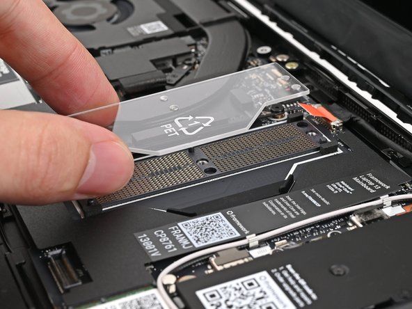
Open the Laptop and remove the plastic cover.
-
The protective cover is made of post-consumer recycled PET and is highly recyclable. Please recycle this with your household recycling.
-
-
-
If you're installing a LPCAMM2 module, follow the next six steps. If you're installing DDR5 SO-DIMM modules, skip here.
-
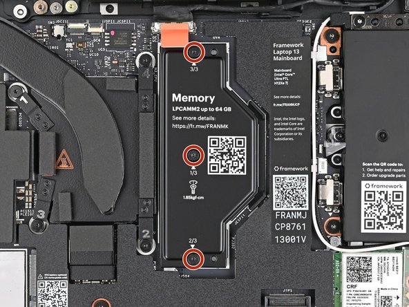
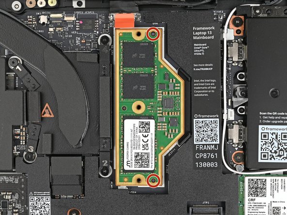
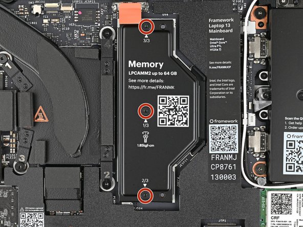
Use your Framework Screwdriver to loosen the captive T5 Torx screws securing the LPCAMM2 Memory Cover in reverse order from 3–1.
-
-
-
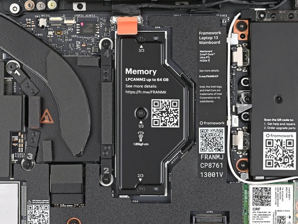
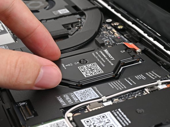
Lift the LPCAMM2 Memory Cover straight off the memory and remove it.
-
-
-
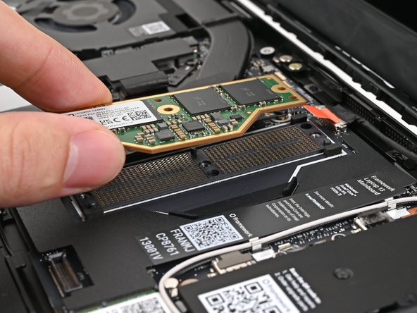
Remove the LPCAMM2 Memory Spacer and recycle it.
-
Avoid touching the Interposer below the Spacer. If the Interposer accidentally shifts, grab it by its edges to place it back into its alignment pegs.
-
Make sure there's no dust or debris on top of the Interposer before continuing.
-
-
-
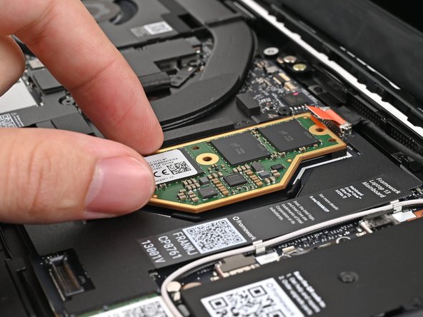
Place the LPCAMM2 module on top of the Interposer, making sure it slots into its alignment pegs.
-
-
-
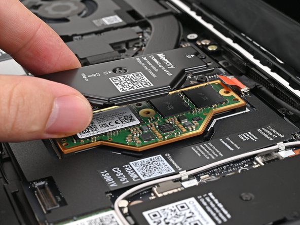
Place the LPCAMM2 Memory Cover on top of the memory, making sure its screws align with the screw holes.
-
The cover should lay flat when aligned properly.
-
-
-
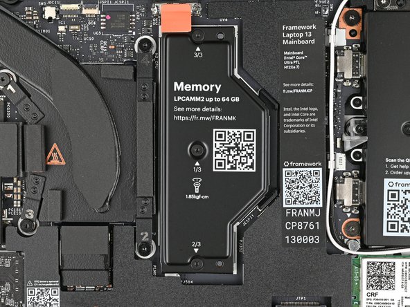
Use your Framework Screwdriver to tighten the captive T5 Torx screws securing the LPCAMM2 Memory Cover in order from 1–3.
-
Make sure the screws are snug enough to create proper contact between the memory and the Mainboard.
-
Skip to this step.
-
-
-
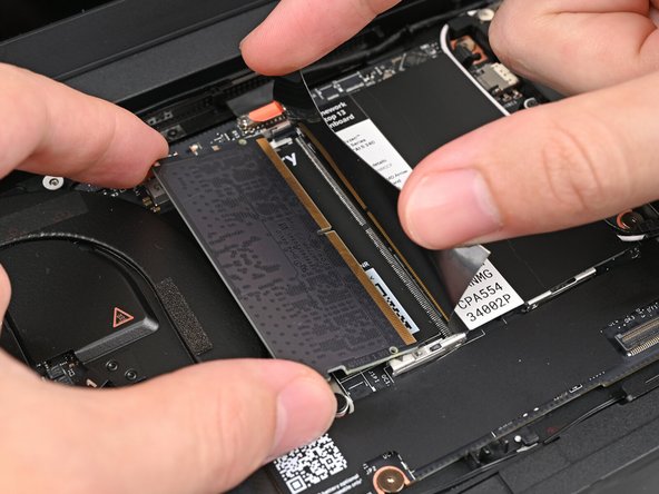
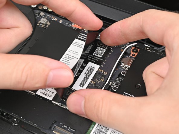
Hold the memory module by its edges. Don't touch the gold contacts with your fingers. If you do, wipe the contacts with a clean, lint-free cloth to remove any finger oils.
-
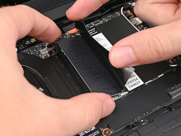
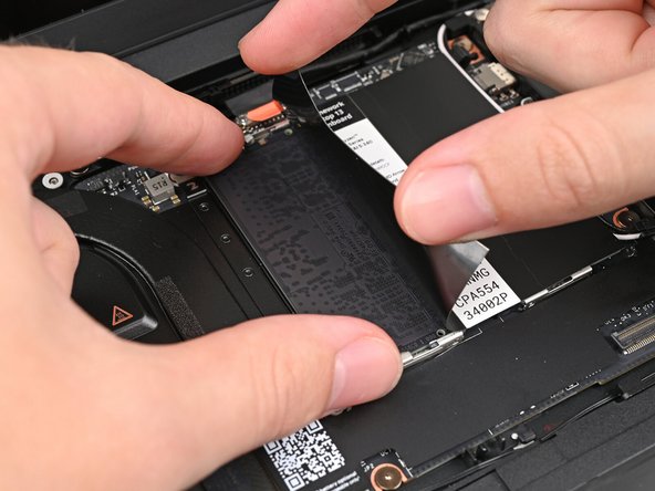
While holding up the black flap covering the left memory module labeled ("Channel 0"), orient the module with its label facing down and align the gold contacts with the socket.
-
Insert the contact edge into the socket at a shallow angle. The gold contacts should mostly be covered by the socket.
-
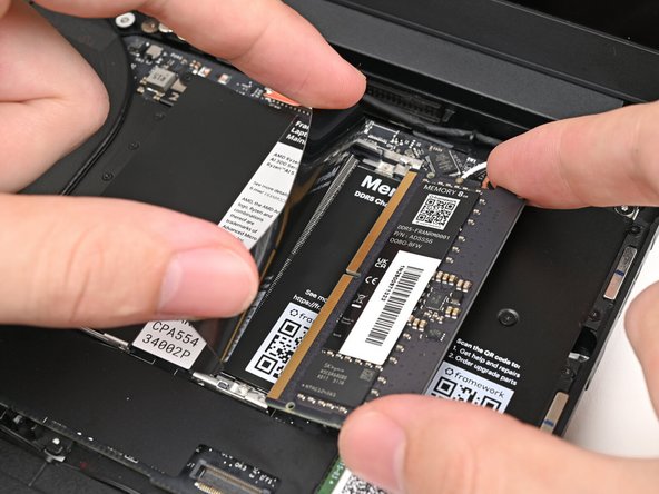
Press the edges of the memory module down until the side clips lock it in place.
-
-
-
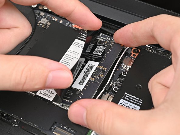
Repeat the previous step for the right socket labeled ("Channel 1"), except orient the module so its label is facing up.
-
-
-
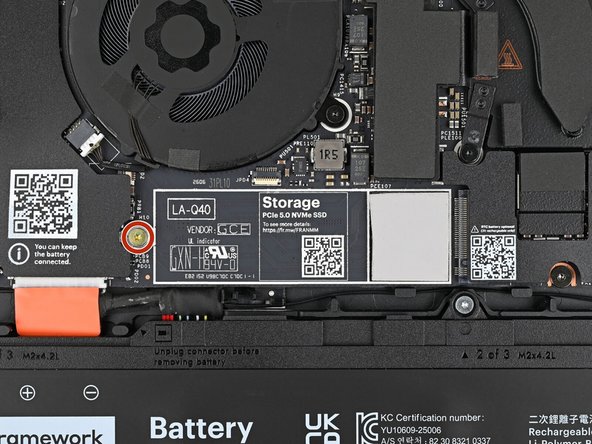
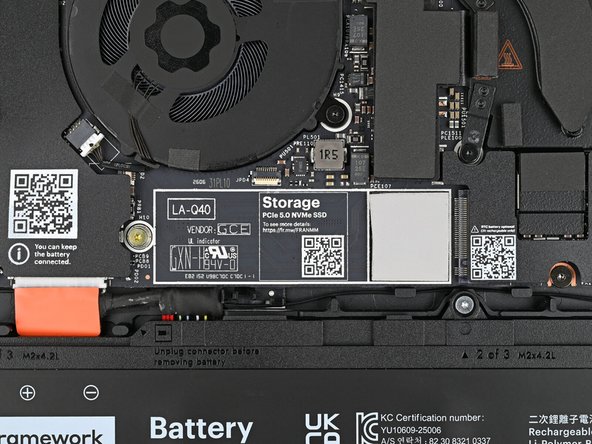
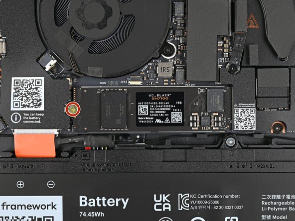
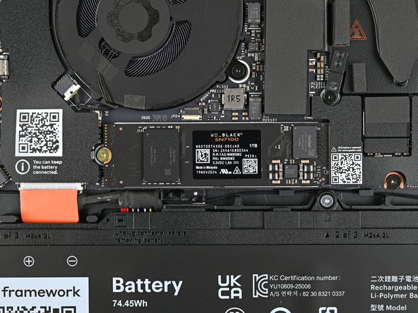
Use your Framework Screwdriver to remove the 3.0 mm‑long T5 Torx screw near the SSD connector.
-
Do NOT remove the film on the Thermal Pad. It is a special material to maintain both the thermal effect and retain the shape.
-
-
-
If you’re installing a double-sided SSD, you’ll first need to remove the thermal pad on the Mainboard. If your SSD has a heat-spreader, you’ll also need to remove that or avoid installing it. See this notice for more information.
-
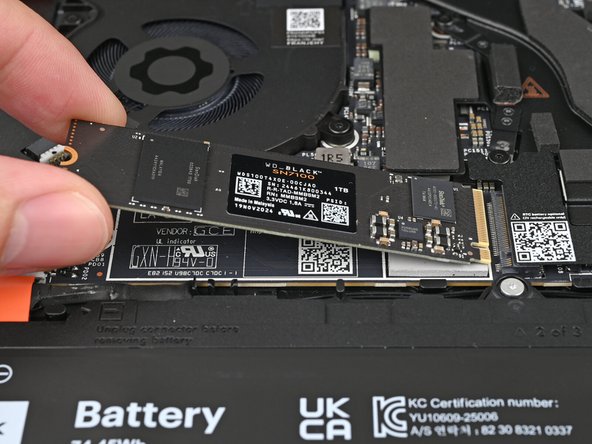
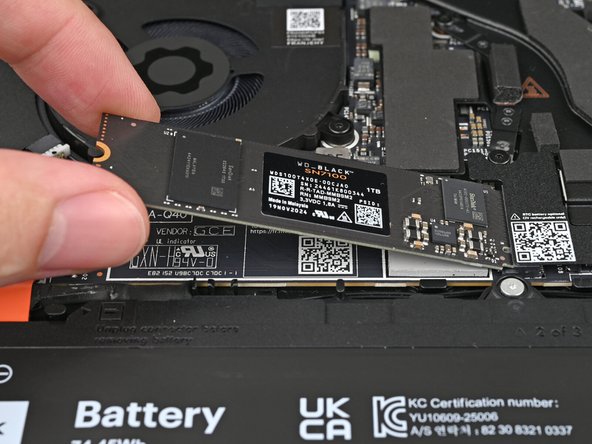
Hold the SSD by its edges. Don't touch the gold contacts with your fingers. If you do, wipe the contacts with a clean, lint-free cloth to remove any finger oils.
-
Insert the SSD into the socket at a shallow angle. The gold contacts should mostly be covered by the socket.
-
The SSD fits into the socket in one orientation. If it doesn't feel like it fits, try flipping the module.
-
-
-
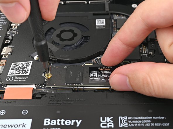
While holding the SSD flat to the Mainboard, use your Framework Screwdriver to install the 3.0 mm‑long T5 Torx screw securing the SSD.
-
-
-
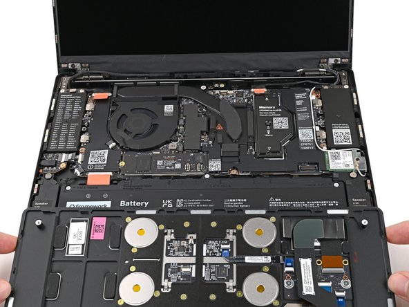
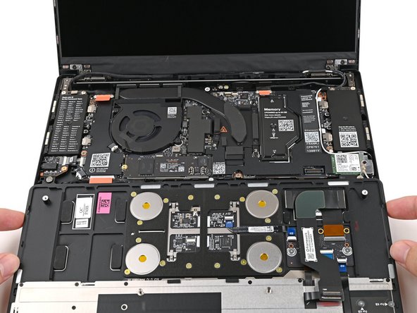
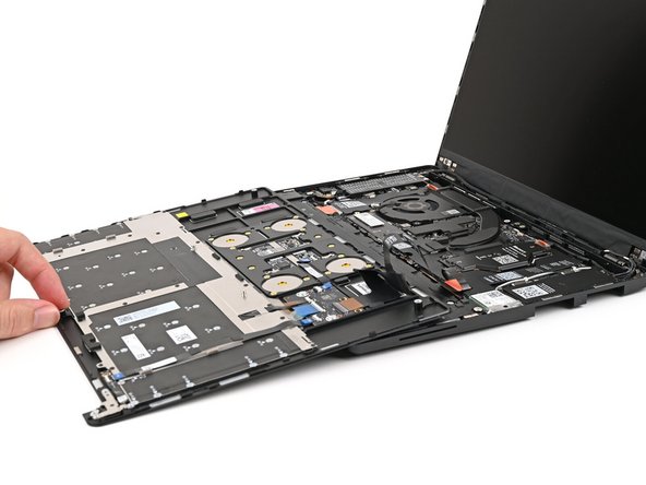
Position the Input Cover, Keyboard down, on top of the Laptop so it just covers the Battery.
-
This allows the Touchpad Cable to be folded over and reconnected without straining it.
-
-
-
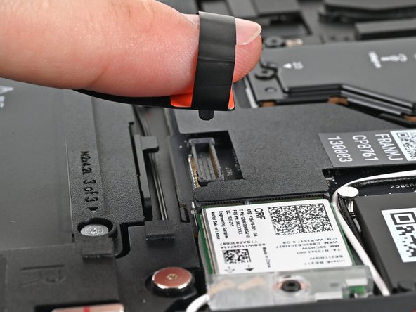
Insert your finger into the Touchpad Cable press connector loop.
-
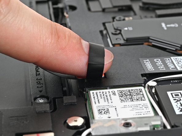
Align the press connector over its socket and press down with your finger.
-
You should hear it "click" into place. If you're having trouble, reposition it and try again. Don't try to force the connector into place.
-
-
-
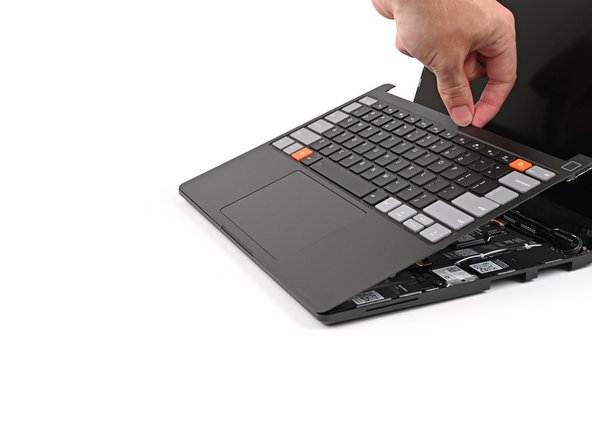
Flip the Input Cover over the Laptop and align the bottom edges.
-
-
-
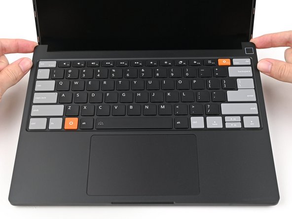
Lay the Input Cover over the Laptop and let the magnets snap it into place.
-
The bottom right corner of the Input Cover won't sit flush with the Laptop until you tighten its screws.
-
-
-
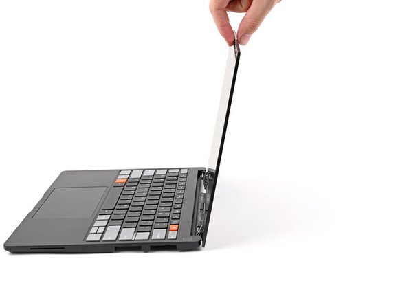
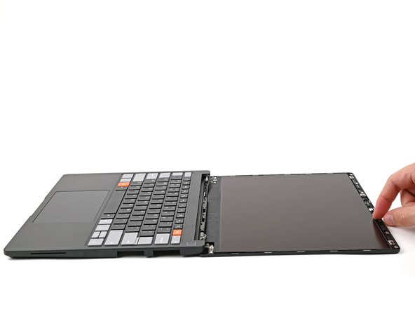
Open the Laptop so the screen sits flat on your work surface.
-
-
-
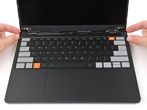
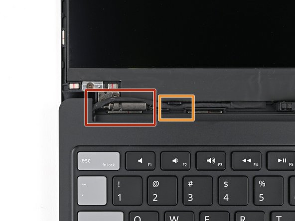
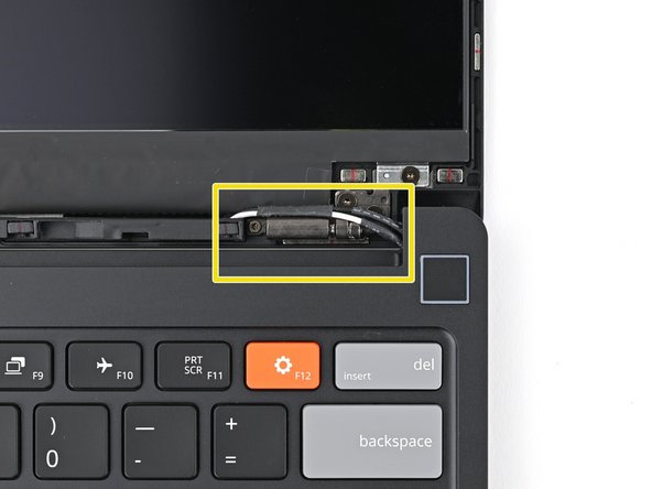
Before continuing, check if the cables next to the hinges are routed properly:
-
The Display Cable should be routed just above the hinge without any large gaps.
-
The Display Cable should be routed between the metal clips.
-
The Webcam Cable should be routed just above the hinge without any large gaps and shouldn't overlap with the Antenna Cables.
-
If the cables aren't routed properly, the Bezel won't sit flat and you risk damaging the Bezel and the Display during reassembly.
-
-
-
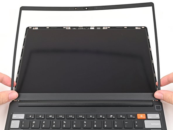
If there's any liners covering adhesive on the back of the Bezel, remove them now.
-
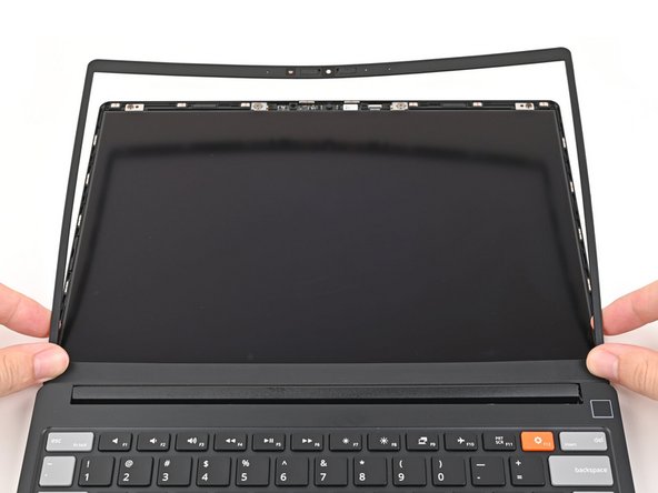
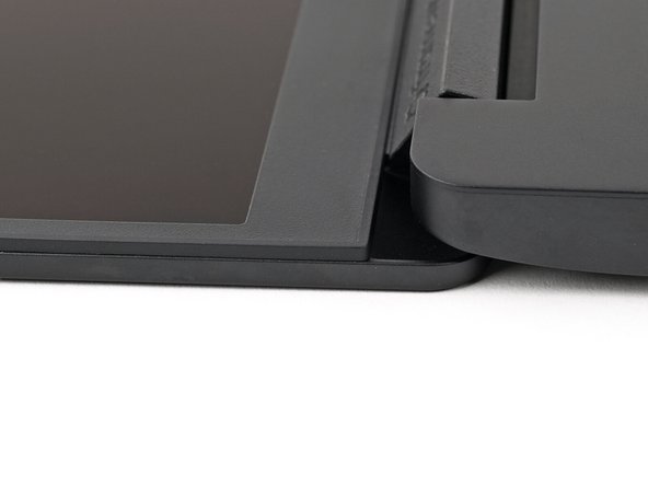
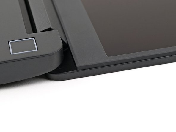
Align the bottom edge of the Bezel with the top edge of the Input Cover and press down so the Bezel covers the hinges and cables.
-
The bottom edge of the Bezel should sit flat and the magnets at its edges should "snap" into place.
-
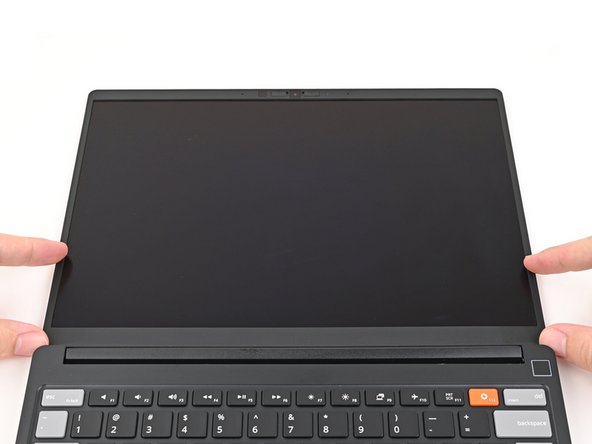
Lay the rest of the Bezel over the screen and let the magnets pull it into place.
-
-
-
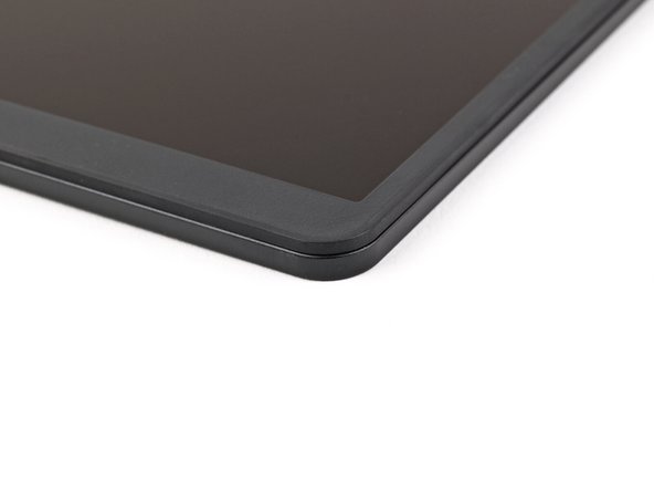
Check that all four corners of the Bezel sit flat on the screen. If they're uneven, do the following:
-
Use your fingers to press around the edge of the Bezel. The magnets should easily snap into place.
-
If the Bezel is still uneven, remove the Bezel and reseat it. Refer to this step for how the cables should be routed.
-
-
-
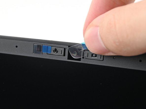
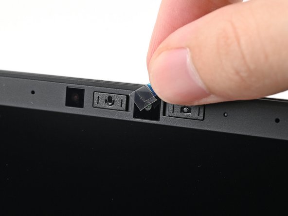
If there are any plastic liners covering the webcam and microphone, remove them.
-
-
-
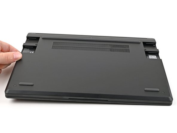
Close the Laptop and flip it over.
-
-
-
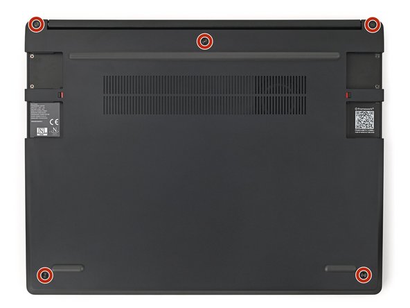
Use your Framework Screwdriver to tighten the five captive T5 Torx screws securing the Input Cover.
-
Don't overtighten the screws—just make sure they're snug.
-
-
-
For Expansion Card compatibility, check here.
-
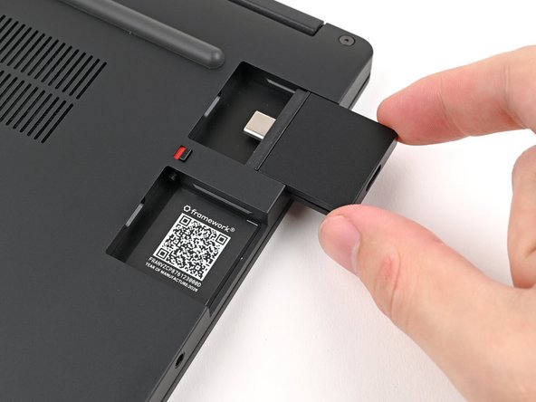
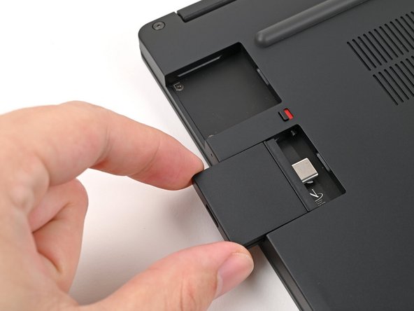
Slide an Expansion Card into an Expansion Card slot.
-
You don't need to unlock the latch to install the Expansion Cards—only when you want to remove them.
-
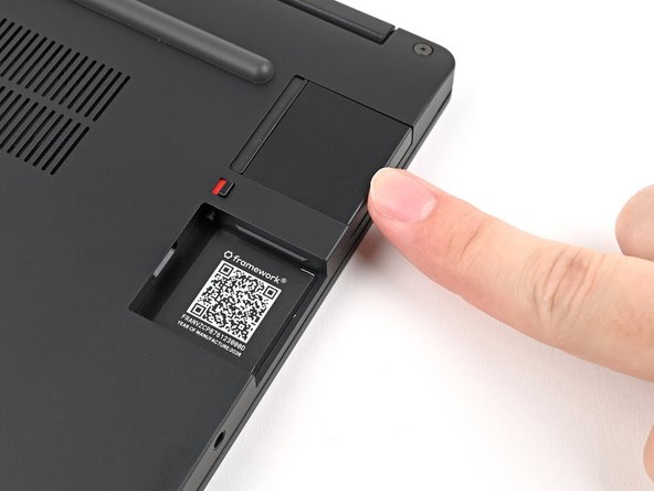
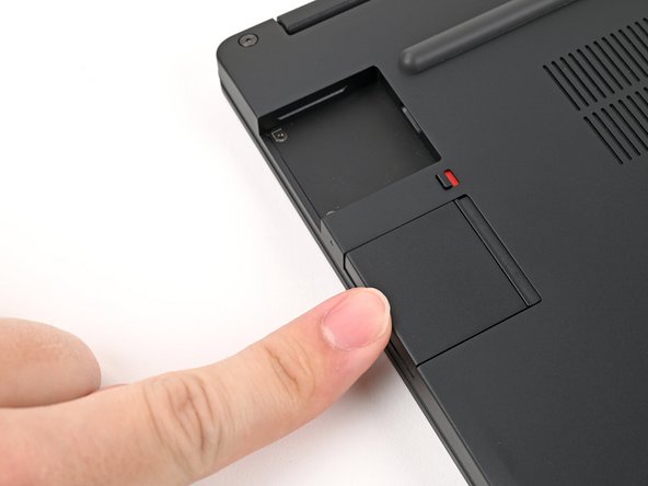
The Expansion Cards should click into place, and the front edge should be flush with the Laptop.
-
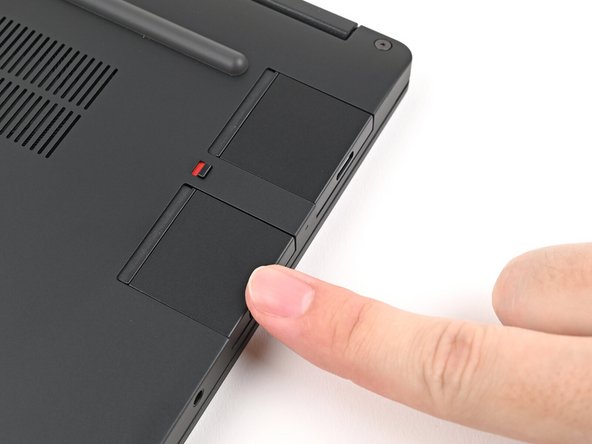
Repeat for the remaining Expansion Cards along that edge.
-
-
-
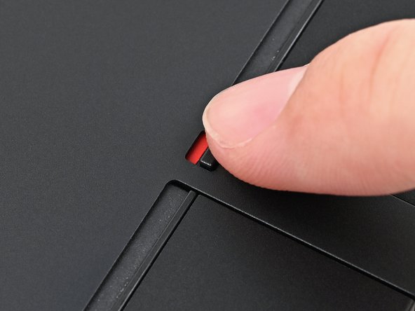
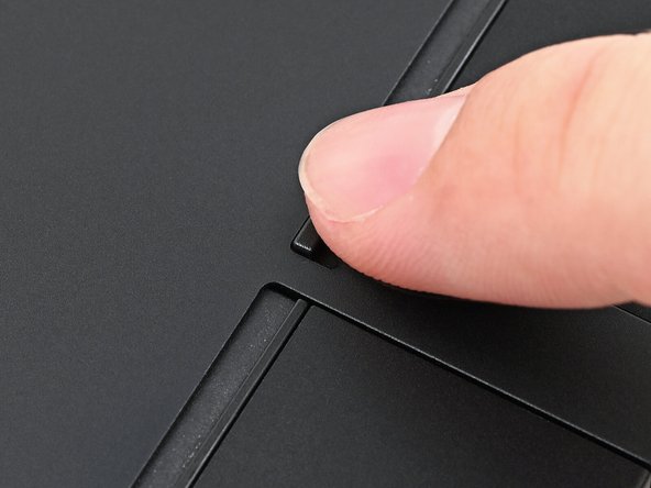
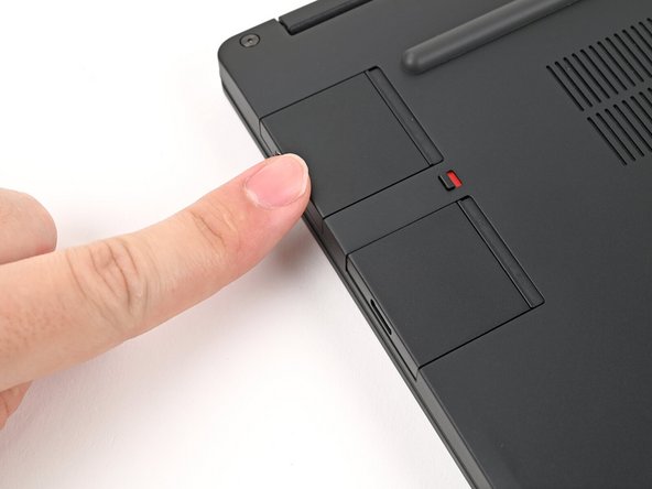
If there's a red bar showing under the Expansion Card latch, use your finger to flip the latch and lock the row of Expansion Cards above it.
-
Locking an Expansion Card helps keep it in place when you unplug cables from it.
-
-
-
Repeat the previous two steps for the other row of Expansion Cards.
-
-
-
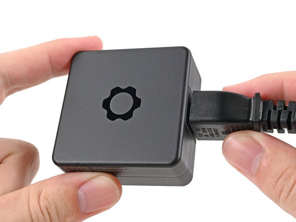
Plug the AC Cable into the Power Adapter.
-
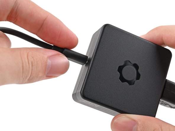
Plug the USB-C Cable into the Power Adapter.
-
You can plug either end of the USB-C cable into the adapter.
-
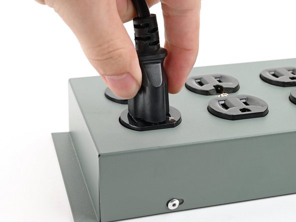
Plug the AC Cable into a power outlet.
-
-
-
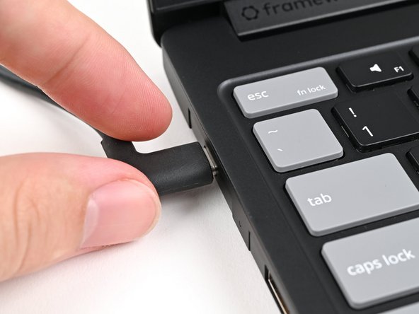
Your Framework Laptop ships in shipping mode, where the Battery is disabled until you plug the Laptop in for the first time.
-
Plug the USB-C Cable into any USB-C port on your Laptop.
-
-
-
You're done assembling your Framework Laptop! Now, you'll need to install an OS.
-
The first boot will take longer and start with a “Memory Training in Progress” screen.
-
If you're installing Microsoft Windows, check out this guide.
-
If you're installing Linux, check this page for more details.
-
For drivers, firmware, and software updates, check out this page.
-
For drivers, firmware, and software updates, check out this page.
If you need help, contact Framework support.
For drivers, firmware, and software updates, check out this page.
If you need help, contact Framework support.
Cancel: I did not complete this guide.
4 other people completed this guide.

