
Introduction
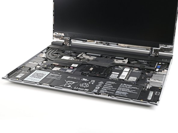
Use this guide to remove and replace the fingerprint reader in your Framework Laptop 16.
-
-
Unplug all cables and fully shut down your laptop.
-
-
-
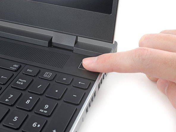
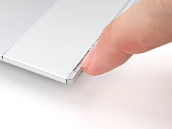
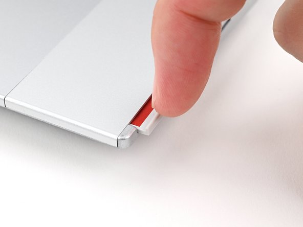
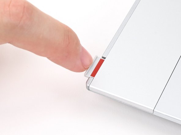
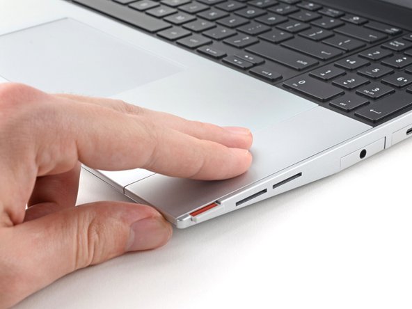
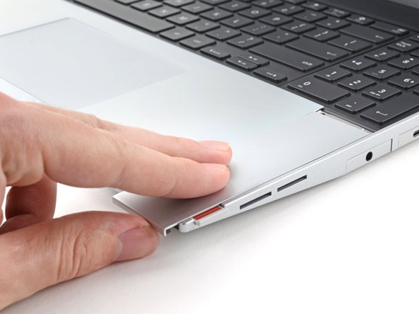
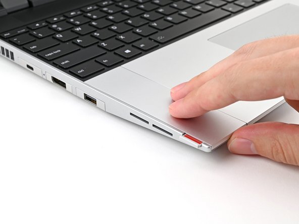
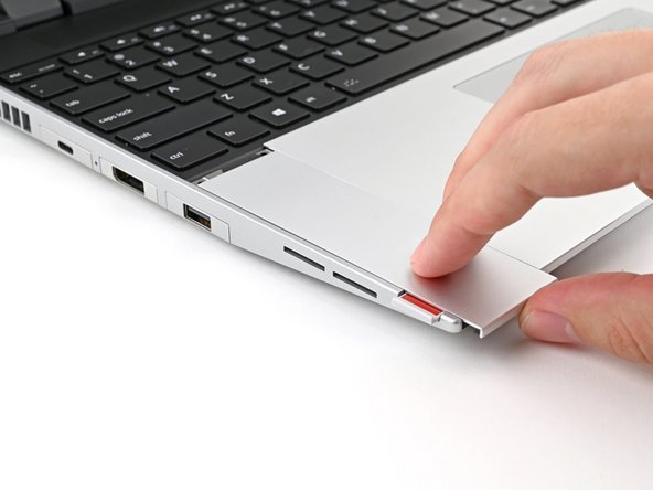
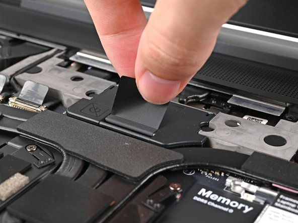
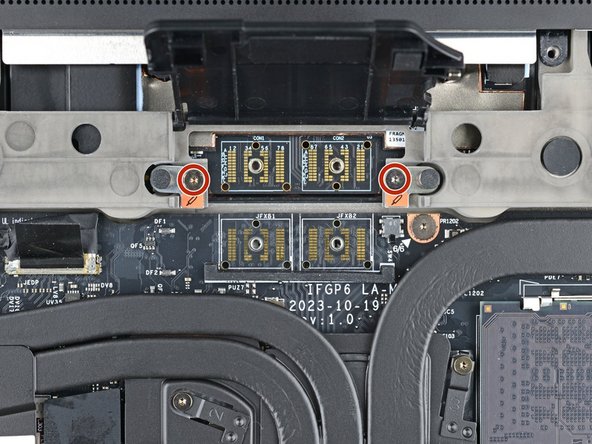
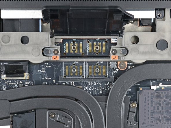
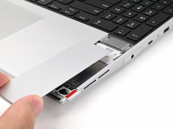
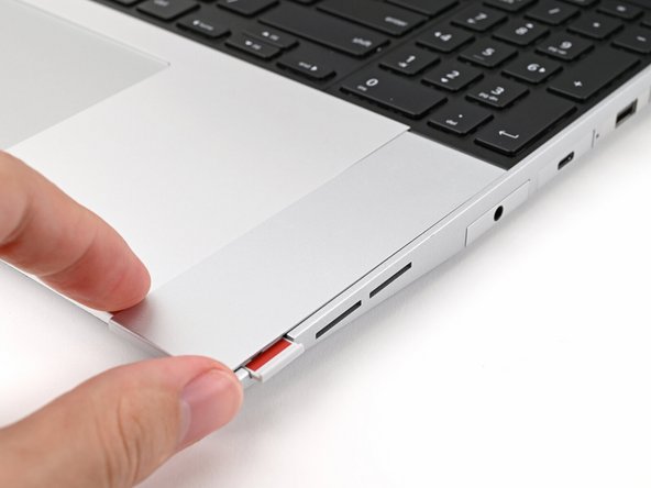
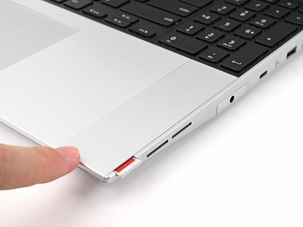
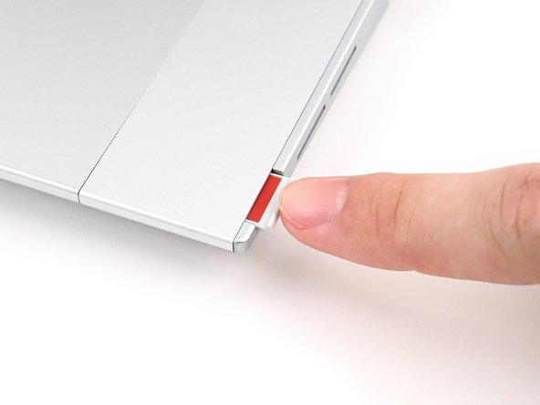
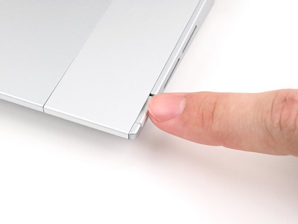
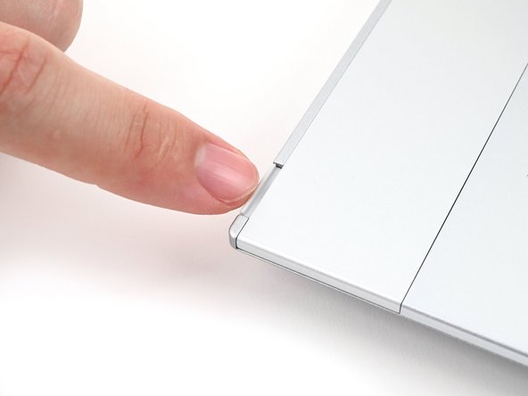
Use your fingernail to pull out the two Input Module latches and unlock them.
-
The latch will show red if it's unlocked.
-
-
-
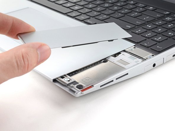
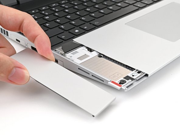
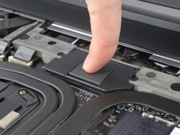
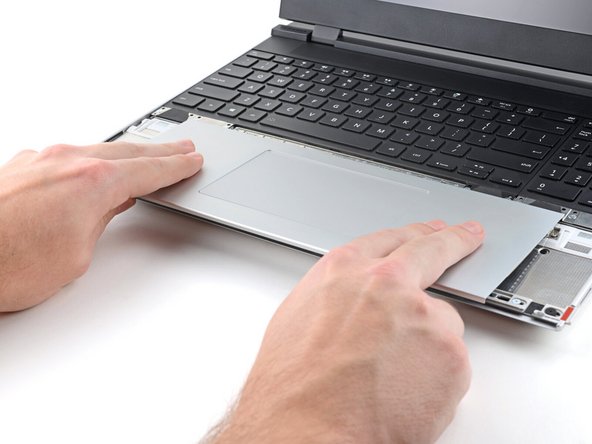
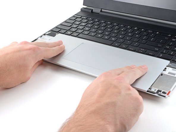
Use your fingers to slide the Touchpad Spacer toward the bottom edge of the laptop and unclip it.
-
If you're having trouble, check if the corresponding Input Module latch is properly unlocked.
-
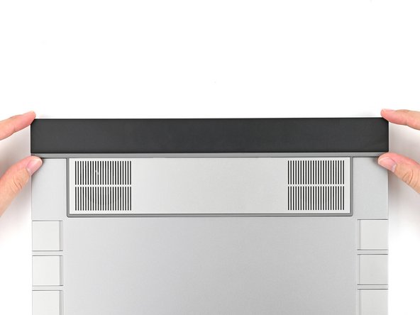
Lift the Touchpad Spacer off the laptop and remove it.
-
-
-
Repeat the same procedure for the other touchpad spacer.
-
-
-
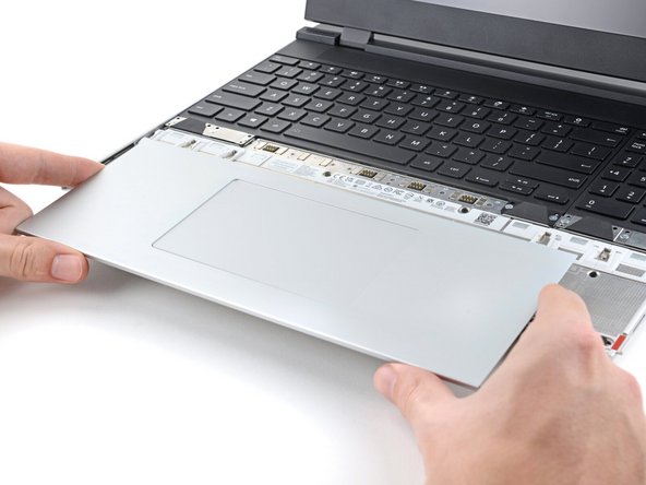
Use your fingers to slide the Touchpad Module toward the bottom edge of the laptop and disconnect it.
-
If you're having trouble, check if the Input Module latches are properly unlocked.
-
Lift the Touchpad Module and remove it.
-
-
-
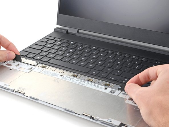
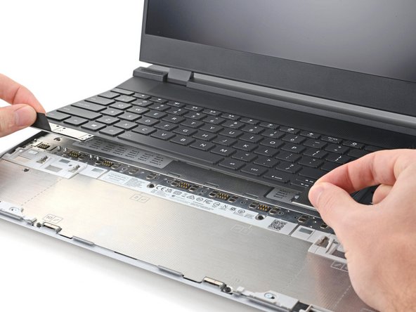
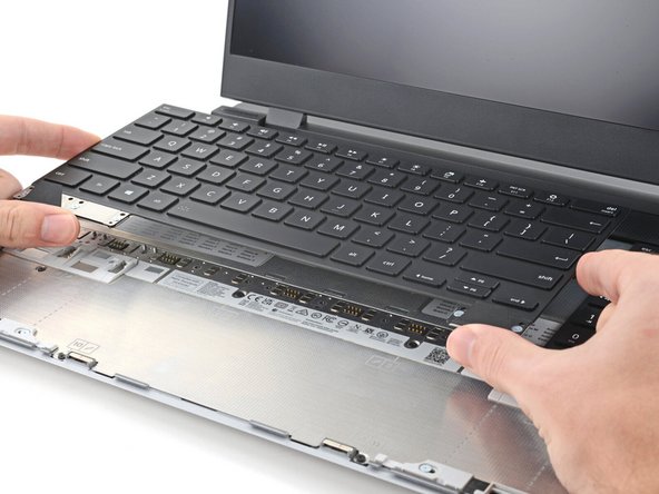
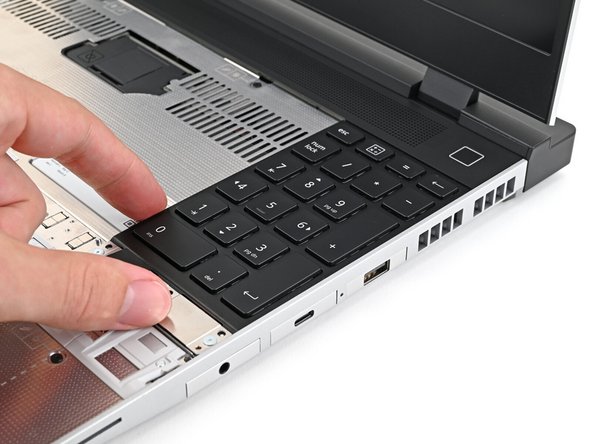
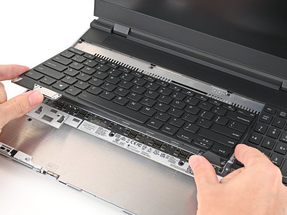
The keyboard is held in place with strong magnets. Apply gradually increasing force to avoid having the keyboard violently eject.
-
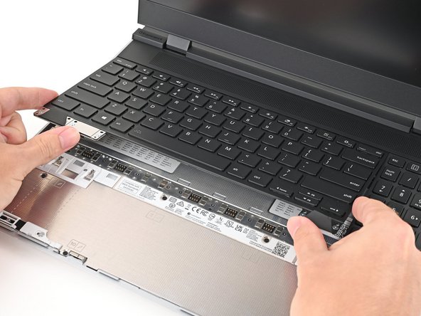
Grip the two pull tabs along the bottom of the keyboard and lift until its magnets release.
-
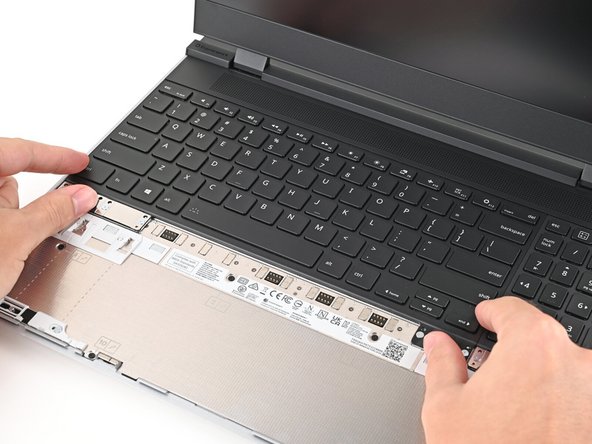
Remove the keyboard.
-
-
-
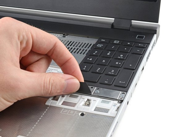
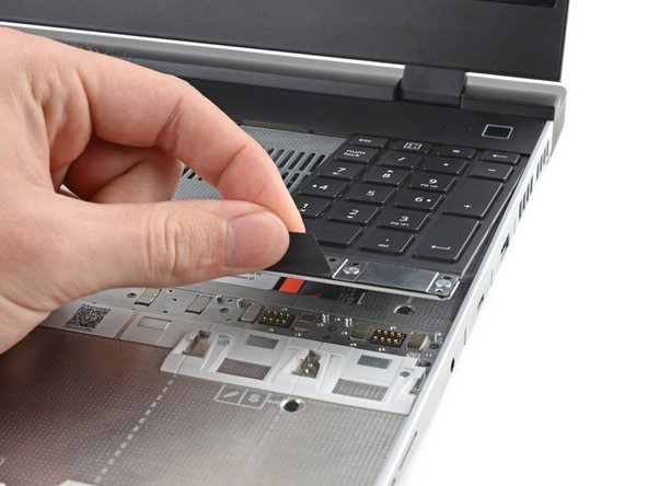
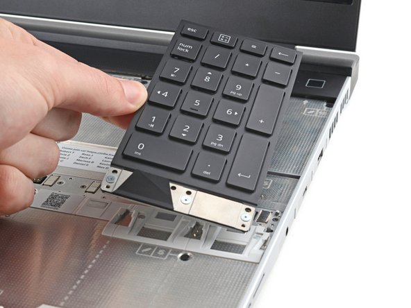
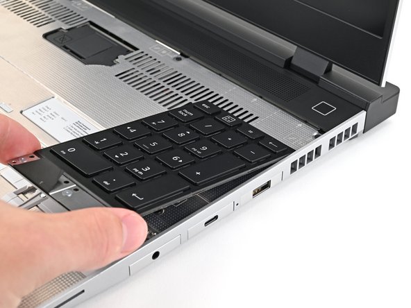
Your Input Module(s) might be different, but the procedure to remove them is the same.
-
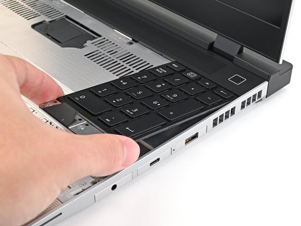
Grip the pull tab at the bottom of the Input Module and lift until its magnets release.
-
Remove the Input Module.
-
Repeat for any remaining Input Modules.
-
-
-
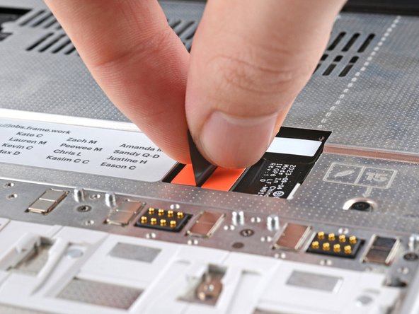
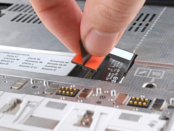
Grip the black pull tab on the Mid Plate cable press connector and lift up to disconnect it.
-
-
-
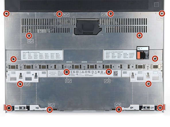
The Mid Plate screws are ordered from 2–17 (number 1 is the press connector). You don't have to follow the order, but you can use it to help keep track of the screws you've loosened.
-
Use your Framework Screwdriver to loosen the 16 captive T5 Torx screws securing the Mid Plate.
-
-
-
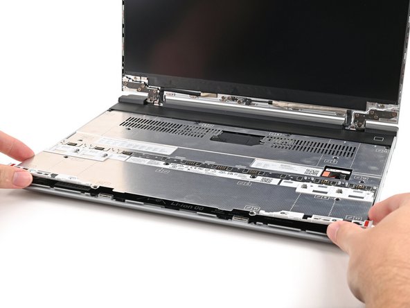
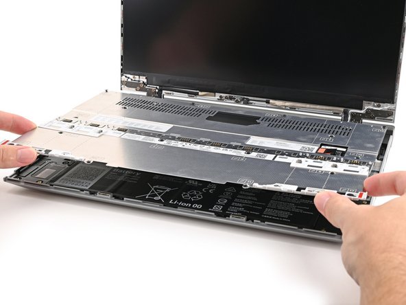
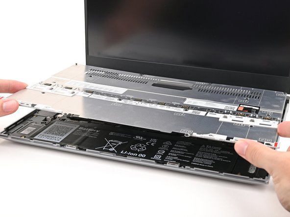
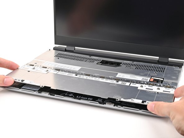
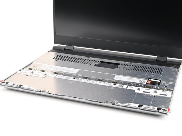
Use your fingers to lift the Mid Plate off the laptop and remove it.
-
-
-
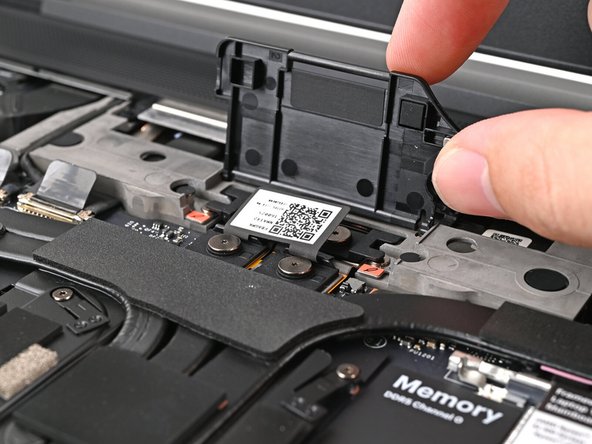
Lift the interposer door by its black pull tab and let it rest upright.
-
-
-
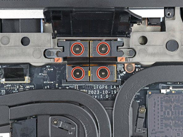
If you have the Graphics Module installed, your interposer will have four screws. If you have the Expansion Bay Shell installed, you'll have three screws instead.
-
If you have the Graphics Module, use your Framework Screwdriver to loosen the four captive T5 Torx screws securing the interposer.
-
If you have the Expansion Bay Shell, use your Framework Screwdriver to loosen the three captive T5 Torx screws securing the interposer.
-
-
-
Lift the interposer by its pull tab and remove it.
-
-
-
Use your Framework Screwdriver to loosen the two captive T5 Torx screws securing the module in the Expansion Bay.
-
Close the interposer door before continuing.
-
-
-
Close your laptop and flip it over.
-
Slide the Expansion Bay Module out of the laptop and remove it.
-
The module should slide out easily. If you feel any resistance, check if the screws holding it in place are fully loosened.
-
Reopen your laptop and flip it over.
-
-
-
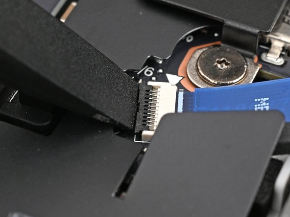
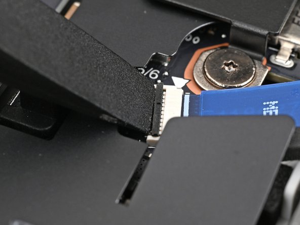
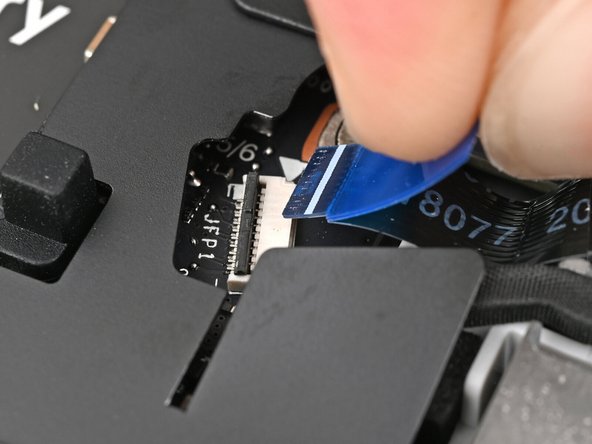
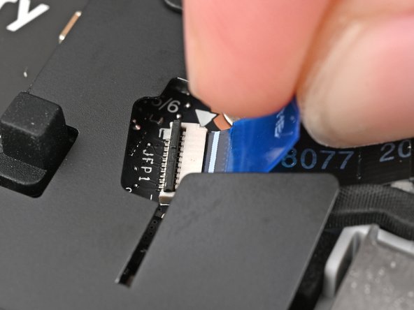
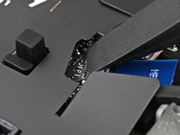
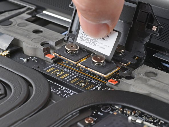
Use the flat end of a spudger, or a clean fingernail, to lift up the locking tab on the fingerprint sensor ZIF connector next to the memory.
-
-
-
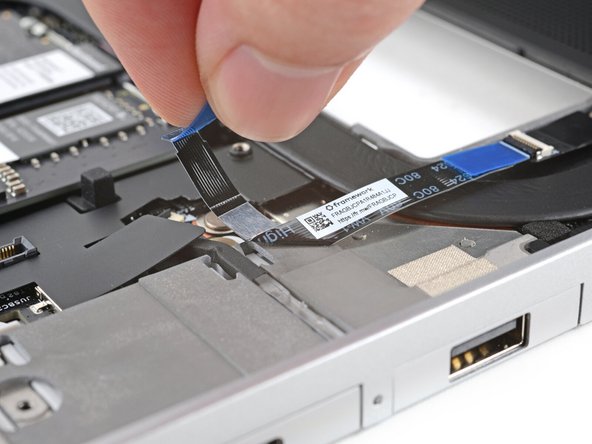
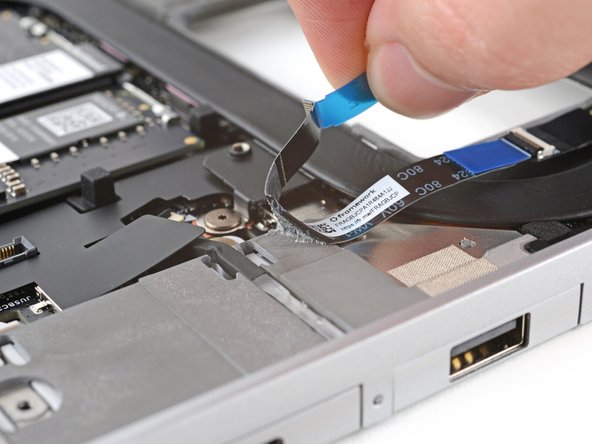
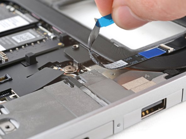
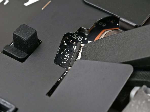
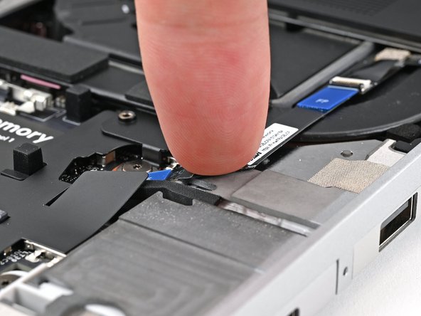
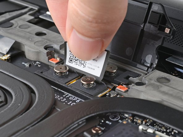
The fingerprint sensor cable is lightly adhered to the laptop's frame.
-
Use your fingers to peel the fingerprint sensor cable away from the frame and separate the adhesive.
-
-
-
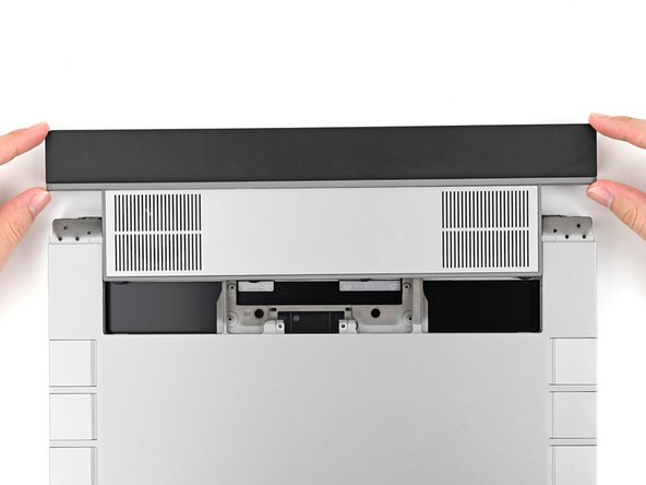
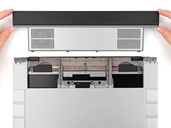
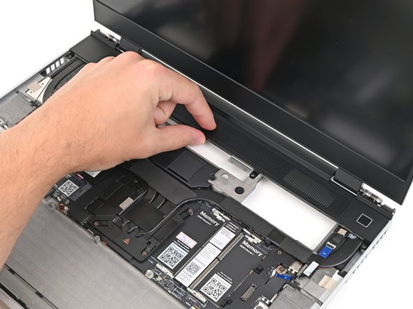
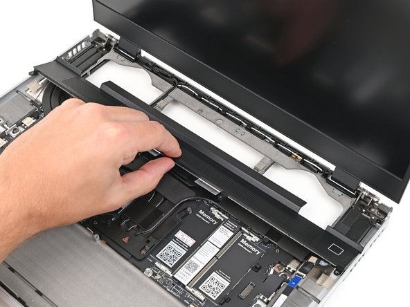
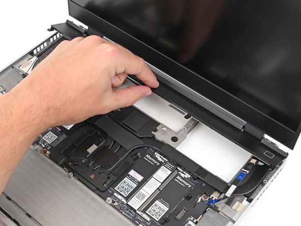
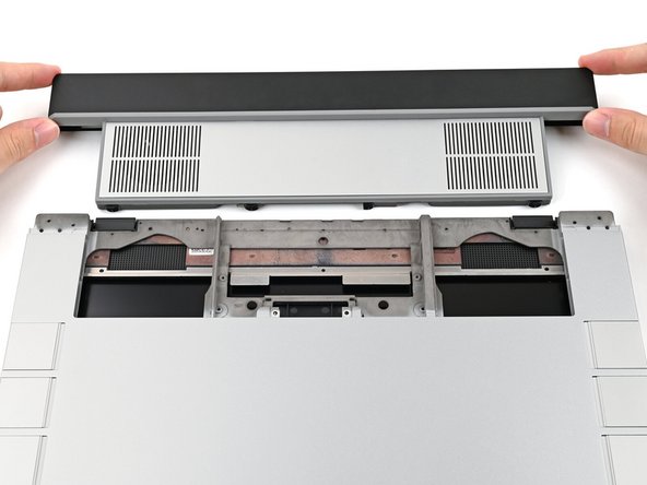
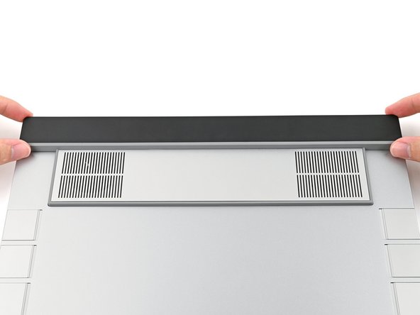
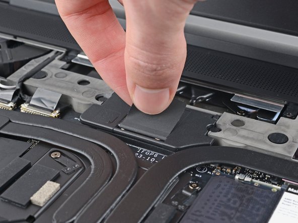
The ventilation plate is held in place with magnets.
-
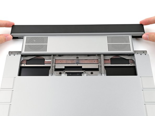
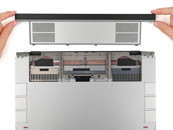
Lift the bottom of the ventilation plate and pull it away from the laptop until the magnets release.
-
Remove the ventilation plate.
-
-
-
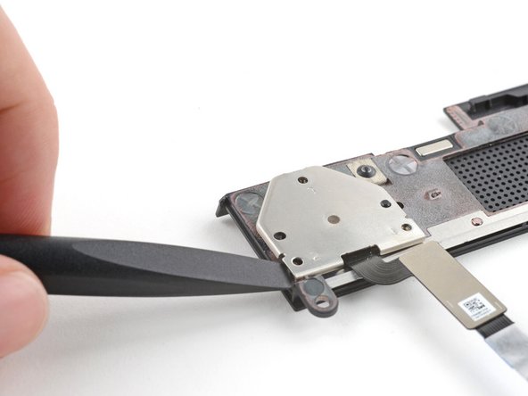
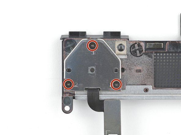
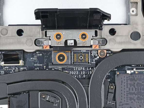
The fingerprint reader cover screws are marked 1–3. You don't need to follow this order, but you can use it to help keep track of the screws you've removed.
-
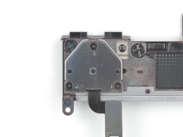
Use your Framework Screwdriver to remove the three 2.0 mm‑long Phillips screws securing the fingerprint reader cover.
-
-
-
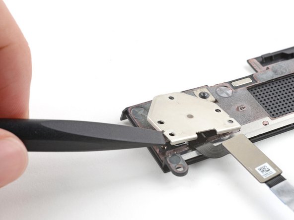
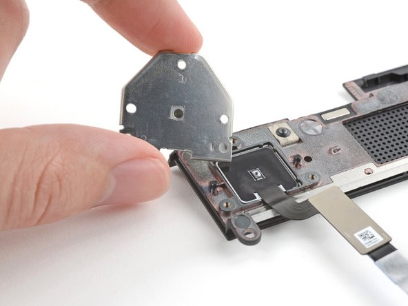
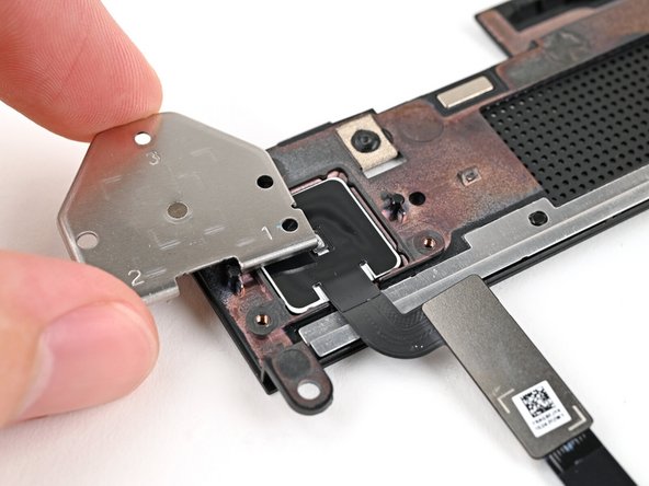
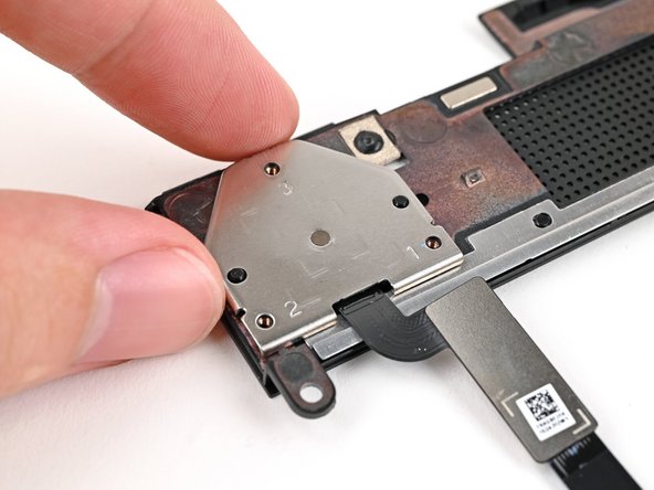
Use the flat end of your Framework Screwdriver to lift the fingerprint reader cover and remove it.
-
-
-
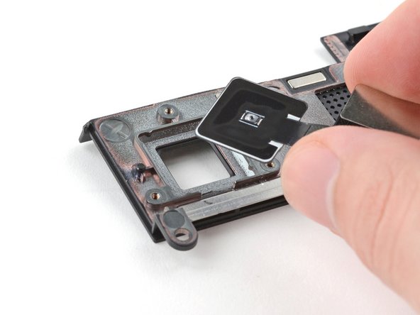
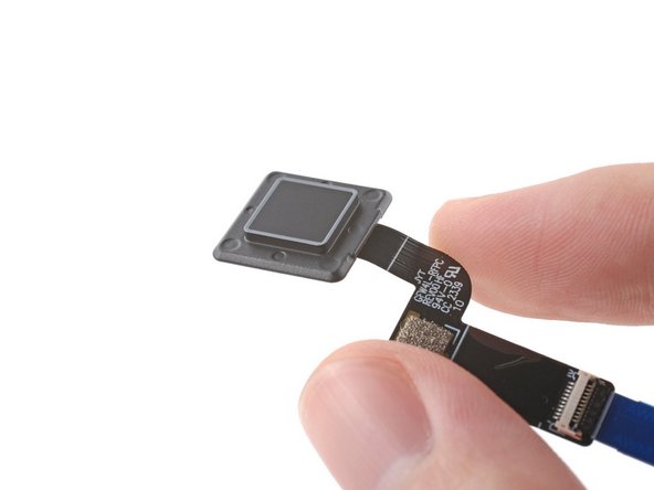
Lift the fingerprint reader out of its slot in the ventilation plate and remove it.
-
-
-
Congratulations on completing disassembly! The remaining steps will show how to reassemble your Framework Laptop.
-
-
-
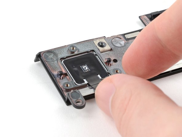
Place the fingerprint reader into its slot in the ventilation plate.
-
-
-
Place the fingerprint reader cover over the back of the reader.
-
-
-
Use your Framework Screwdriver to install the three 2.0 mm‑long Phillips screws securing the fingerprint reader cover.
-
-
-
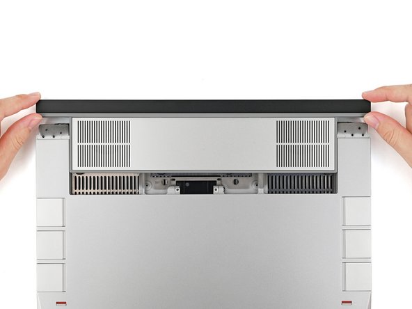
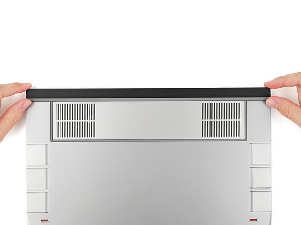
Lay the ventilation plate along the top edge of the laptop and let its magnets pull into place.
-
-
-
Use tweezers, or your fingers, to grip the blue pull tab and slide the fingerprint sensor cable straight into its socket.
-
-
-
Use the flat end of a spudger, or a clean fingernail, to press down the locking tab on the fingerprint sensor ZIF connector.
-
-
-
Press the fingerprint sensor cable to the frame to re-adhere it.
-
-
-
Align the Expansion Bay Module with its slot in the laptop.
-
Check that the module sits evenly with the rail on the outside edges of the slot.
-
Check that the two center rails are threaded between the fans.
-
-
-
While keeping the module level with the laptop, slide it into its slot.
-
The module should slide in easily. If you feel any resistance, pull the module out and realign it.
-
You should hear an audible "click" when the module's clips snap into place.
-
-
-
While keeping the shell level with the laptop, slide it into its slot.
-
The shell should slide in easily. If you feel any resistance, pull the module out and realign it.
-
You should hear an audible "click" when the shell's clips snap into place.
-
-
-
Use your Framework Screwdriver to tighten the two captive T5 Torx screws securing the Expansion Bay Module.
-
-
-
Place the interposer over its spot between the Mainboard and the module.
-
Depending on if you're installing a Graphics Module or the Expansion Bay Shell, the interposer should be oriented so either rubber grommets or metal tabs cover the Expansion Bay screws.
-
-
-
If you have the Graphics Module installed, your interposer will have four screws. If you have the Expansion Bay Shell installed, you'll have three screws instead.
-
If you have the Graphics Module, use your Framework Screwdriver to tighten the four captive T5 Torx screws securing the interposer.
-
If you have the Expansion Bay Shell, use your Framework Screwdriver to tighten the three captive T5 Torx screws securing the interposer.
-
Close the interposer door.
-
-
-
Place the Mid Plate on the laptop, making sure it sits evenly on its alignment pegs.
-
-
-
Use your Framework Screwdriver to tighten the 16 captive T5 Torx screws in order (starting with 2) to secure the Mid Plate evenly.
-
-
-
Align the Mid Plate cable press connector over its socket and press down to connect it.
-
-
-
Your Input Module(s) might be different, but the procedure to remove them is the same.
-
Align the top edge of the Input Module with the top edge of the laptop.
-
Lay the Input Module on the laptop and let the magnets pull the keyboard into place
-
Make sure the Input Module is seated properly on its alignment pegs and sits flush with the edges of the laptop.
-
Repeat for any remaining Input Modules.
-
-
-
Align the top edge of the keyboard with the top edge of the laptop.
-
Lay the keyboard on the laptop and let the magnets pull the keyboard into place
-
Make sure the keyboard is seated properly on its alignment pegs and sits flush with the edges of the laptop.
-
-
-
Place the Touchpad Module flat on its cutout so its clips are properly aligned.
-
Press the Touchpad Module down and slide it into place so it lines up evenly with the bottom edge of the laptop.
-
-
-
Place the Touchpad Spacer over its spot on the laptop with the bottom edge overhanging slightly.
-
Slide the Touchpad Spacer towards the top of the laptop to secure it.
-
Repeat the same procedure for the other Touchpad Spacer.
-
-
-
Push the Input Module latches back into place to lock them.
-


You finished fixing your Framework Laptop!
Take your e-waste to an R2 or e-Stewards certified recycler.
If you need help, contact Framework support.
You finished fixing your Framework Laptop!
Take your e-waste to an R2 or e-Stewards certified recycler.
If you need help, contact Framework support.
Cancel: I did not complete this guide.
One other person completed this guide.