
Tools
Parts
-
-
Power off the Framework Laptop by navigating to the Windows icon on the bottom left and clicking on "Power" followed by "Shut down," or if on Linux, the equivalent action there.
-
-
-
Unplug your power cable from the USB-C Expansion Card in your Framework Laptop.
-
-
-
Close the lid on your Framework Laptop and place it upside down on a soft, non-marring surface, such as the bag that it shipped in.
-
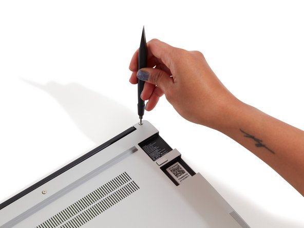
Using the T5 bit in the Framework Screwdriver, unscrew the 5 fasteners on the Bottom Cover. These fasteners will remain attached in the Bottom Cover so that you do not lose them.
-
The fastener on the bottom left (circled in red) will not unscrew as far as the others, as it is acting as a lifter for the Input Cover.
-
You'll hear this fastener start clicking as you rotate when it is unscrewed far enough.
-
Do not use a powered tool for these steps, as this will likely result in damage to the fasteners.
-
-
-
Flip the Framework Laptop back over and open the lid to around 120 degrees.
-
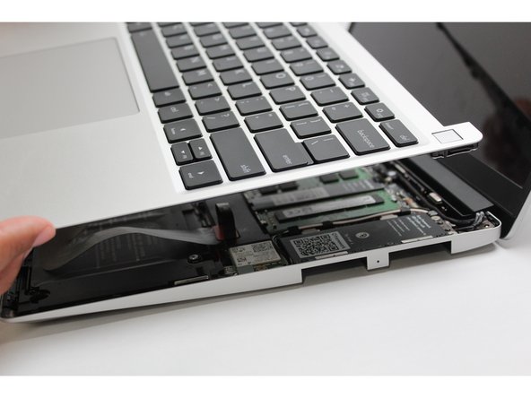
Important: Pull the Input Cover off carefully as it is still attached to the Mainboard via the Touchpad Cable. You don't need to disconnect this cable to do most repairs. You can just flip the Input Cover over. If you do want to disconnect it though, make sure to disconnect the Mainboard side using the finger loop over the orange label.
-
The bottom right corner of the Input Cover lifts up when the five fasteners are properly unscrewed from the previous step. You should not have to use any excessive force to remove the Input Cover.
-
Carefully lift the cover up from the bottom right corner. If you need to, you can use the spudger end of the Framework Screwdriver to lift it as well. Lift the Input Cover off the Mainboard, flip it over (keyboard side down), and place it about halfway on the Bottom Cover.
-
Be sure not to put too much force on the Touchpad Cable when doing this.
-
If the LEDs on the left and right sides of the system are flashing red when you lift off the cover, it means the system is still powered on. Make sure your power cable isn't plugged in and that you have shut down correctly.
-
Note that it may take up to 30 seconds after shutting down for the system to fully power off. Wait until the LEDs stop flashing before proceeding.
-
You should keep the Battery connector plugged in unless you need to replace the Battery, Mainboard, or Speakers. This connector is easy to accidentally damage, so it's better to not handle it.
-
-
-
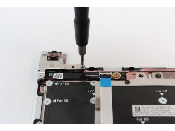
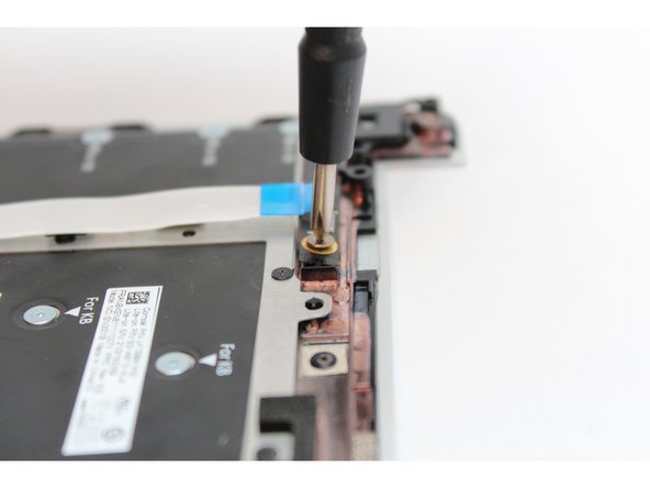
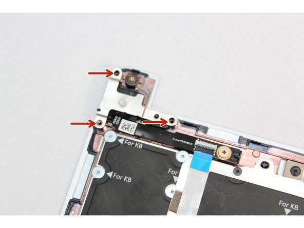
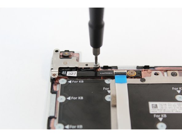
Using the T5 bit in the Framework Screwdriver, remove the three fasteners on the silver bracket holding the Fingerprint Reader in place.
-
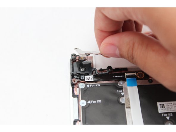
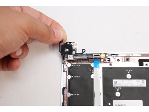
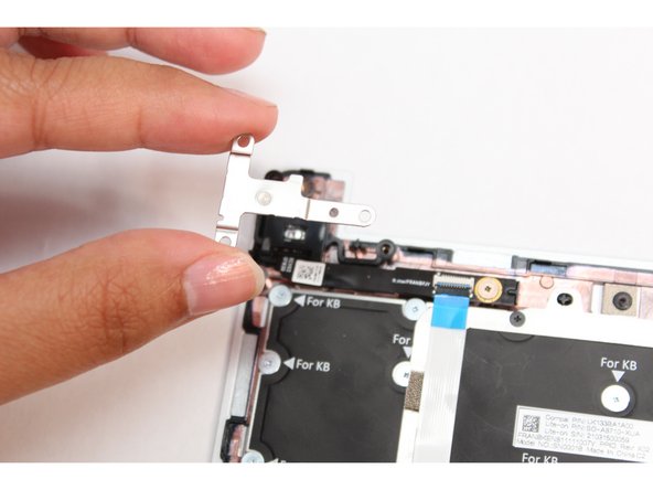
Gently lift the silver bracket off the module and move it away.
-
-
-
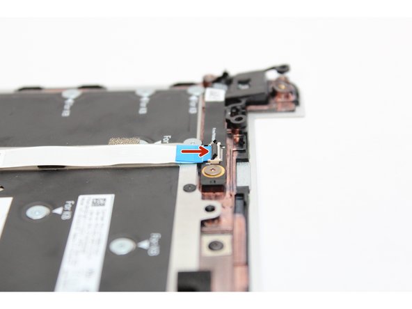
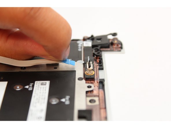
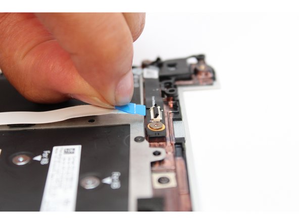
Disconnect the Fingerprint Cable from the Fingerprint Reader. Flip the black latch up using your fingernail or spudger end of the Framework Screwdriver and pull the cable straight out.
-
-
-
Using the PH0 bit in the Framework Screwdriver unscrew the fastener on the Fingerprint Module.
-
Your Framework Screwdriver has a double-sided bit! One end is the T5 bit, the other end is the PH0 bit. To switch from the T5 bit to the PH0 bit, pull the bit out using your fingers, flip it around, and place it back into the screwdriver!
-
Gently lift the Fingerprint Reader out of the Input Cover.
-
-
-
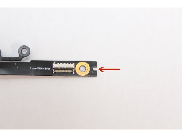
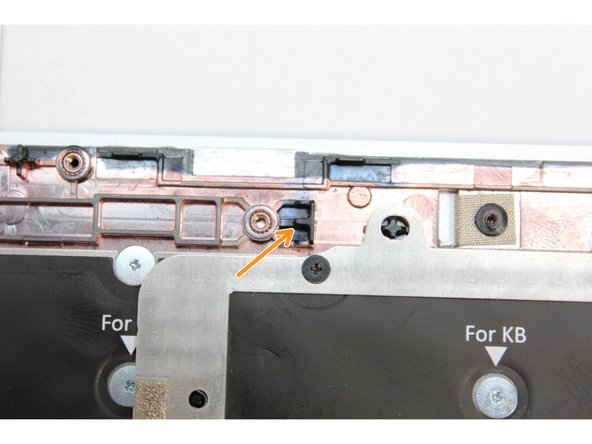
Find the notch on the end of the Fingerprint Reader Module as indicated in the first image.
-
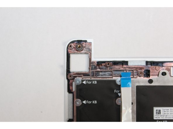
Find the alignment notch on the Bottom Cover as indicated in the second image.
-
Gently place the module on the Bottom Cover making sure to align the notch in the module with the notch on the Bottom Cover as indicated in the third image.
-
-
-
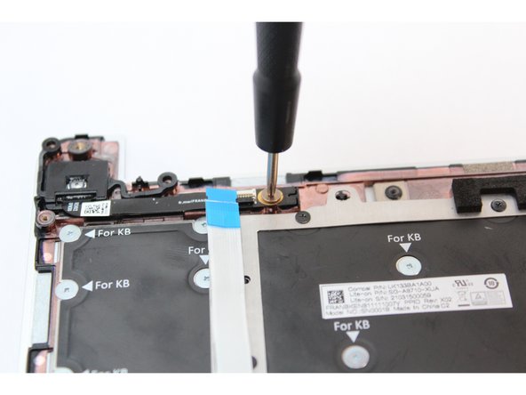
Using the PH0 bit in your Framework Screwdriver, screw the fastener into the Fingerprint Reader.
-
-
-
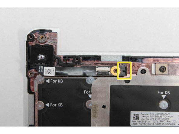
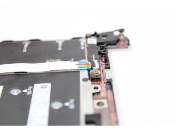
Make sure the black latch on the connector is flipped up so that you can slide the Fingerprint Cable into the connector.
-
Slide the cable straight in until the white line is almost at the edge of the connector.
-
Flip the black latch down to secure the cable.
-
-
-
Place the silver bracket over the Fingerprint Reader so that the three fastener holes align with the fastener holes on the module.
-
Using the T5 bit in the Frameworks Screwdriver screw the three fasteners into place.
-
The Fingerprint Reader is now completely installed.
-
-
-
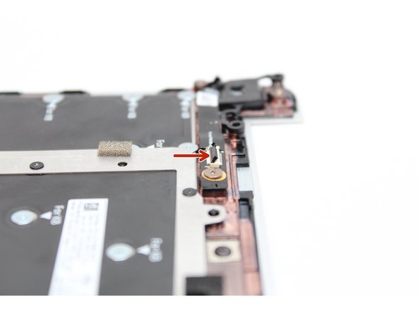
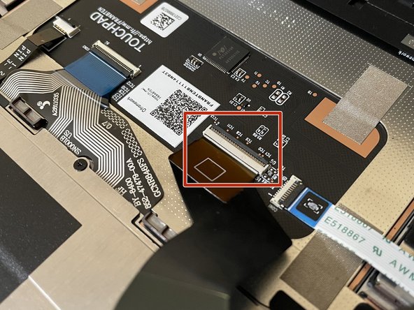
Before closing up the laptop, make sure that the Touchpad end of the Touchpad Cable is fully seated in the receptacle.
-
The cable should be inserted far enough that the white line almost touches the receptacle.
-
If it is not inserted far enough, you'll need to flip up the black latch on the other side of the connector, slide the cable in further, and then close the black latch again.
-
-
-
Flip the Input Cover over the Bottom Cover so that the keyboard is facing up and attach it to the Bottom Cover by aligning the top and bottom edges of both covers.
-
Tip: The covers are magnetic and should fit into one another easily. If you feel any resistance simply lift the Input Cover up and try again.
-
-
-
Close the Framework Laptop and turn it upside down to reveal the five fasteners on the Bottom Cover.
-
Using the T5 bit in the Framework Screwdriver, screw all 5 fasteners back into the Bottom Cover.
-
Be sure to not over-tighten the fasteners.
-


- To purchase a Framework Laptop visit the Framework website.
- Want to learn more about the Framework Laptop? Take a look at our blog.
- If you have any questions or concerns, feel free to reach out to Framework Support.
- To purchase a Framework Laptop visit the Framework website.
- Want to learn more about the Framework Laptop? Take a look at our blog.
- If you have any questions or concerns, feel free to reach out to Framework Support.
Cancel: I did not complete this guide.
9 other people completed this guide.
2 Comments
How can I test (from the terminal, in linux (fedora)) that my fingerprint reader is installed and recognized? What is the driver name? Does the presence of lsusb` -> 'Shenzhen Goodix Technology Co.,Ltd. Goodix USB2.0 MISC' mean that the hardware is installed?
Fred Eisele - Resolved on Release Reply