Introduction
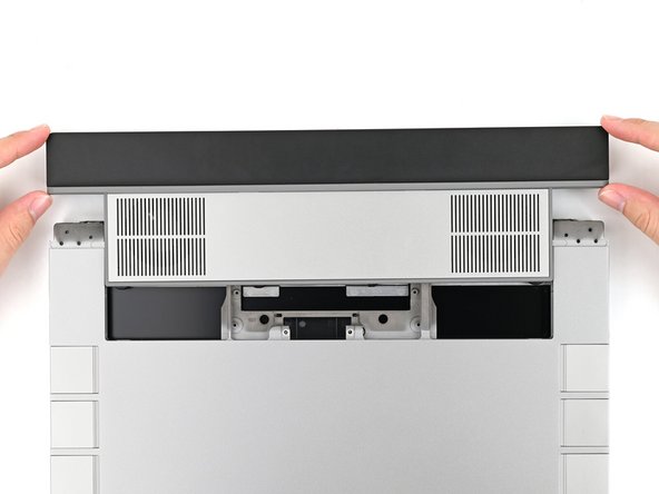
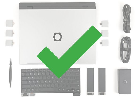
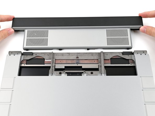
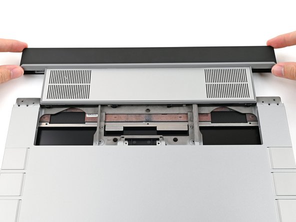
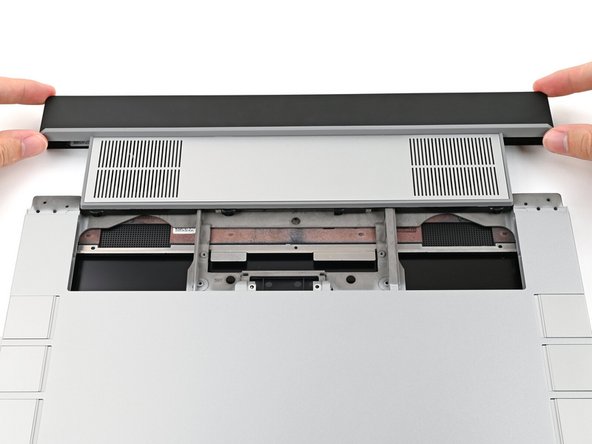
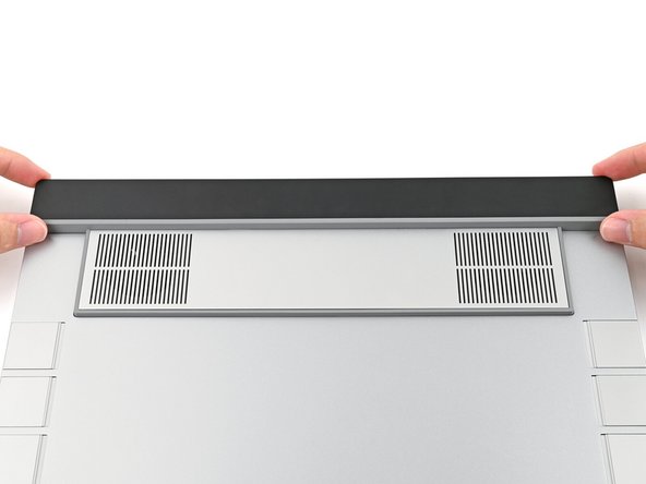
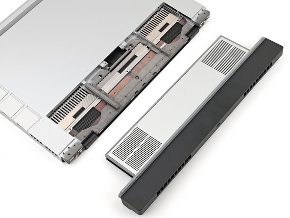
Follow this guide to replace an Expansion Bay Module, i.e., an Expansion Bay Shell or a Graphics Module, in your Framework Laptop 16.
Depending on your configuration, you may only need to remove the Touchpad Module and the keyboard to access the Expansion Bay. This guide shows removing each Input Modules to include all possible configurations.
The hardware portion of this replacement should only take 5-10 minutes. Added time for completion accounts for BIOS download and install.
Tools
Parts
No parts specified.
-
-
If you're upgrading to a new Graphics Module, first make sure your BIOS is up to date with the latest version. You will want to make sure this is done before continuing with the swap.
-
-
-
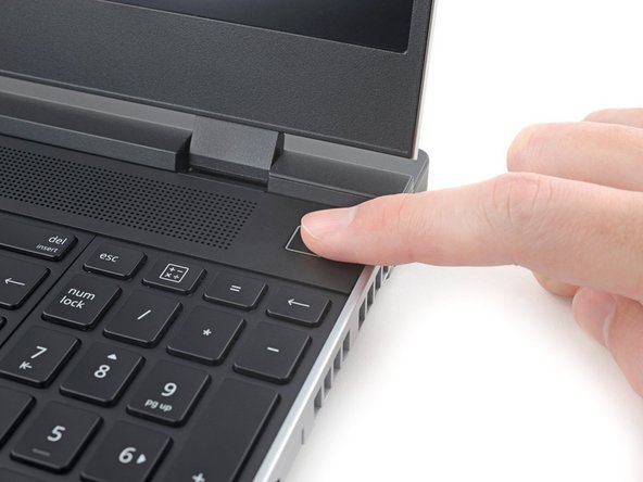
Unplug all cables and fully shut down your laptop.
-
-
-
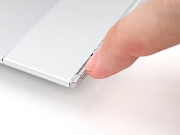
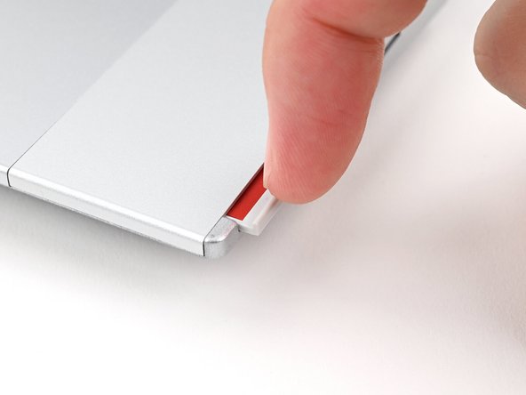
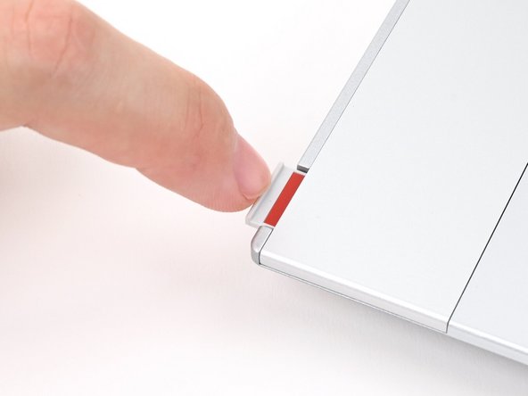
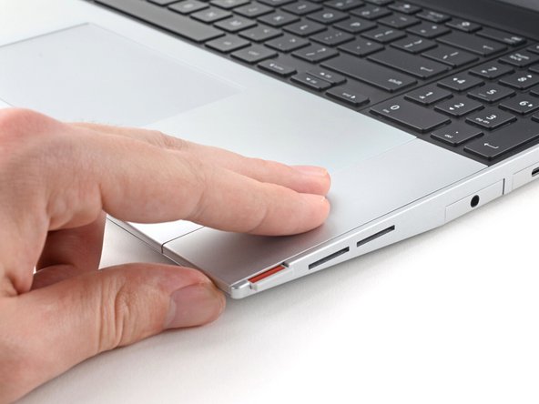
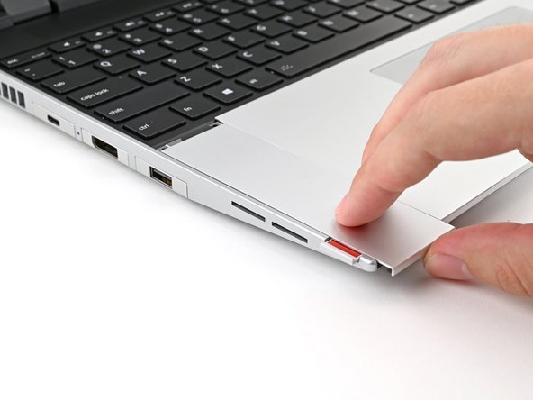
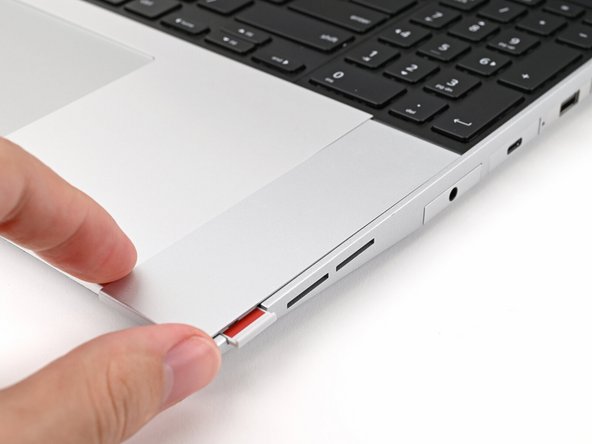
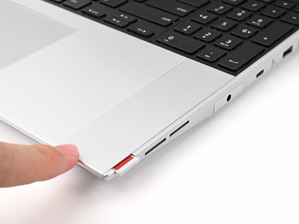
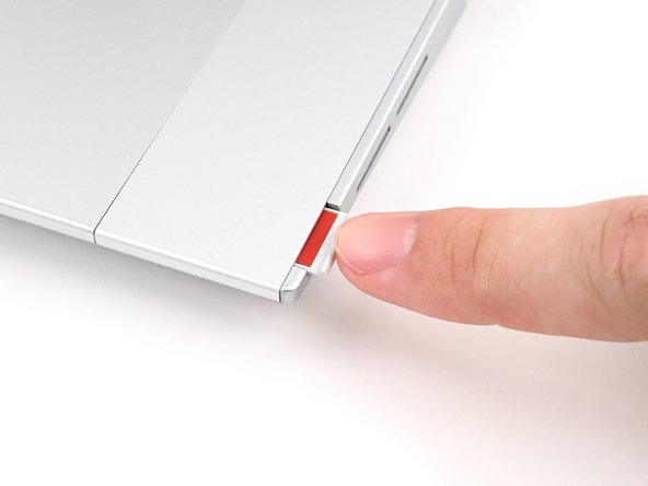
Use your fingernail to pull out the two Input Module latches and unlock them.
-
The latch will show red if it's unlocked.
-
-
-
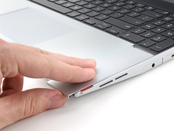
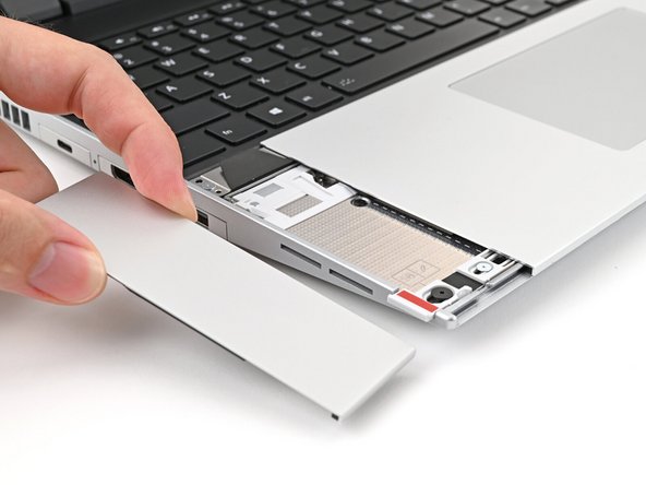
Use your fingers to slide the Touchpad Spacer toward the bottom edge of the laptop and unclip it.
-
If you're having trouble, check if the corresponding Input Module latch is properly unlocked.
-
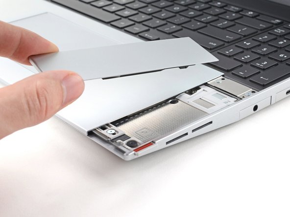
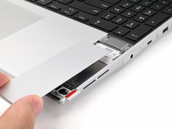
Lift the Touchpad Spacer off the laptop and remove it.
-
-
-
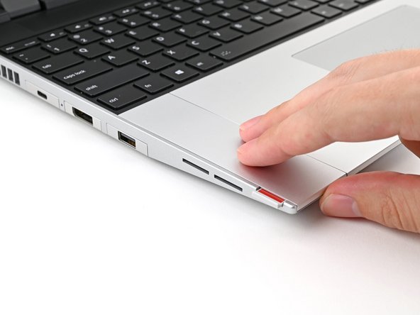
Repeat the same procedure for the other touchpad spacer.
-
-
-
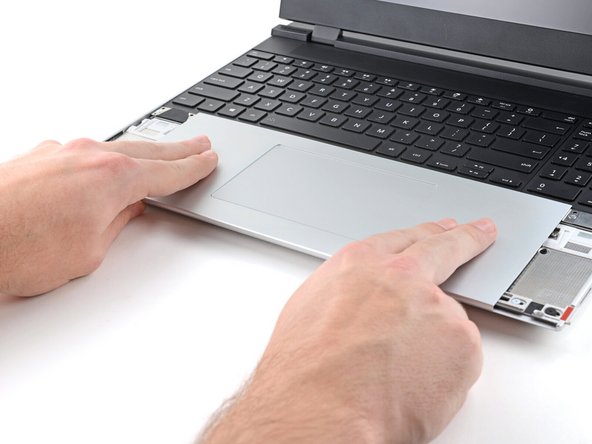
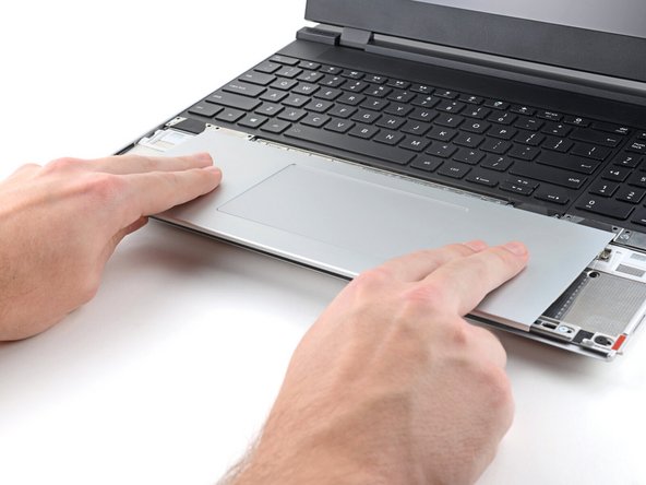
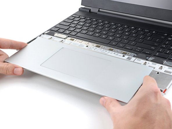
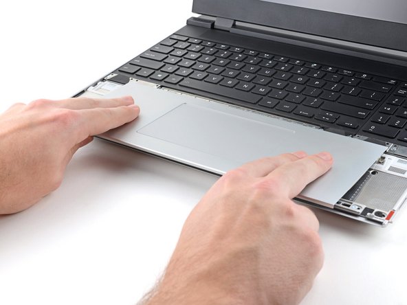
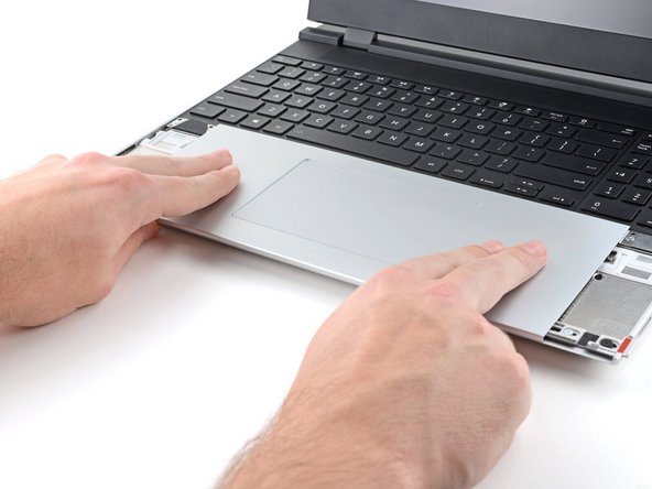
Use your fingers to slide the Touchpad Module toward the bottom edge of the laptop and disconnect it.
-
If you're having trouble, check if the Input Module latches are properly unlocked.
-
Lift the Touchpad Module and remove it.
-
-
-
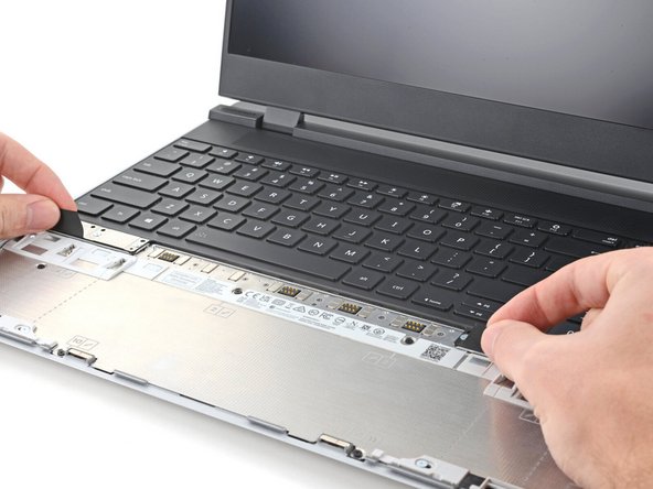
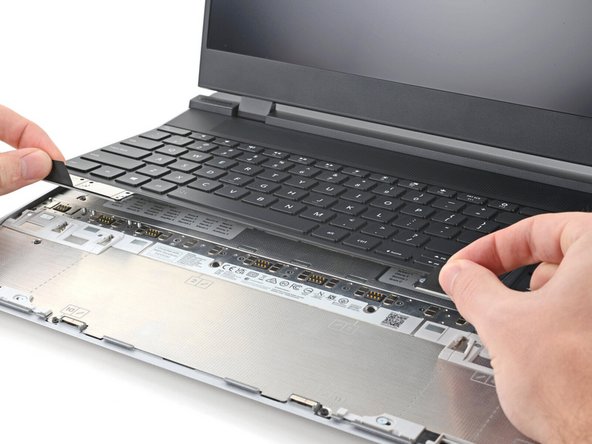
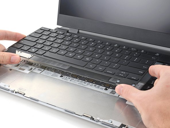
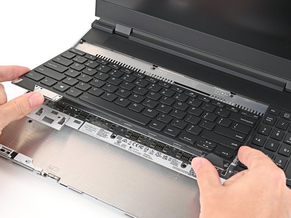
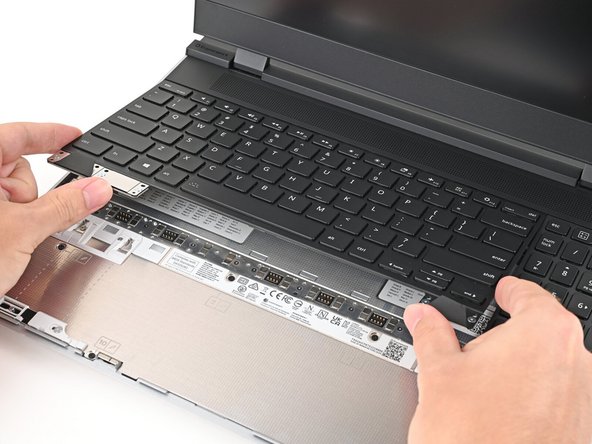
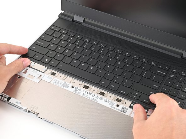
The keyboard is held in place with strong magnets. Apply gradually increasing force to avoid having the keyboard violently eject.
-
Grip the two pull tabs along the bottom of the keyboard and lift until its magnets release.
-
Remove the keyboard.
-
-
-
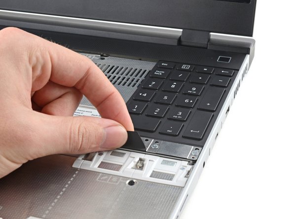
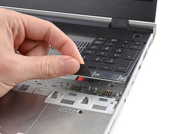
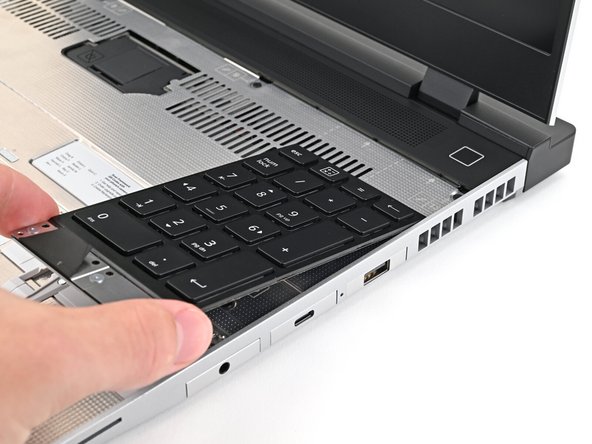
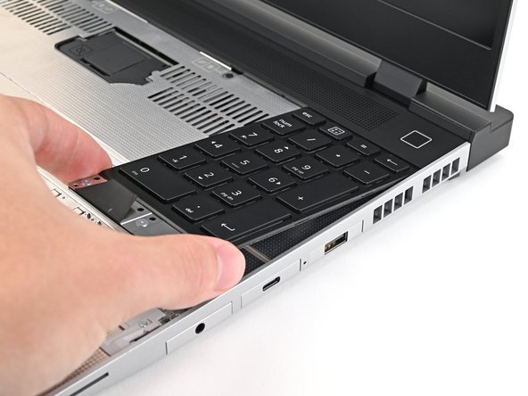
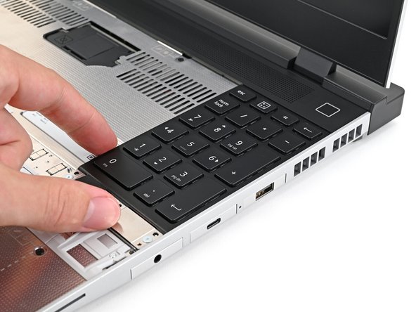
Your Input Module(s) might be different, but the procedure to remove them is the same.
-
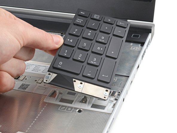
Grip the pull tab at the bottom of the Input Module and lift until its magnets release.
-
Remove the Input Module.
-
Repeat for any remaining Input Modules.
-
-
-
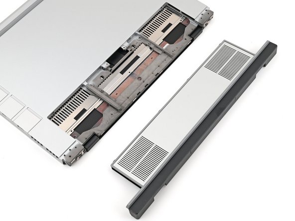
The Expansion Bay can either fit a Graphics Module or the Expansion Bay Shell—the removal and installation procedures for both are nearly identical.
-
The following instructions will point out any differences.
-
-
-
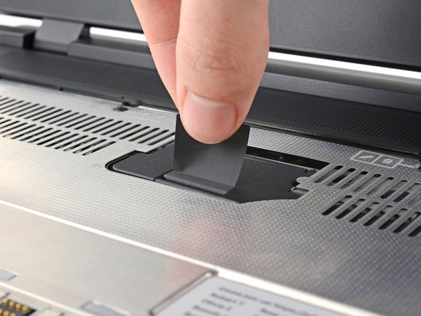
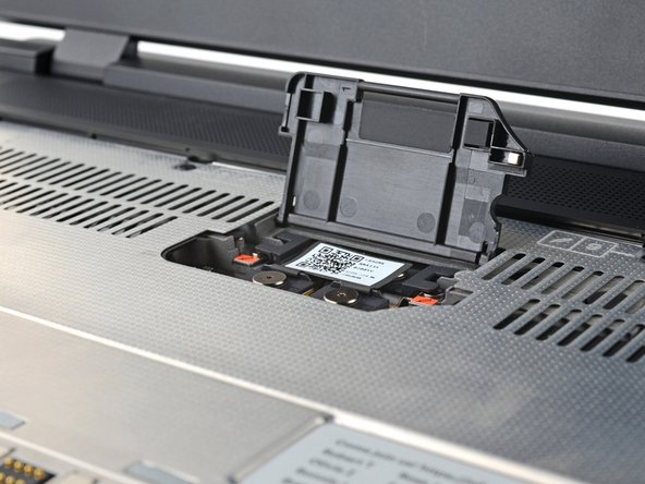
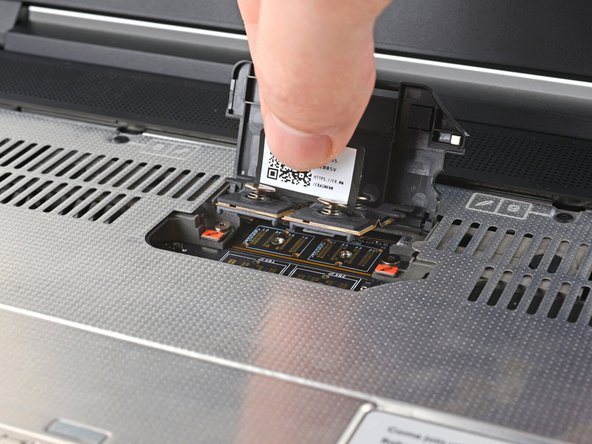
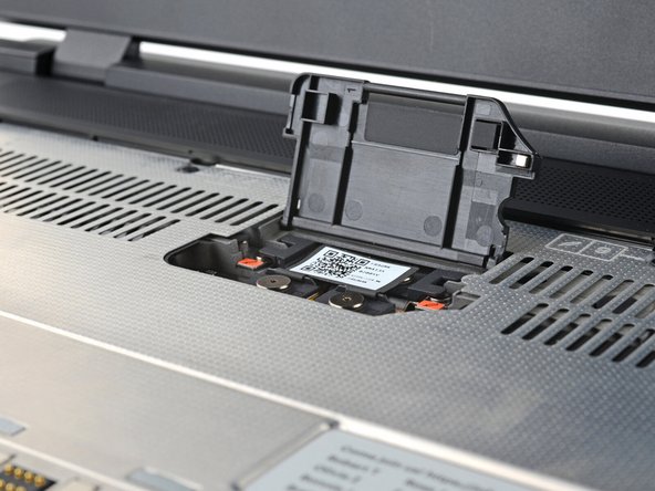
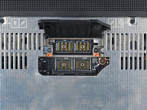
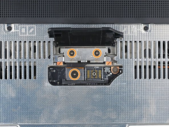
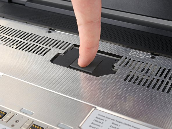
Lift the interposer door by its black pull tab and let it rest upright.
-
-
-
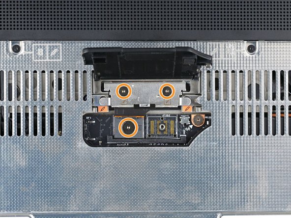
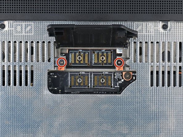
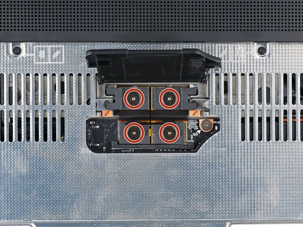
If you have the Graphics Module installed, your interposer will have four screws. If you have the Expansion Bay Shell installed, you'll have three screws instead.
-
If you have the Graphics Module, use your Framework Screwdriver to loosen the four captive T5 Torx screws securing the interposer.
-
If you have the Expansion Bay Shell, use your Framework Screwdriver to loosen the three captive T5 Torx screws securing the interposer.
-
-
-
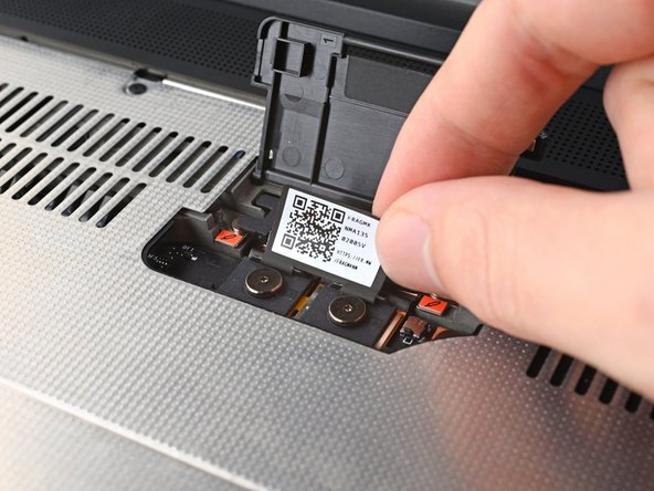
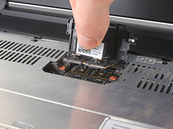
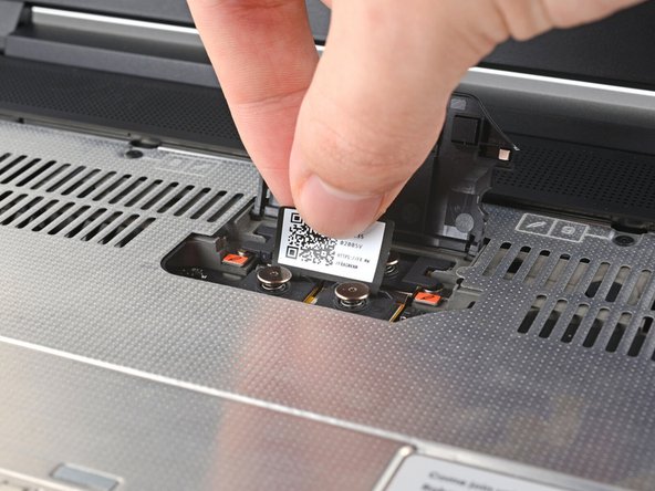
Lift the interposer by its pull tab and remove it.
-
-
-
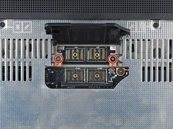
Use your Framework Screwdriver to loosen the two captive T5 Torx screws securing the Expansion Bay Module.
-
Close the interposer door before continuing.
-
-
-
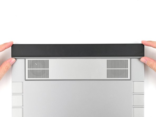
Close your laptop and flip it over.
-
Slide the Expansion Bay Module out of the laptop and remove it.
-
The module should slide out easily. If you feel any resistance, check that the screws holding it in place are fully loosened.
-
-
-
Congratulations on completing disassembly! The remaining steps will show how to reassemble your Framework Laptop.
-
-
-
Align the Expansion Bay Module with its slot in the laptop.
-
Check that the module sits evenly with the rail on the outside edges of the slot.
-
Check that the two center rails are threaded between the fans.
-
-
-
While keeping the module level with the laptop, slide it into its slot.
-
The module should slide in easily. If you feel any resistance, pull the module out and realign it.
-
You should hear an audible "click" when the module's clips snap into place.
-
-
-
Flip over the laptop and open it.
-
Lift the interposer door by its black pull tab and let it rest upright.
-
-
-
Use your Framework Screwdriver to tighten the two captive T5 Torx screws securing the Expansion Bay Module.
-
-
-
Place the interposer over its spot between the Mainboard and the Expansion Bay.
-
Depending on if you're installing a Graphics Module or the Expansion Bay Shell, the interposer should be oriented so either rubber grommets or metal tabs cover the Expansion Bay screws.
-
-
-
If you have the Graphics Module installed, your interposer will have four screws. If you have the Expansion Bay Shell installed, you'll have three screws instead.
-
If you have the Graphics Module, use your Framework Screwdriver to tighten the four captive T5 Torx screws securing the interposer.
-
If you have the Expansion Bay Shell, use your Framework Screwdriver to tighten the three captive T5 Torx screws securing the interposer.
-
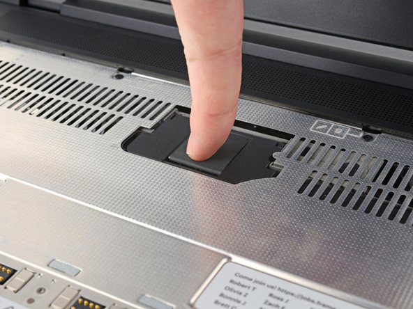
Close the interposer door.
-
-
-
Your Input Module(s) might be different, but the procedure to remove them is the same.
-
Align the top edge of the Input Module with the top edge of the laptop.
-
Lay the Input Module on the laptop and let the magnets pull the keyboard into place
-
Make sure the Input Module is seated properly on its alignment pegs and sits flush with the edges of the laptop.
-
Repeat for any remaining Input Modules.
-
-
-
Align the top edge of the keyboard with the top edge of the laptop.
-
Lay the keyboard on the laptop and let the magnets pull the keyboard into place
-
Make sure the keyboard is seated properly on its alignment pegs and sits flush with the edges of the laptop.
-
-
-
Place the Touchpad Module flat on its cutout so its clips are properly aligned.
-
Press the Touchpad Module down and slide it into place so it lines up evenly with the bottom edge of the laptop.
-
-
-
Place the Touchpad Spacer over its spot on the laptop with the bottom edge overhanging slightly.
-
Slide the Touchpad Spacer towards the top of the laptop to secure it.
-
Repeat the same procedure for the other Touchpad Spacer.
-
-
-
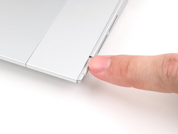
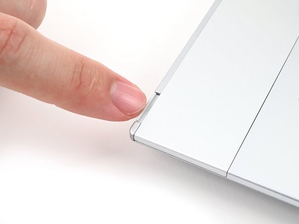
Push the Input Module latches back into place to lock them.
-
-
If you need help, contact Framework support.
If you need help, contact Framework support.
Cancel: I did not complete this guide.
One other person completed this guide.


