Introduction
Follow this guide to remove and replace the display in your Framework Laptop 12.
The display (aka display panel or screen) is the LCD panel in your laptop. The display also has the touchscreen and stylus functionality built into the part. If you crack your display or if the touchscreen doesn't work, you may need to replace this part.
You'll encounter some component terms in this guide:
- The Display Cover is the plastic bezel strip below the display.
- The Top Cover is the plastic shell that houses the display.
Tools
Parts
No parts specified.
-
-
Before you begin repairs, unplug your laptop and shut it down from the operating system. This ensures that the laptop isn't in standby/suspend mode.
-
The indicator LEDs along the edges should be unlit. The laptop should be silent.
-
If you accidentally turn on the laptop during repair, hold the power button down for 10 seconds to shut it down.
-
Make sure your Framework Screwdriver has the T5 Torx bit (labeled as T-5) facing outwards. If it's not, pull the bit out and flip it.
-
-
-
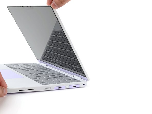
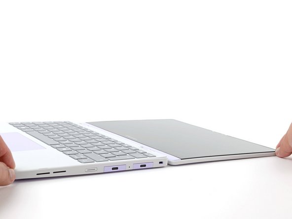
Open the laptop lid so that both the screen and the base lie flat on your work surface.
-
-
-
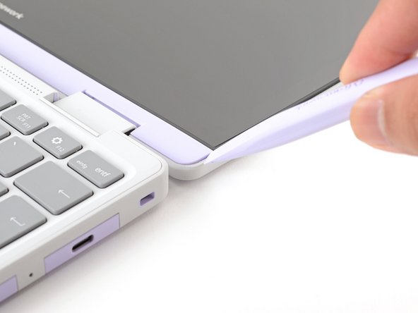
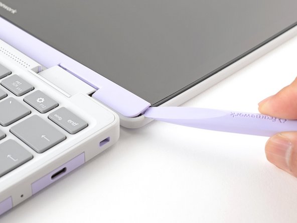
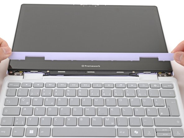
The Display Cover is held in place with magnets along the top edge and clips along the remaining edges.
-
Use the flat end of your Framework Screwdriver to pry up the right edge of the Display Cover.
-
-
-
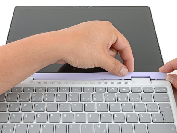
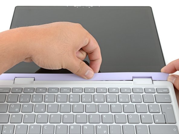
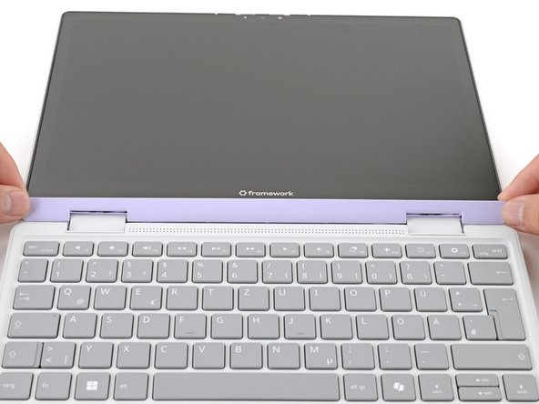
Slide your fingers under the top edge of the Display Cover to release it from the laptop.
-
-
-
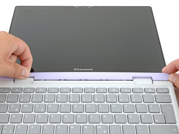
Remove the Display Cover.
-
-
-
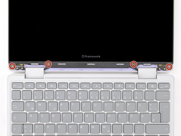
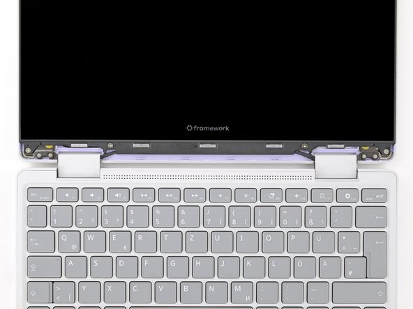
Use your Framework Screwdriver to remove the four 3.3 mm‑long T5 Torx screws securing the display to the Top Cover.
-
These screws are not captive. Store them in a safe location for reassembly.
-
-
-
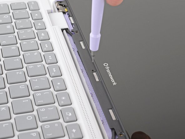
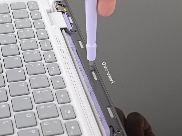
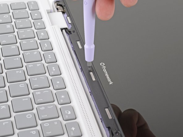
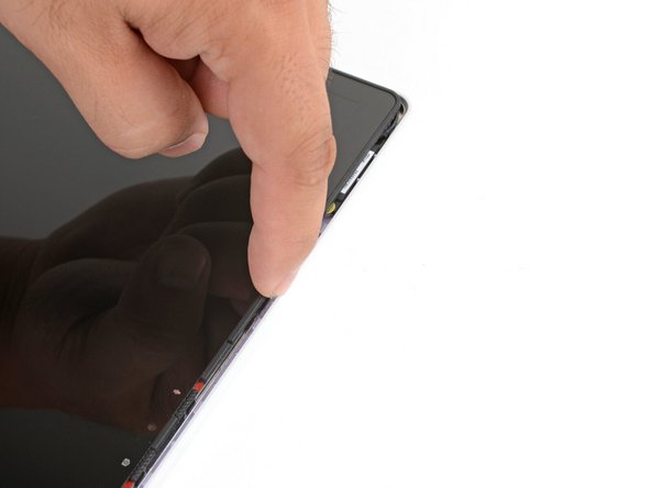
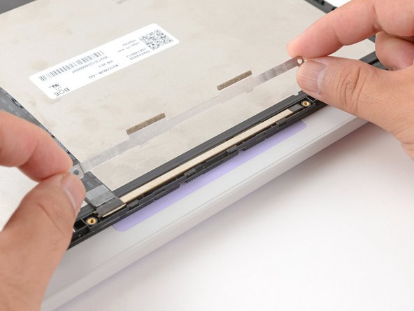
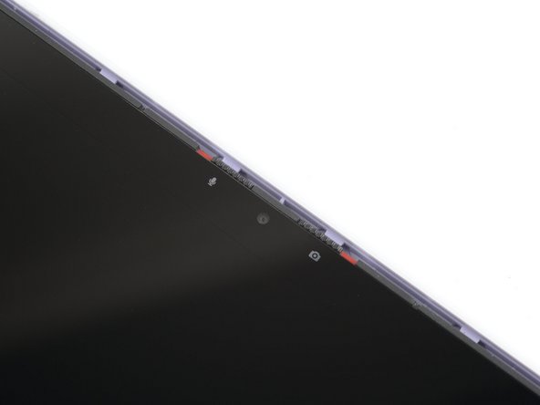
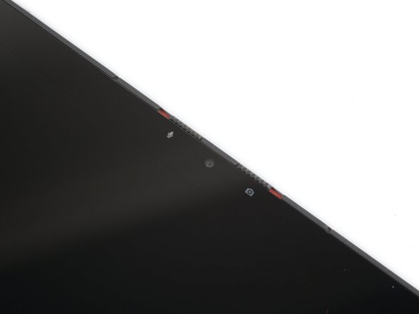
Insert the bit end of your Framework Screwdriver into the small hole on the display, below the Framework logo.
-
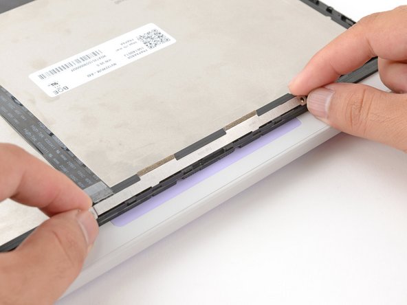
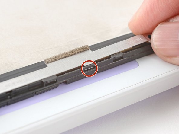
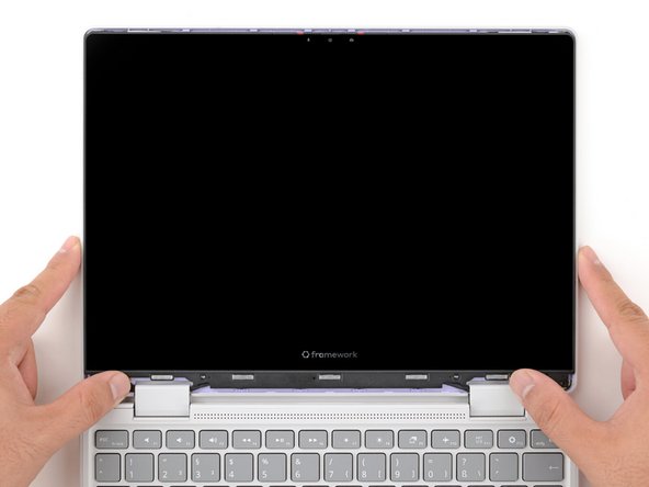
Slide the display down towards the hinge edge to release the tabs holding the top edge of the display in place.
-
-
-
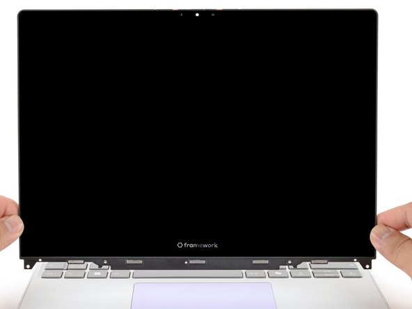
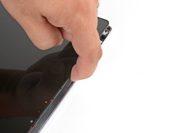
Use your fingers to lift the top edge of the display from the Top Cover.
-
-
-
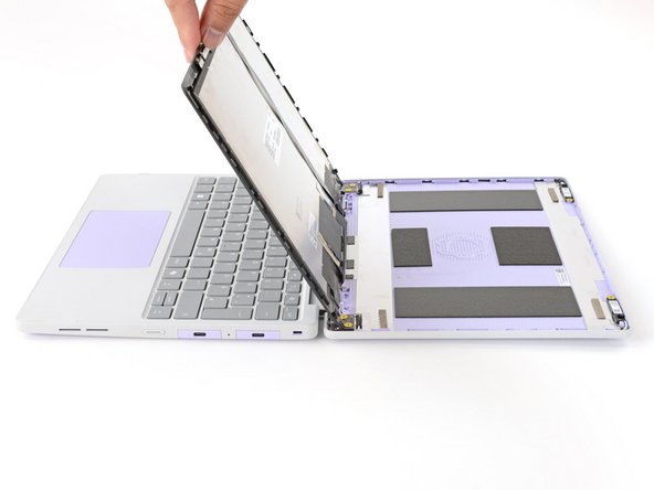
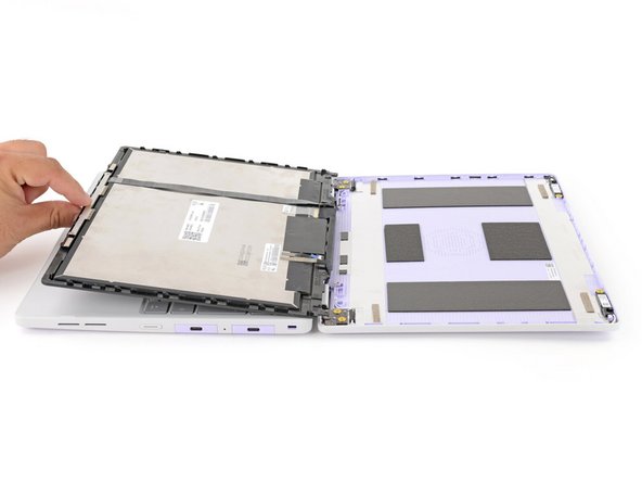
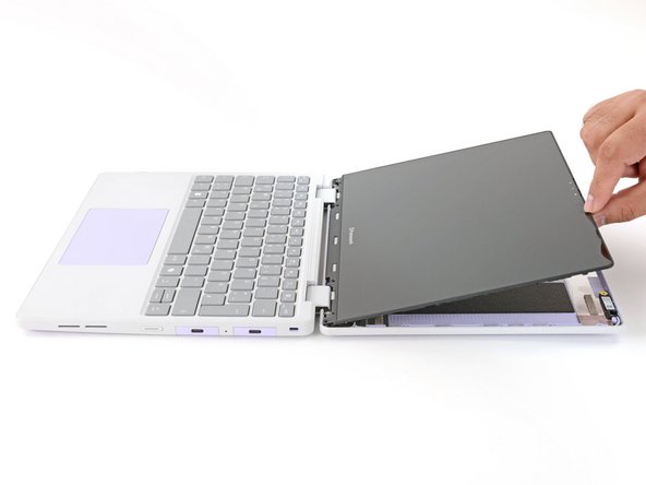
Use your fingers to carefully swing the display over so it lies on top of the keyboard.
-
-
-
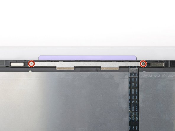
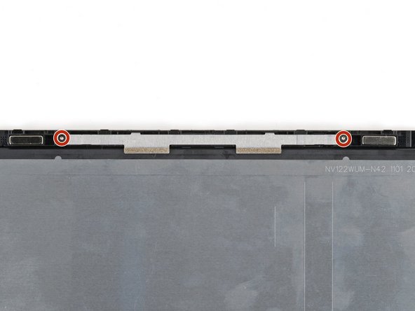
Use your Framework Screwdriver to remove the two 3.3 mm‑long T5 Torx screws securing the webcam bracket on the top edge behind the display.
-
These screws are not captive. Store them in a safe location for reassembly.
-
-
-
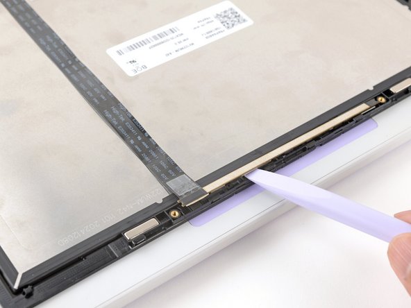
Lift and remove the webcam bracket.
-
-
-
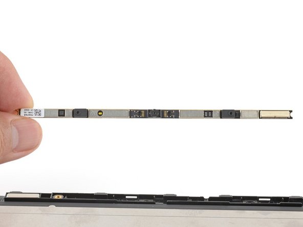
Use the flat end of your Framework Screwdriver to lift the webcam out of its recess.
-
Avoid touching the black camera module near the center of the webcam.
-
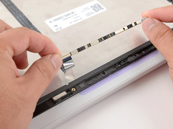
Flip the webcam over and gently hold it down with your fingers.
-
-
-
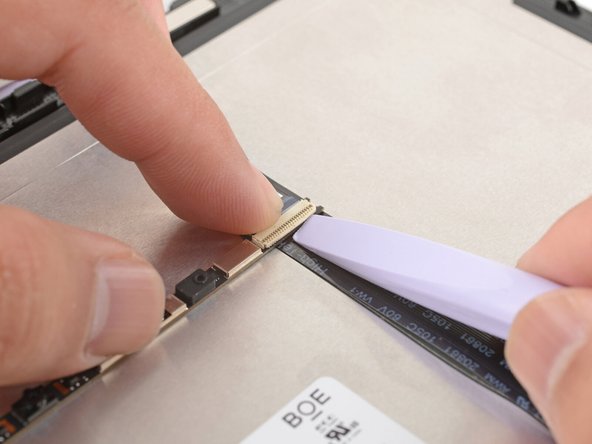
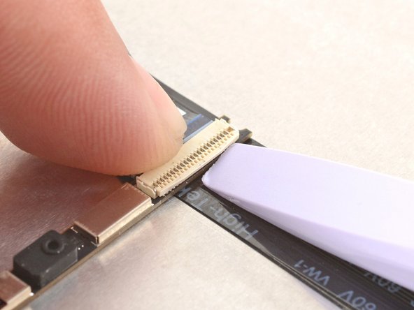
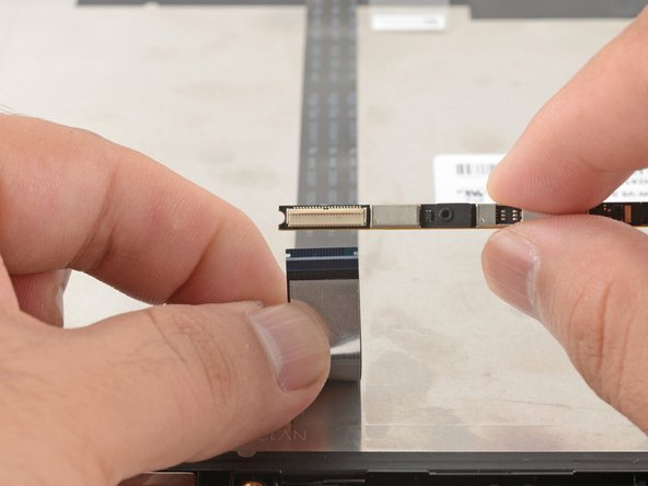
Use the flat end of your Framework Screwdriver or a fingernail to gently pry up the locking tab on the webcam cable ZIF connector.
-
-
-
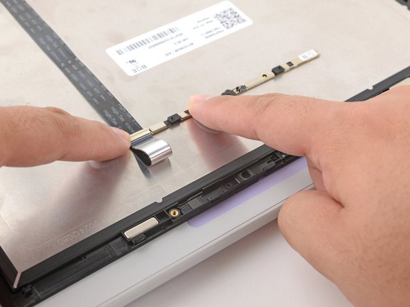
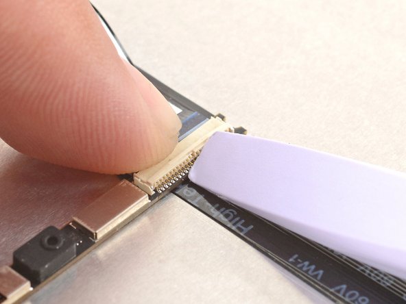
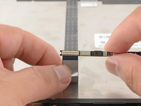
Slide the webcam cable out of its connector.
-
Remove the webcam.
-
-
-
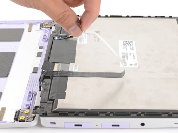
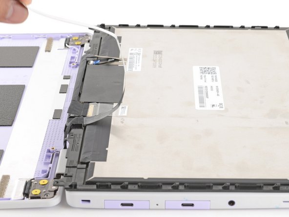
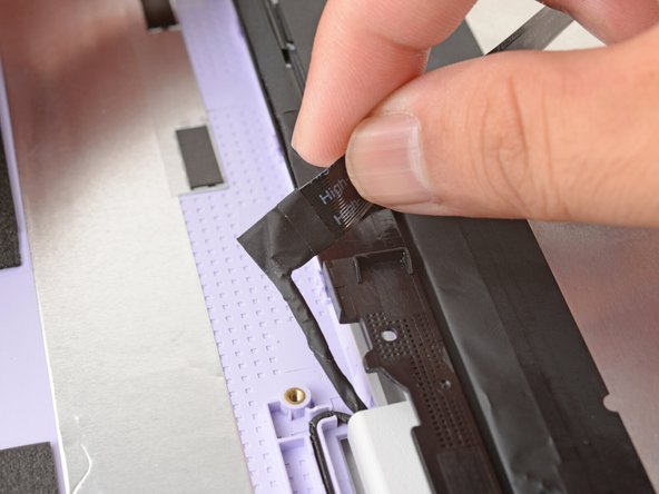
The webcam cable is lightly adhered to the display.
-
Grab the webcam cable with your fingers and slowly peel it away from the display.
-
Carefully move the cable off of the display.
-
-
-
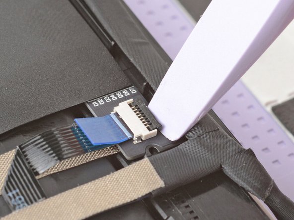
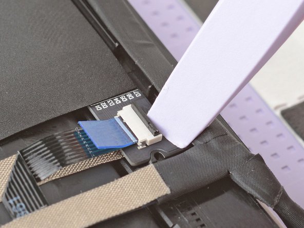
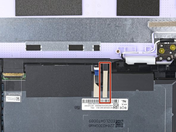
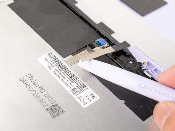
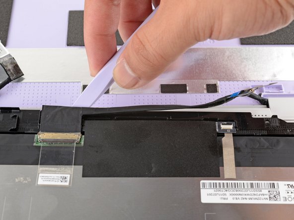
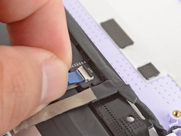
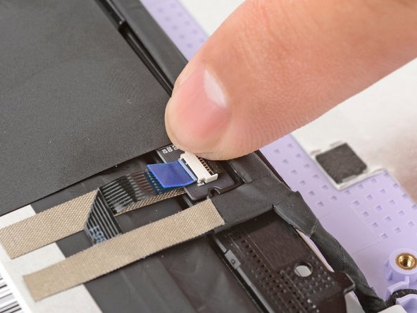
Use the flat end of your Framework Screwdriver or a fingernail to gently pry up the locking tab on the touch control ZIF connector near the hinge edge of the display.
-
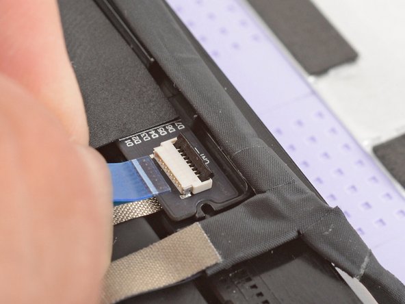
Use your fingers to grab the touch control cable by the blue tab and slide the cable out of the connector.
-
-
-
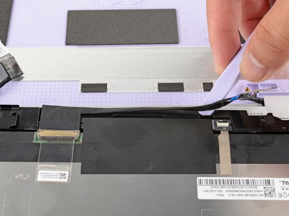
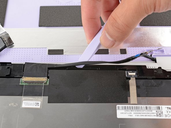
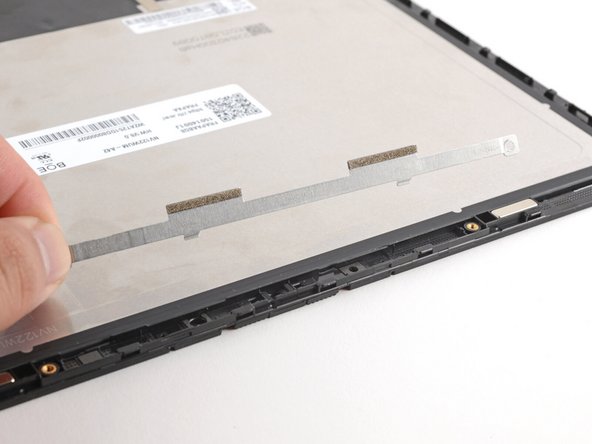
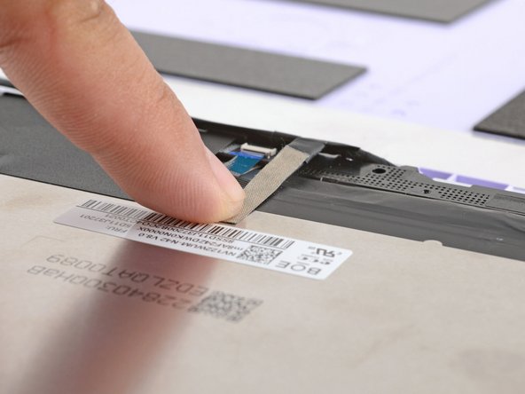
Slide the flat end of your Framework Screwdriver under the grounding tape securing the display cable.
-
Lift slowly to separate the tape from the display.
-
Keep this tape clean and intact during your repair. You'll use it to attach the cable during reassembly.
-
-
-
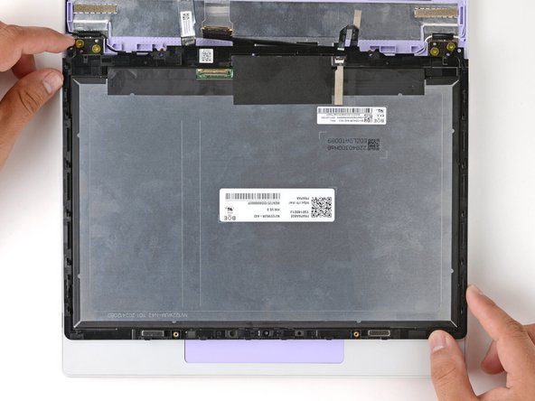
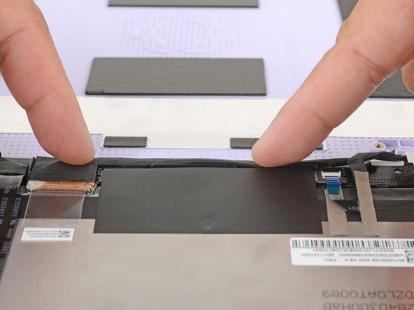
The display cable is lightly adhered to the bottom edge of the display.
-
Slide the flat end of your Framework Screwdriver under the length of the display cable to separate it from the display.
-
-
-
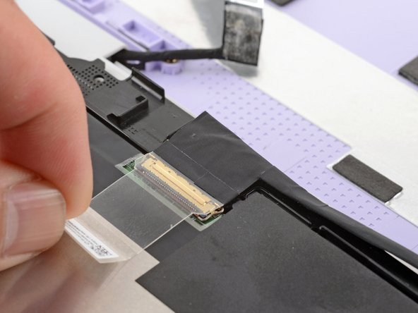
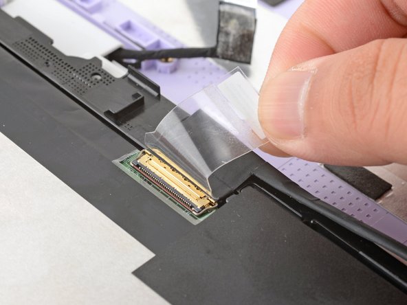
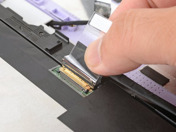
Use your fingers to peel up the clear tab covering the display cable connector.
-
-
-
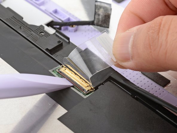
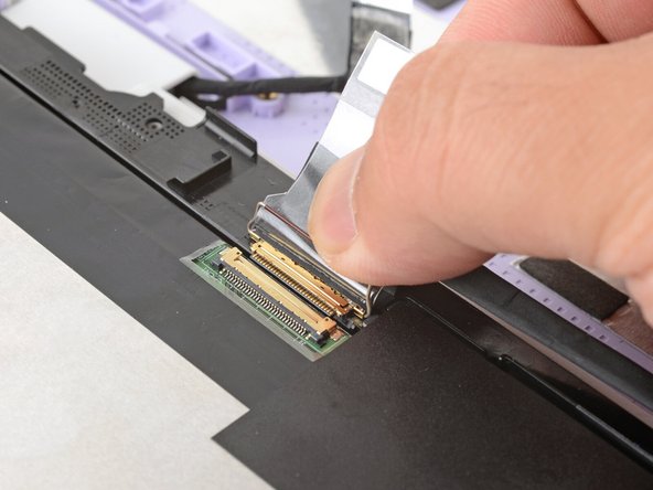
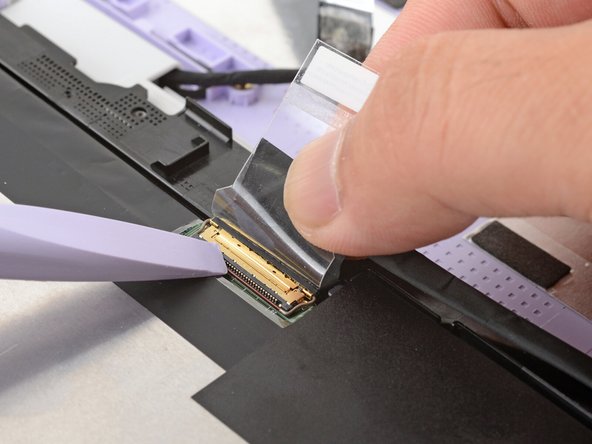
Use the flat end of your Framework Screwdriver to flip up the locking bar around the display connector.
-
-
-
Make sure the locking bar doesn't fall back in place while you disconnect the display cable.
-
Grasp the display cable near the connector and slide it out of the connector.
-
If you have trouble getting the cable to slide out, gently wiggle it to loosen the connection.
-
-
-
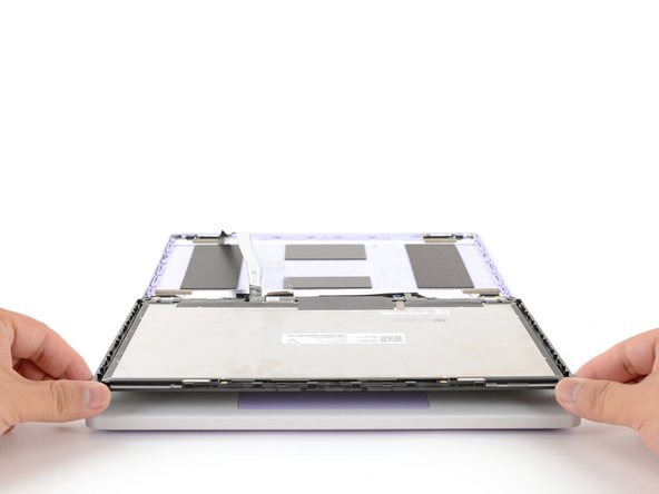
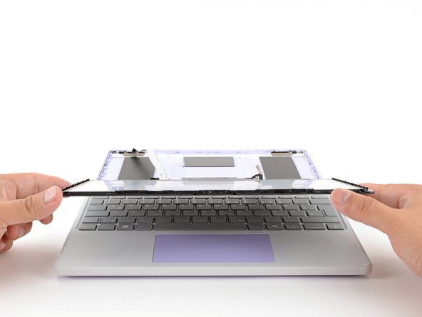
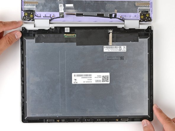
Carefully lift and remove the display.
-
-
-
Congratulations on completing disassembly! The remaining steps will show how to reassemble your Framework Laptop.
-
-
-
The Framework Display Kit comes with an extra webcam bracket. If you're not using this kit to repair your display, skip this step.
-
Inspect the replacement display and carefully peel off any protective liners.
-
Use your Framework Screwdriver to remove the two 3.3 mm‑long T5 Torx screws securing the webcam bracket on the replacement display.
-
Remove the webcam bracket.
-
Remove any protective liners that may be in the webcam recess. The liners are normally clear or colored plastic films that easily detach.
-
You can use the replacement bracket and screws, or you can reuse your existing ones.
-
-
-
Carefully lay the display screen-side down on top of the Input Cover. The edge with the webcam should lay near the touchpad edge.
-
The Input Cover magnets will align the display to itself.
-
Use your fingers to slide the display off the Input Cover magnets towards the hinge edge so that the display cable can reach its connector.
-
-
-
Use your fingers to grab the display cable by the clear tab and the locking bar.
-
Align the display cable with its connector and slide it in until it's fully seated.
-
-
-
Swing the locking bar down over the connector.
-
If the locking bar can't swing all the way down around the connector, you'll need to insert the cable deeper into the connector.
-
Lay the clear tab over the connector and press it onto the display.
-
-
-
Slide the touch control cable into the ZIF connector up to the printed line on the cable.
-
Use your finger to flip down and gently press the locking tab in place.
-
-
-
Use your finger to press the display cable grounding tape onto the metal back of the display.
-
Use your fingers to press the display cable onto the display.
-
-
-
Use your fingers to press the webcam cable onto the display.
-
-
-
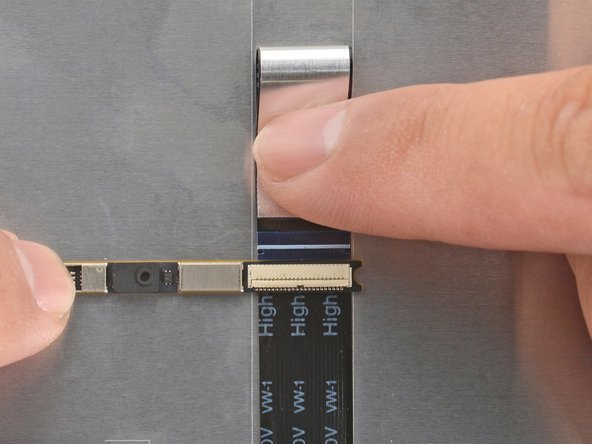
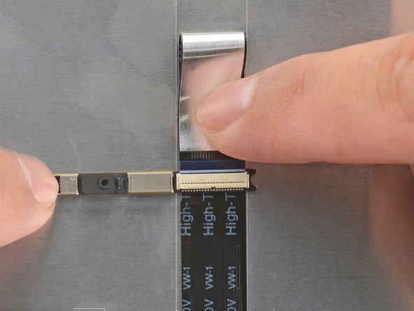
Bend an inch (2.5 cm) of the webcam cable over so that the shiny side is facing you.
-
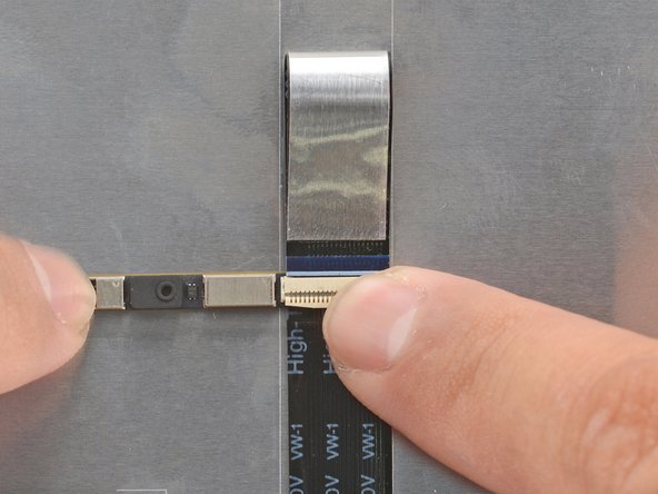
Slide the webcam cable into the ZIF connector up to the printed line on the cable.
-
Use your finger to flip down and gently press the locking tab in place.
-
-
-
Use your fingers to flip the webcam back into its recess in the Top Cover.
-
-
-
Align the webcam bracket to the Top Cover and lay it in place.
-
Make sure the tabs on the top edge of the webcam bracket sit in their slots on the top edge of the display.
-
-
-
Use your Framework Screwdriver to install the two 3.3 mm‑long T5 Torx screws to secure the webcam.
-
-
-
Use your fingers to carefully swing the display over so it lies on top of the Top Cover.
-
-
-
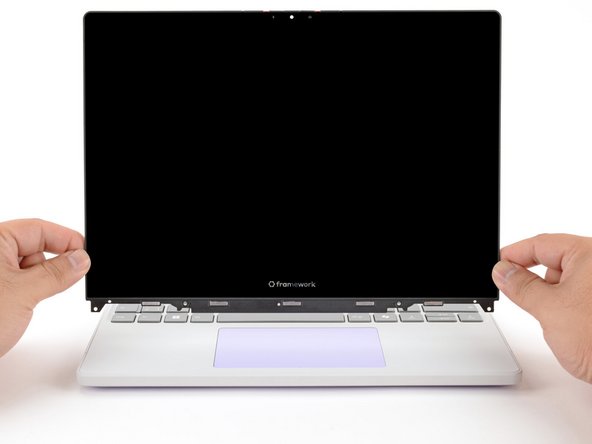
Align the display in the Top Cover such that the top edge of the display is slightly below the top edge of the Top Cover.
-
Use your fingers to slide the display upwards to latch the tabs on the top edge of the display.
-
The top edge shouldn't have any gaps when the display's in place.
-
-
-
Use your Framework Screwdriver to install the four 3.3 mm‑long T5 Torx screws to secure the display to the Top Cover.
-
Tighten the screws until they're snug. Don't over-tighten them, or you may damage the screw tabs.
-
-
-
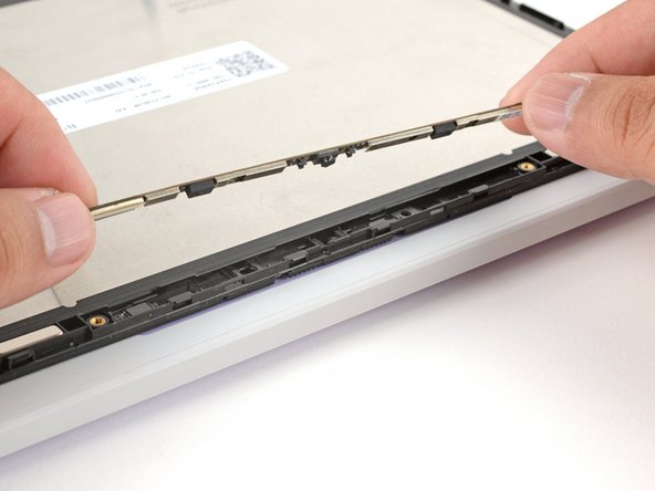
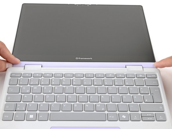
Align the Display Cover to the bottom of the display.
-
-
-
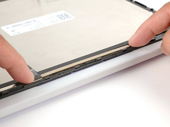
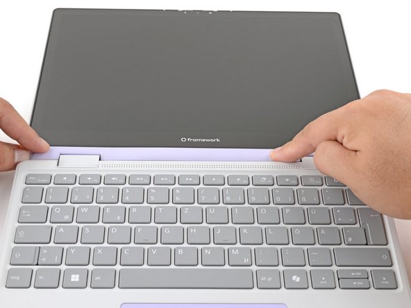
Use your finger to press along the length of the Display Cover to snap it onto the laptop.
-
Make sure all the clips along the left, top, and right edges are fully seated.
-


You finished fixing your Framework Laptop!
Take your e-waste to an R2 or e-Stewards certified recycler.
If you need help, contact Framework support.
You finished fixing your Framework Laptop!
Take your e-waste to an R2 or e-Stewards certified recycler.
If you need help, contact Framework support.
Cancel: I did not complete this guide.
One other person completed this guide.