Introduction
Use this guide to remove and replace the antennas in your Framework Desktop.
Parts
No parts specified.
-
-
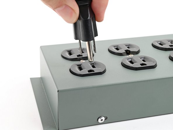
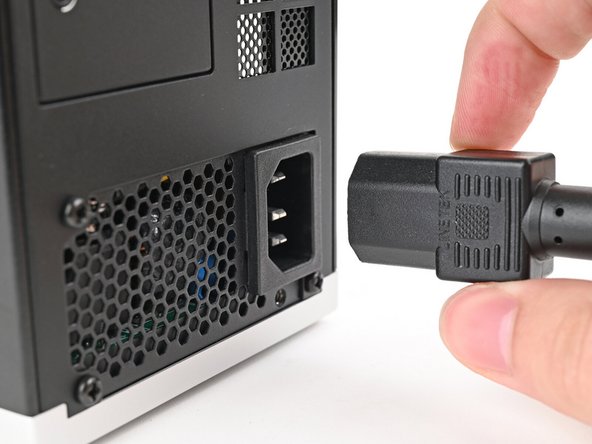
Before you begin repairs, shut down your Desktop from the operating system and unplug it.
-
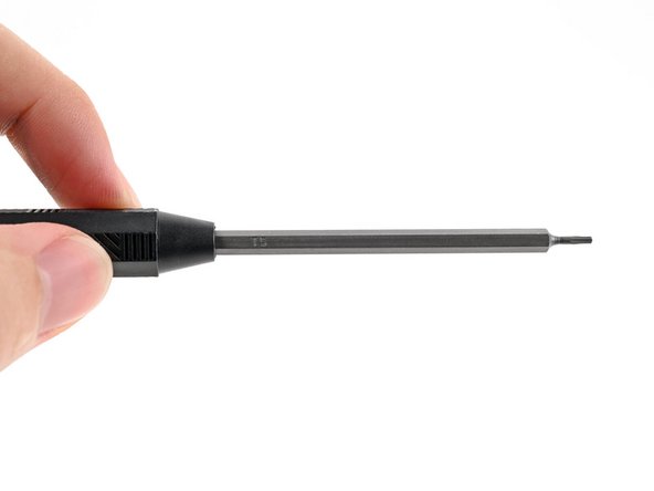
Make sure your Framework Desktop Screwdriver has the T5 Torx bit (labeled as T5) facing outwards. If it's not, pull the bit out and flip it.
-
-
-
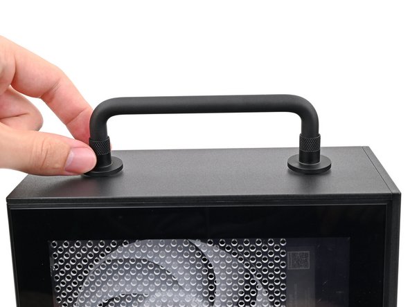
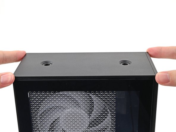
If you installed the Handle on your Desktop, follow this step. Otherwise, skip it.
-
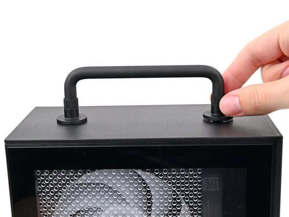
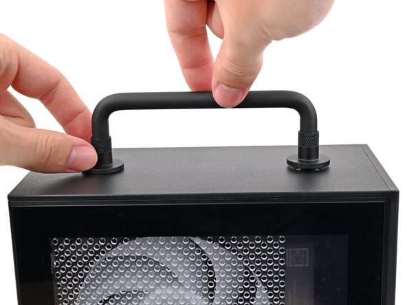
Rotate the Handle's screw threads counterclockwise on both sides until it comes free.
-
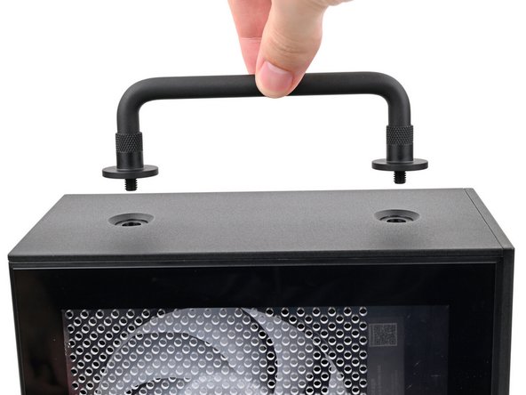
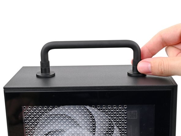
Remove the Handle.
-
-
-
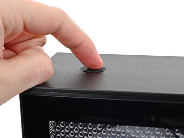
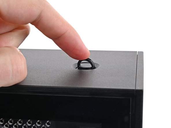
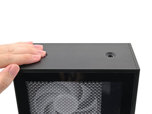
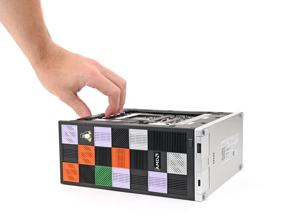
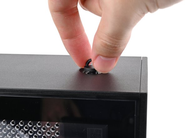
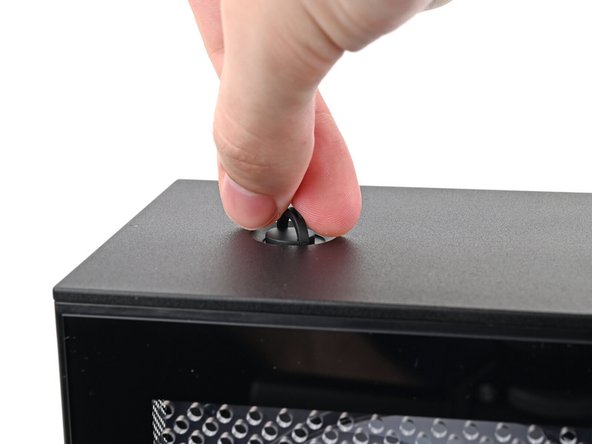
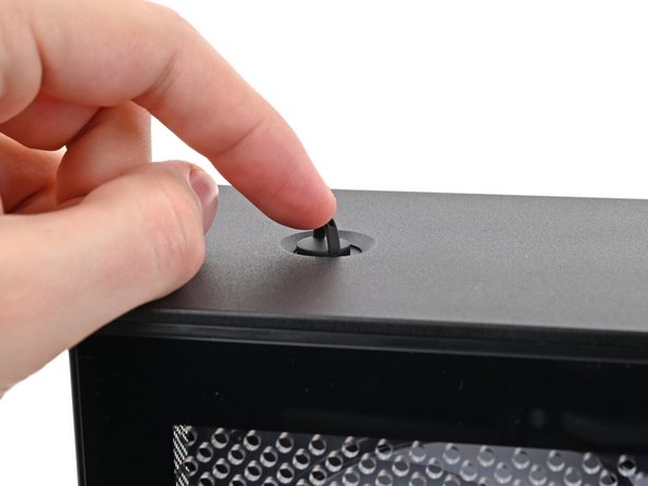
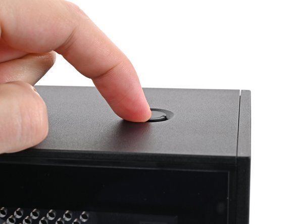
Use your finger to lift up the two D-rings on the Top Panel screws.
-
-
-
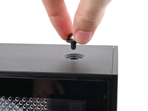
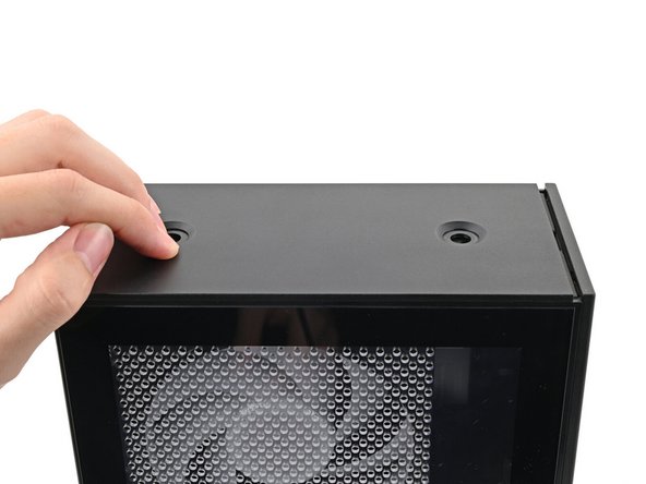
Use your fingers to twist the screw counter-clockwise and loosen it.
-
Remove the Top Panel screw.
-
-
-
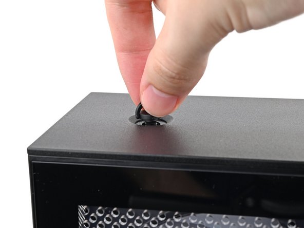
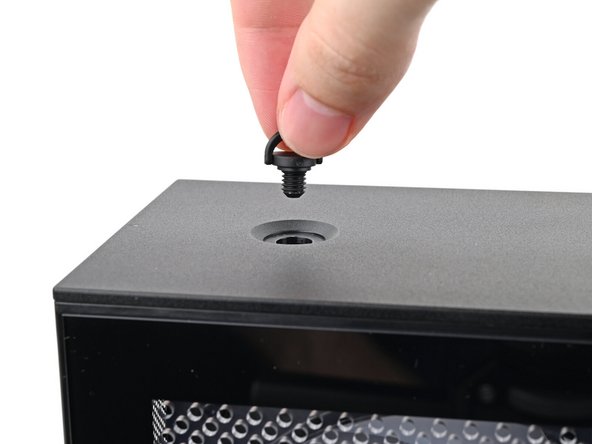
Repeat the same procedure for the other Top Panel screw.
-
-
-
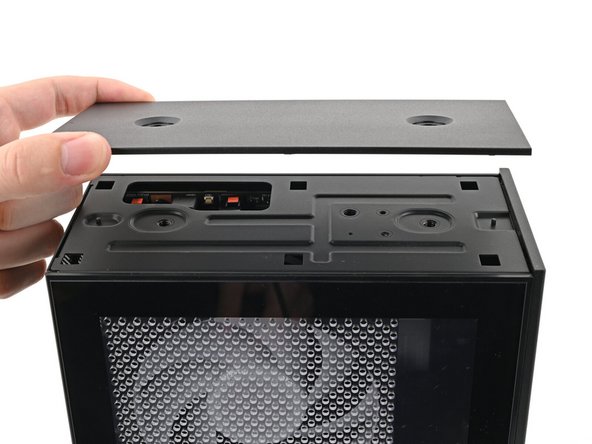
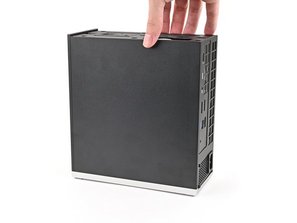
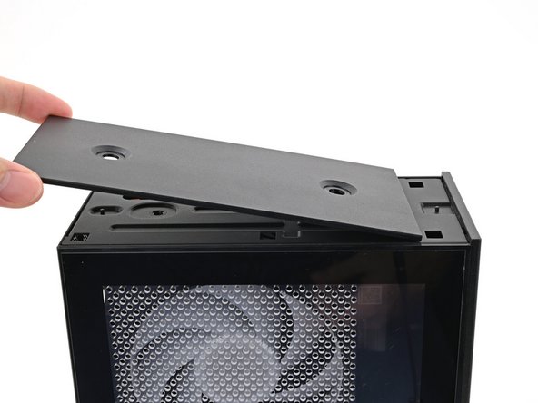
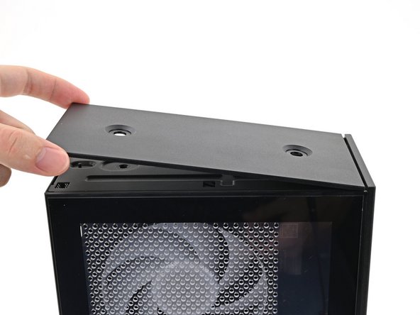
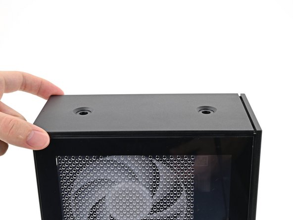
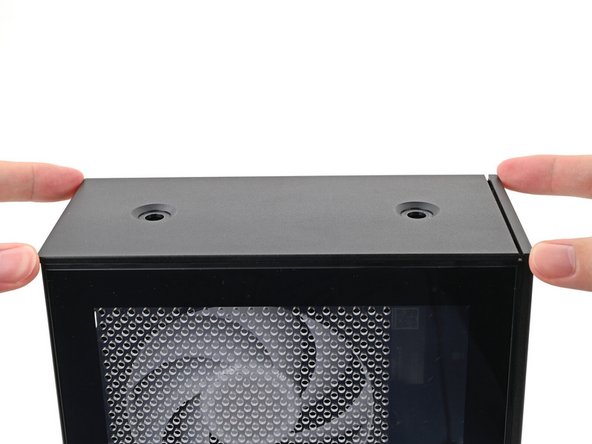
Slide the Top Panel towards the rear of the computer to release the clips securing it to the chassis.
-
If you're having a hard time gripping the Top Panel, use the screw holes to get a better handhold.
-
Lift the Top Panel off the chassis and remove it.
-
-
-
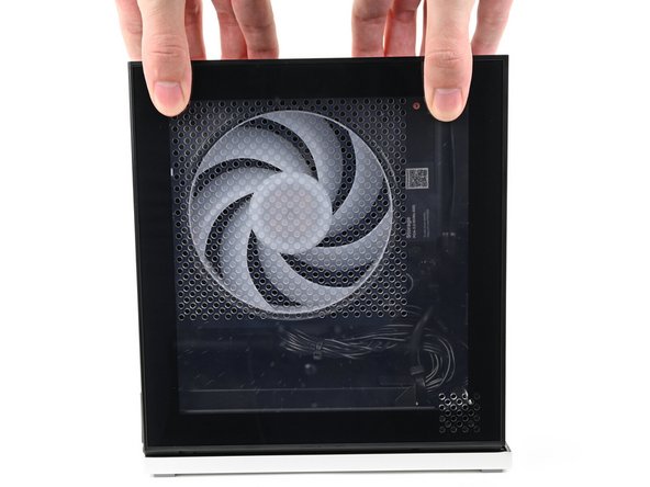
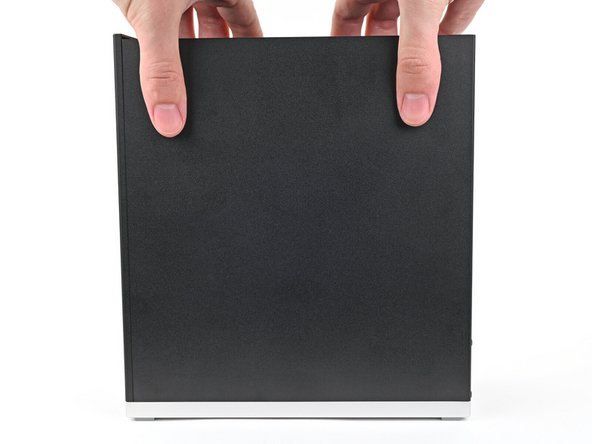
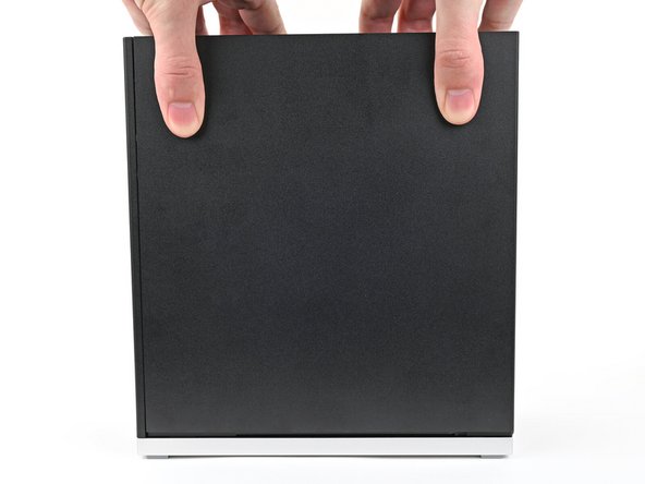
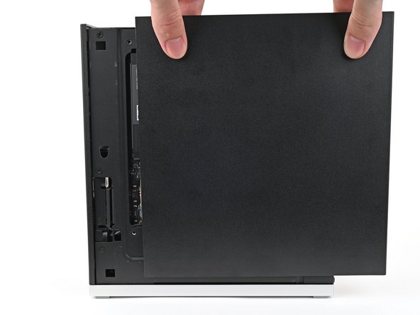
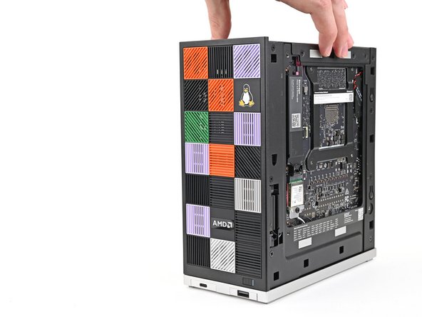
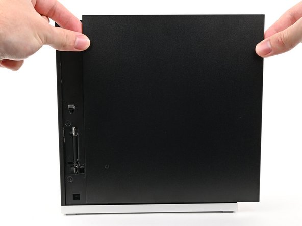
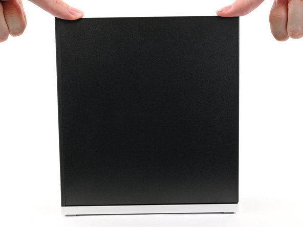
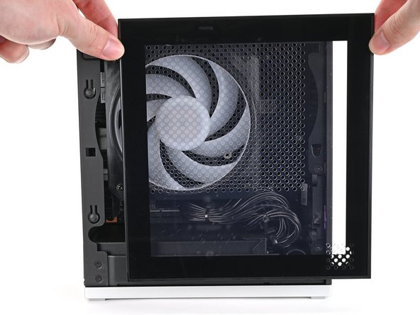
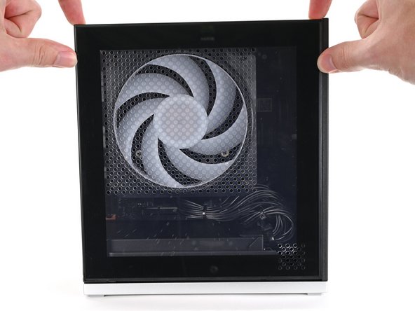
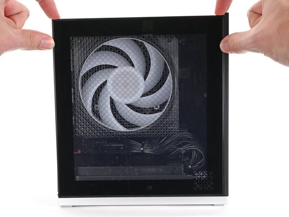
Use your fingers to grip the top of the Left Panel and slide it upward to release its clips.
-
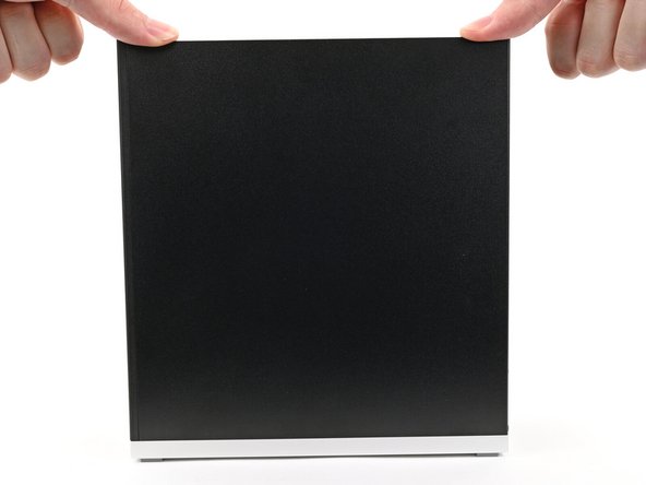
Remove the Left Panel.
-
-
-
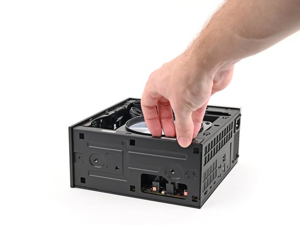
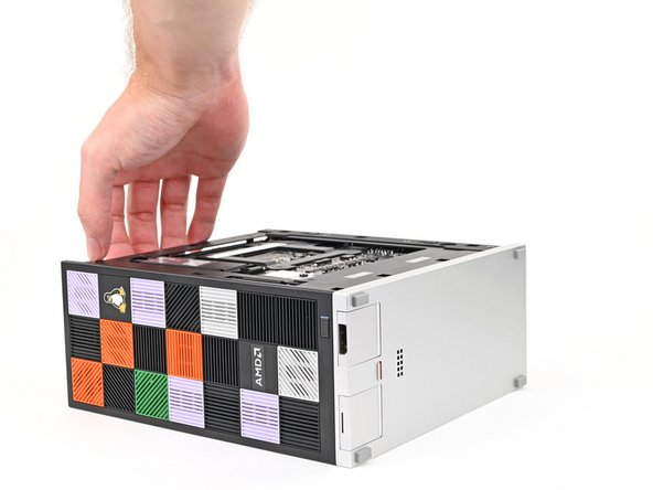
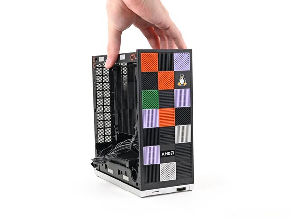
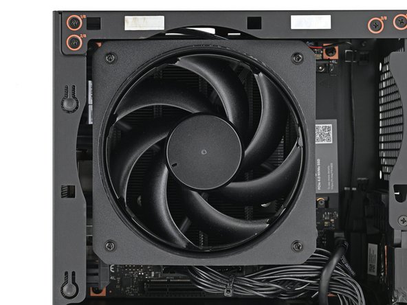
Lay down the Desktop on its side so the fan is facing upward.
-
-
-
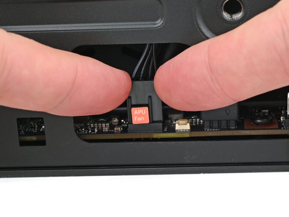
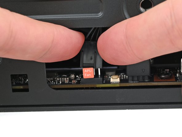
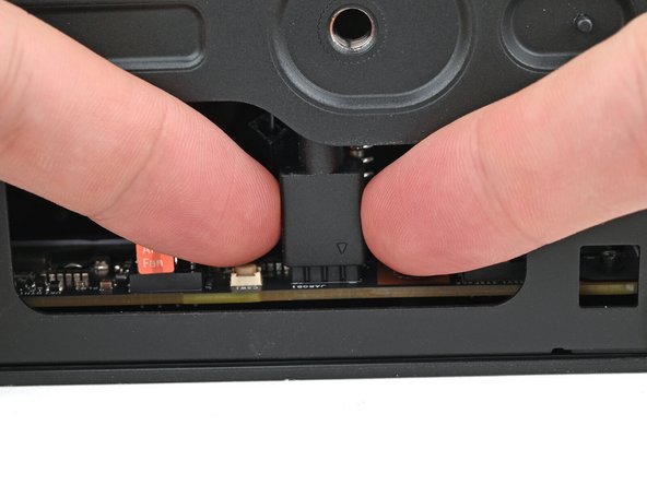
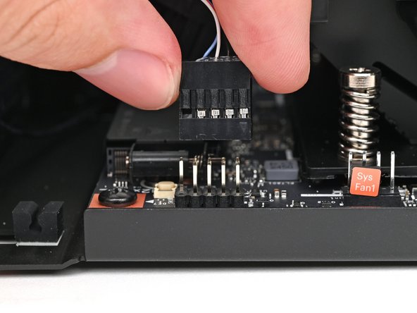
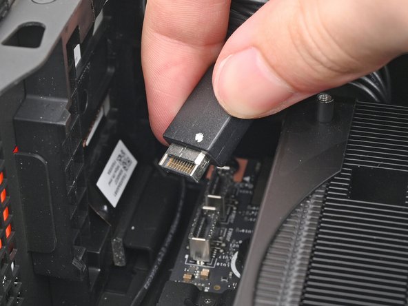
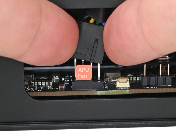
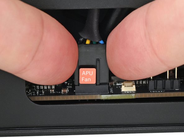
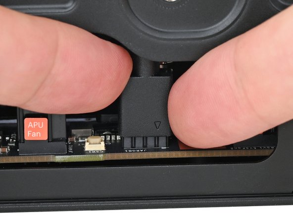
Use your fingers to lift the APU fan cable connector off its four‑pronged socket on the Mainboard.
-
-
-
If you aren't using an RGB fan, then skip this step.
-
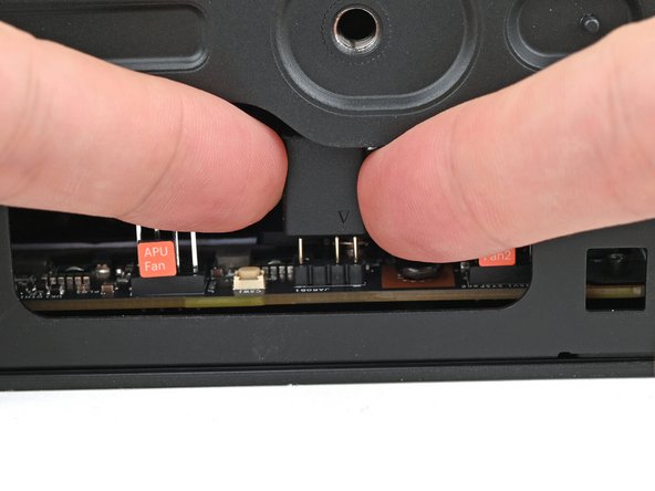
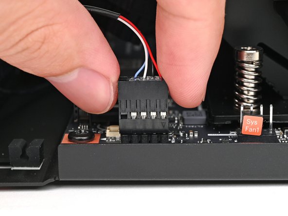
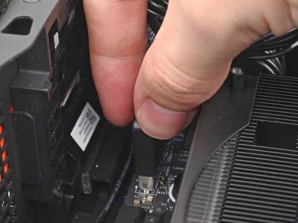
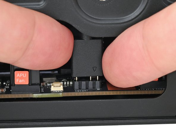
Use your fingers to lift the fan RGB cable connector off its three‑pronged socket on the Mainboard.
-
-
-
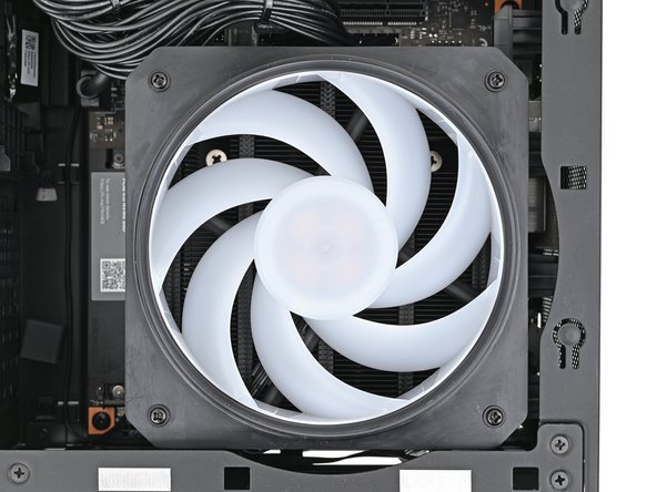
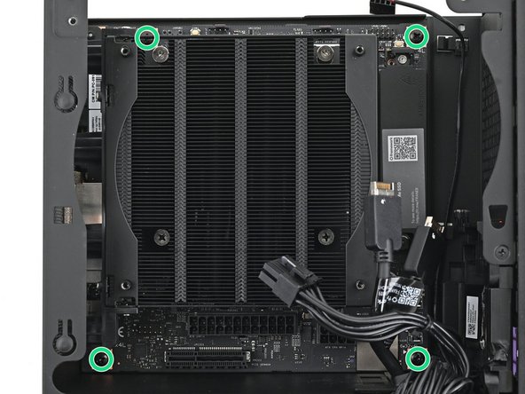
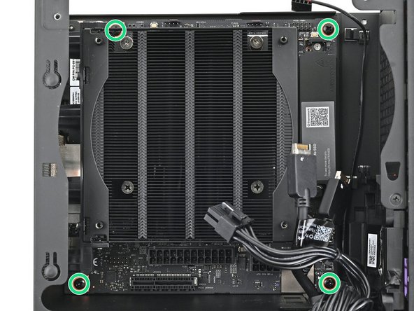
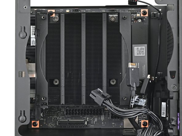
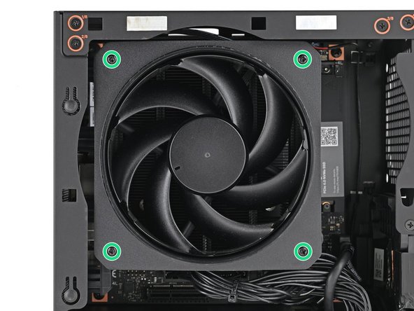
Use your Framework Desktop Screwdriver to remove the four 27.3 mm‑long Phillips screws securing the CPU fan and fan duct.
-
-
-
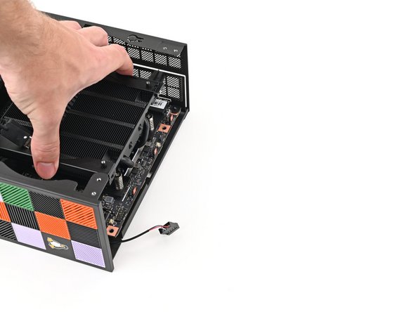
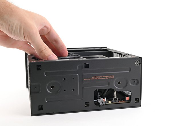
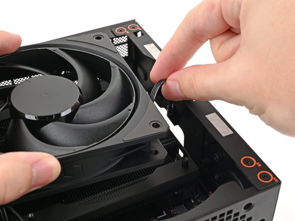
Lift the fan duct off the fan and remove it.
-
-
-
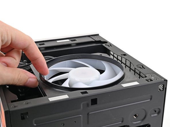
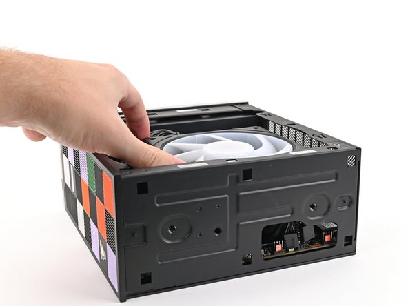
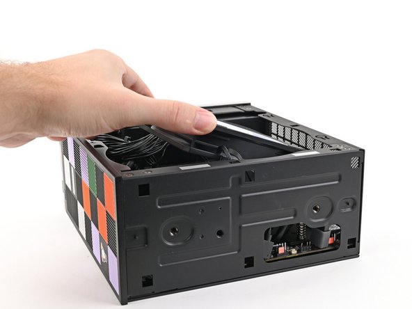
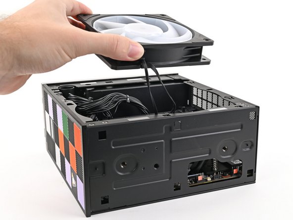
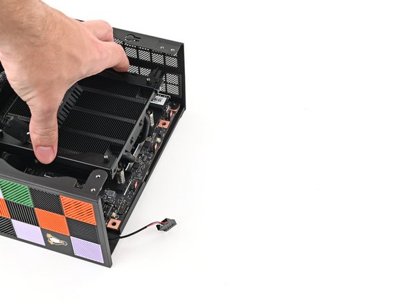
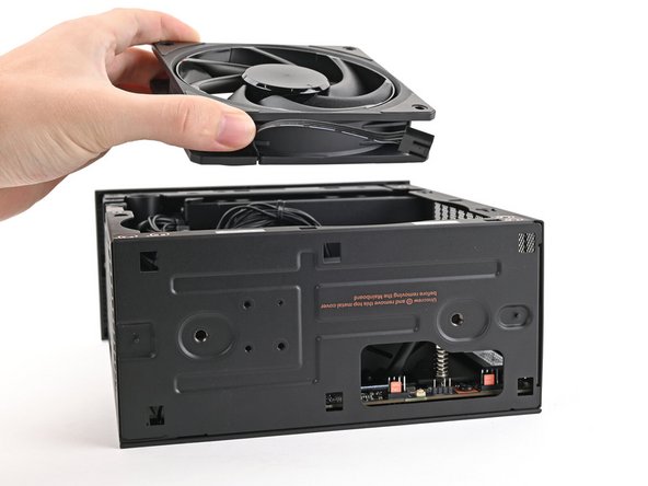
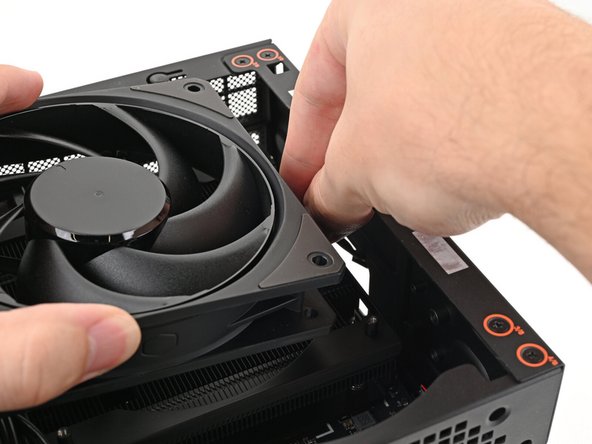
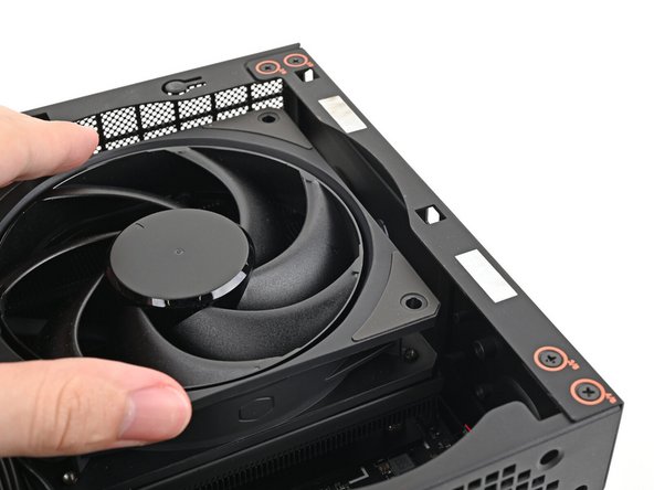
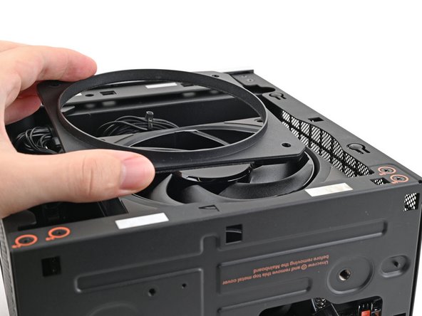
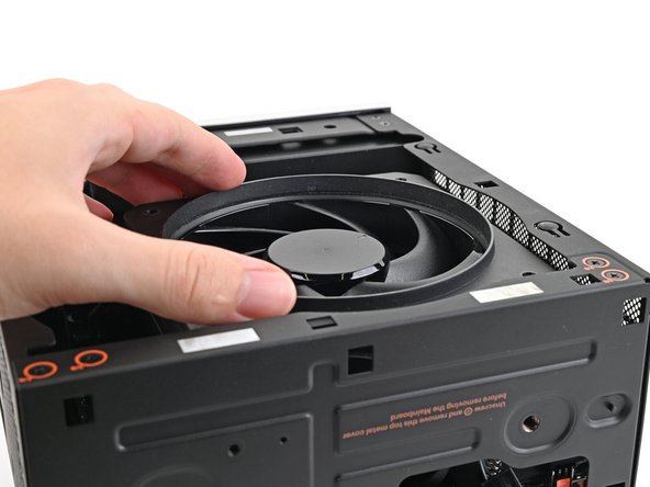
Lift the fan out of the chassis, making sure the cables thread through the side of the heatsink.
-
-
-
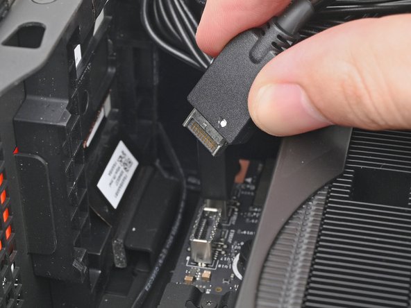
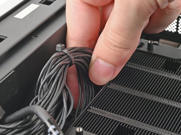
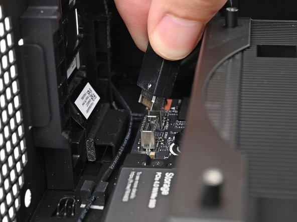
Pull the top Expansion Card connector straight out of its socket in the Mainboard to disconnect it.
-
-
-
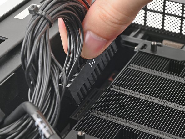
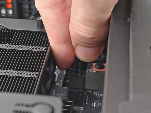
While squeezing the clip on the main power cable, pull it straight up and out of its socket to disconnect it.
-
-
-
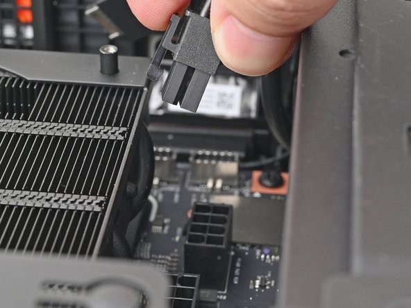
While squeezing the clip on the CPU power cable, pull it straight up and out of its socket to disconnect it.
-
-
-
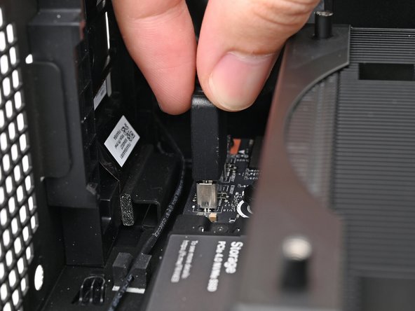
Pull the bottom Expansion Card connector straight out of its socket in the Mainboard to disconnect it.
-
-
-
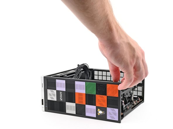
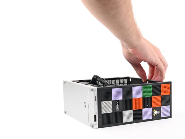
Lift the Desktop so it stands upright on your work surface.
-
-
-
Use your fingers to grip the top of the Right Panel and slide it upward to release its clips.
-
Remove the Right Panel.
-
-
-
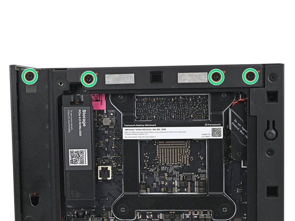
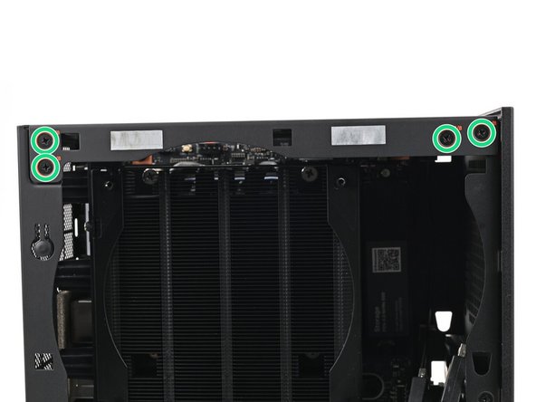
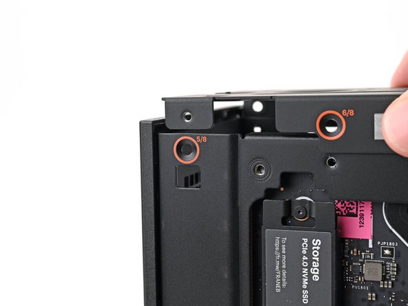
While holding the Desktop steady, use your Framework Desktop Screwdriver to remove the eight 4.0 mm‑long Phillips screws securing the top plate.
-
-
-
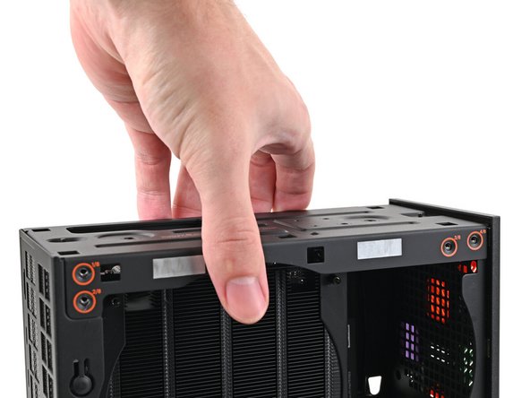
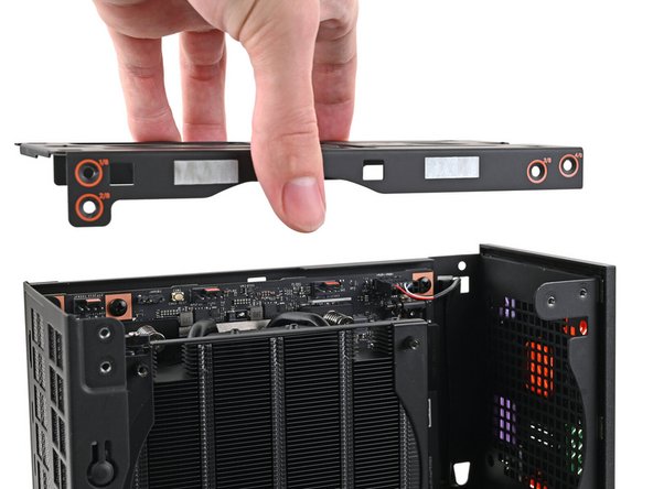
Lift the top plate off the Desktop and remove it.
-
-
-
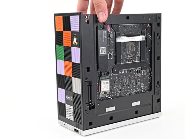
Lay the left side of the Desktop on your work surface so the underside of the Mainboard is facing upward.
-
-
-
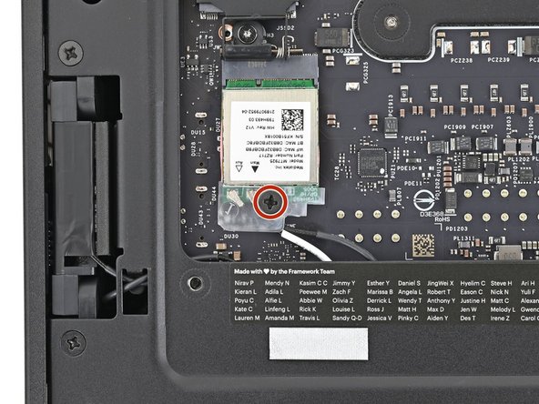
Use your Framework Desktop Screwdriver to remove the 7.0 mm‑long Phillips screw securing the Wi-Fi module.
-
-
-
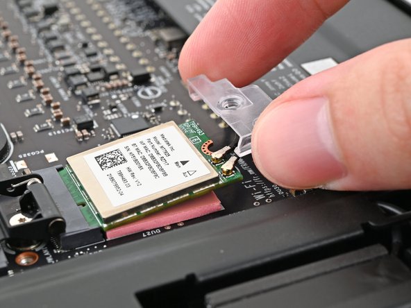
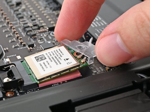
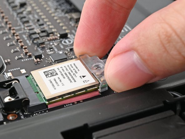
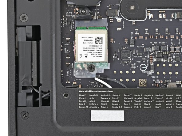
Use your fingers to slide the Wi-Fi module cover straight off the bottom of the module.
-
Remove the cover.
-
-
-
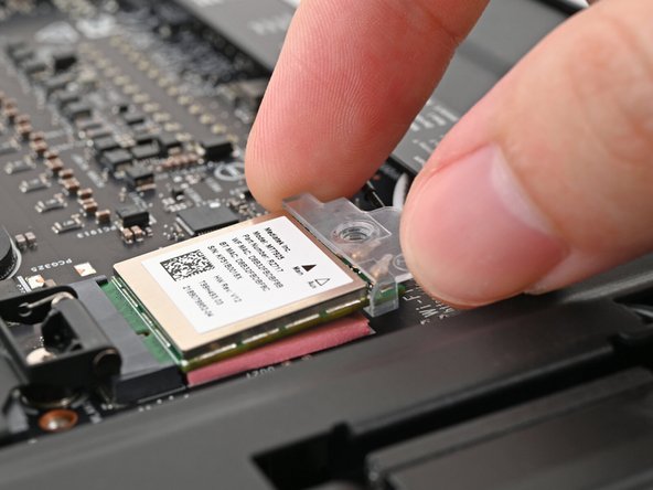
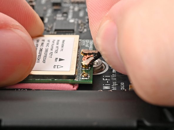
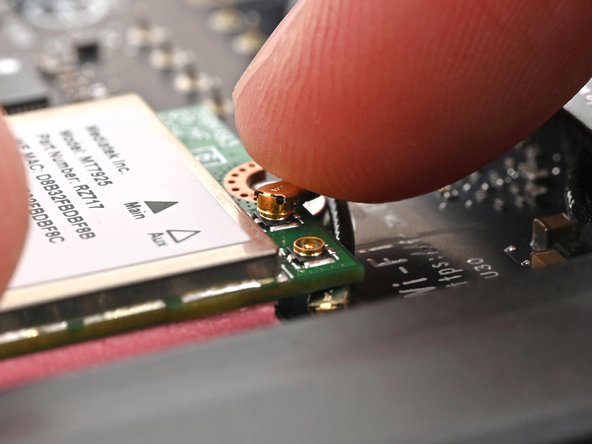
The Wi-Fi module has two delicate coaxial cable connectors. Follow this step carefully to avoid damaging them.
-
Press and hold the Wi-Fi module down with your fingers.
-
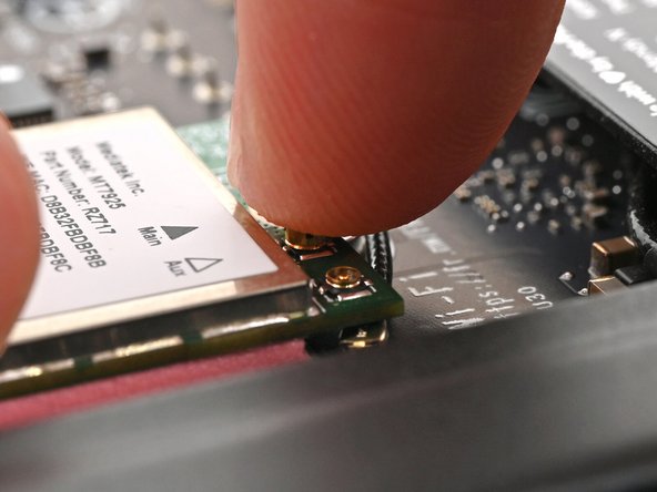
Use your fingers to grip the white antenna cable, as close to the metal head as possible.
-
If you have angled tweezers, slide one arm of a pair of tweezers under the antenna connector, as close to the metal head as possible.
-
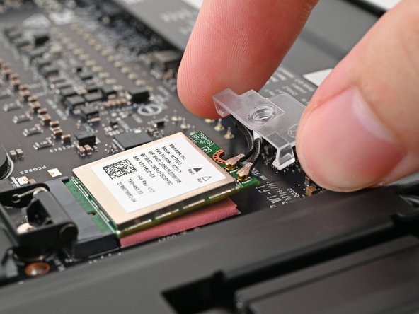
Gently lift the connector straight up to disconnect the white antenna cable.
-
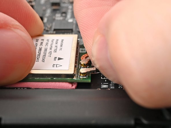
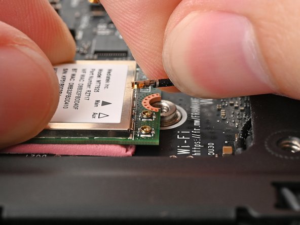
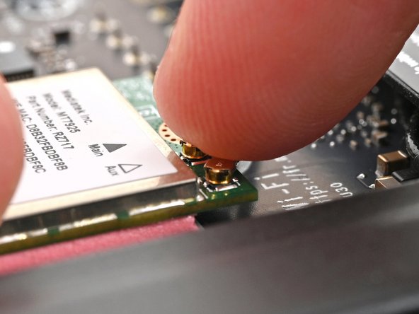
Repeat the procedure with the black antenna cable.
-
-
-
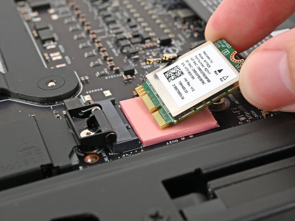
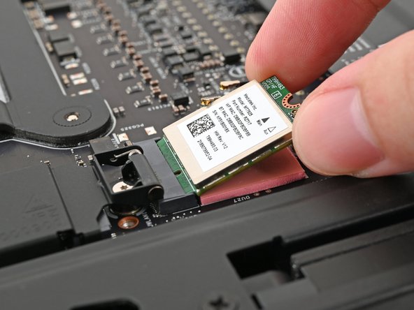
Grip the Wi-Fi module by its edges and pull it straight out of its socket.
-
Remove the Wi-Fi module.
-
-
-
Rotate the Desktop onto its right side so the Mainboard is facing upward.
-
-
-
Use your fingers to lift the power button cable connector off its nine‑pronged socket on the Mainboard.
-
-
-
Use your Framework Desktop Screwdriver to remove the four 8.2 mm‑long Phillips screws securing the Mainboard.
-
-
-
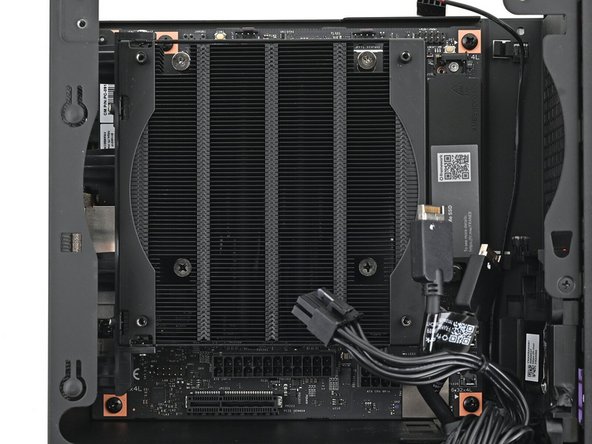
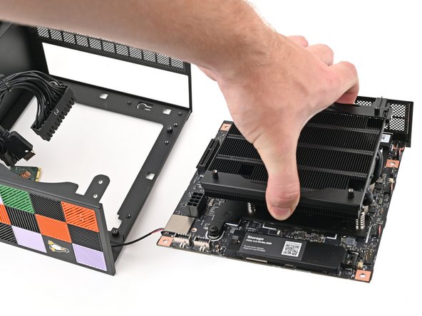
Grab the Mainboard by its heatsink and pull it towards the front of the Desktop to slide it out of the rear port cutout.
-
When handling the Heatsink, grab from the left and right sides (sides facing Front Panel & Back IO) as shown in the image to prevent bent fins and possible damage to the Heatsink.
-
Slide the Mainboard towards the top of the Desktop to remove it from the chassis.
-
-
-
Pull the power button cable out of its rubber clips on the chassis.
-
-
-
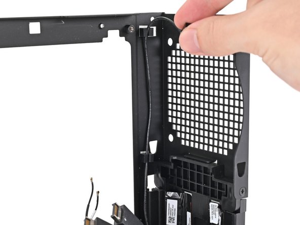
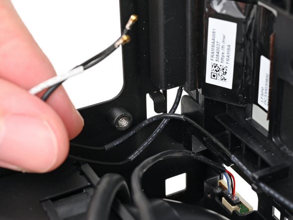
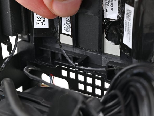
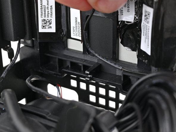
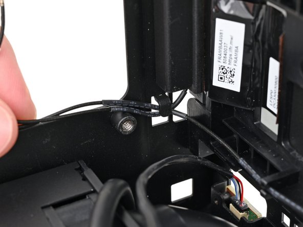
Push the antenna cables out of the metal hook in the chassis.
-
-
-
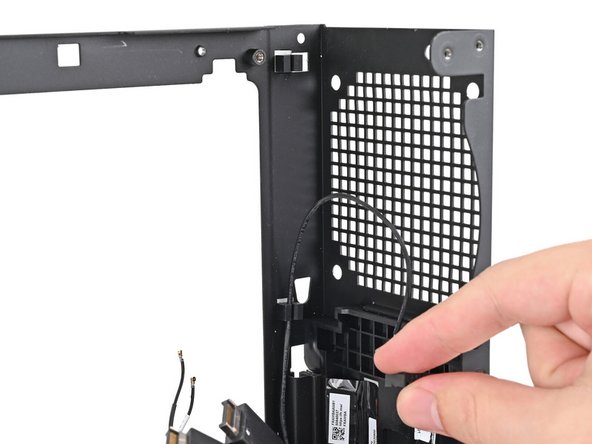
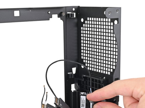
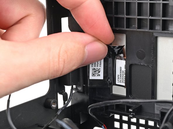
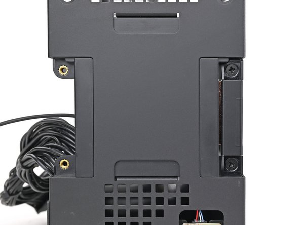
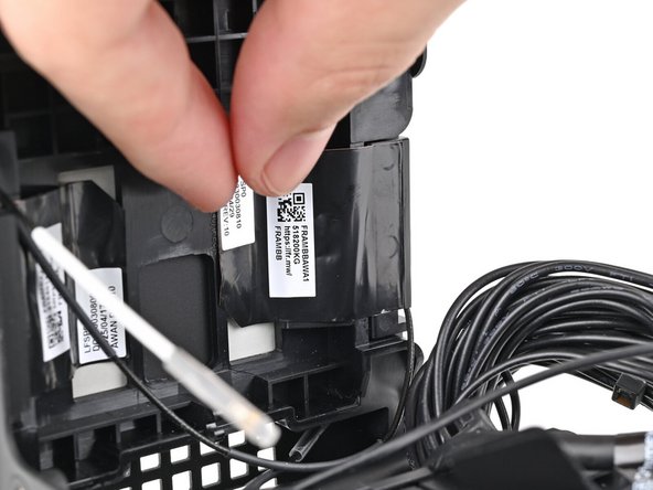
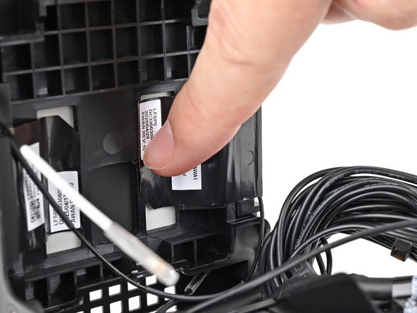
Pull the black antenna cable out of the plastic clip in the chassis.
-
-
-
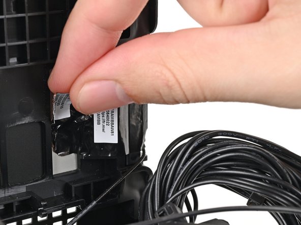
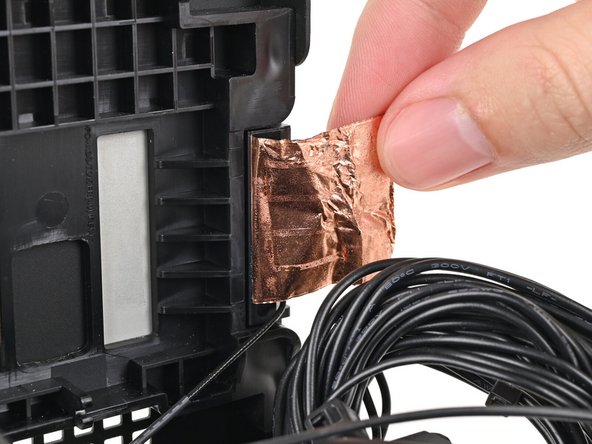
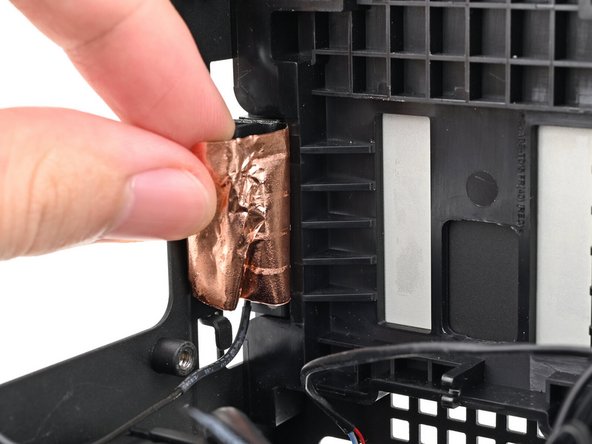
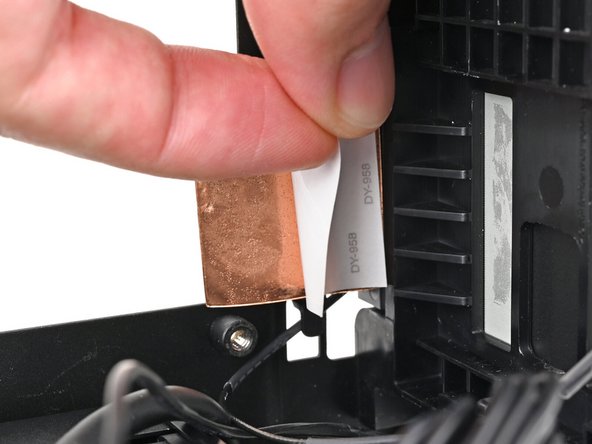
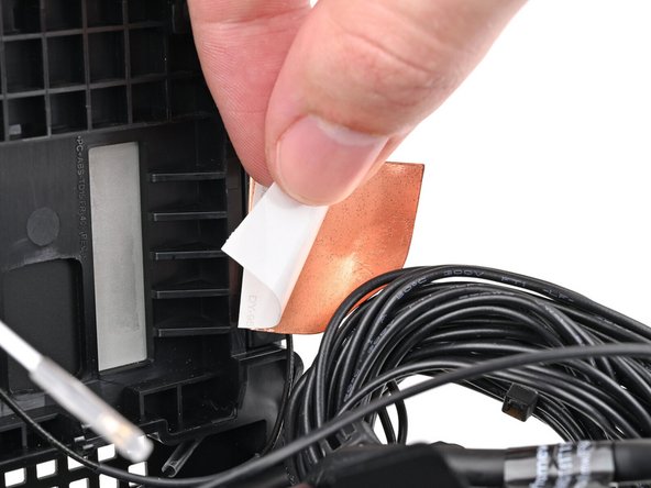
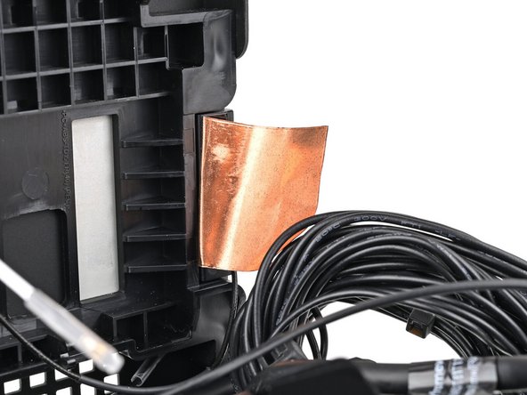
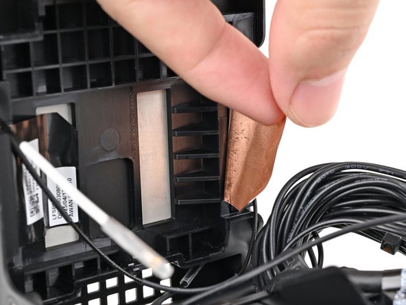
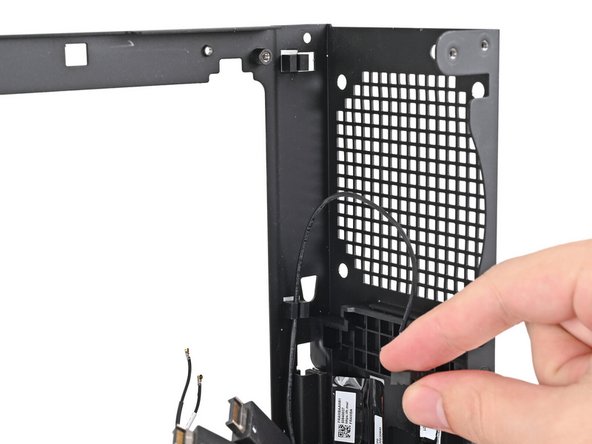
Use your fingers to peel the left antenna's copper film off the chassis.
-
-
-
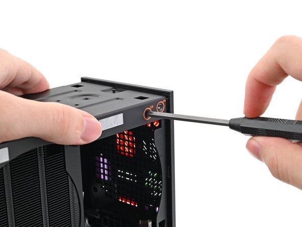
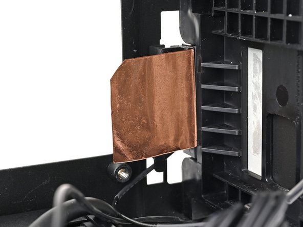
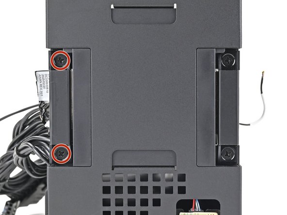
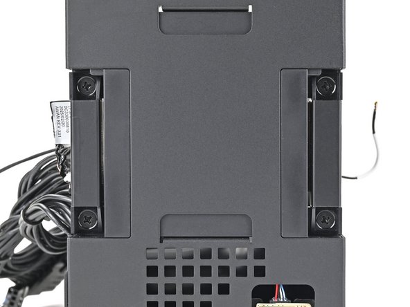
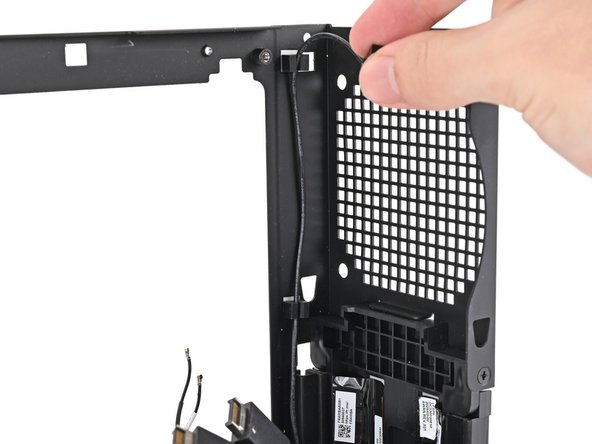
Use your Framework Desktop Screwdriver to remove the two 4.0 mm‑long Phillips screws securing the left antenna.
-
-
-
Lift the left antenna out of the chassis and remove it.
-
-
-
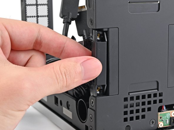
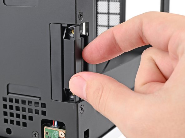
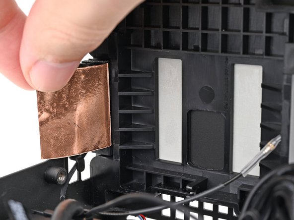
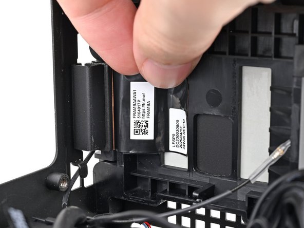
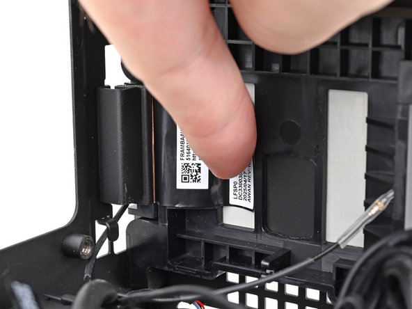
Use your fingers to peel the right antenna's copper film off the chassis.
-
-
-
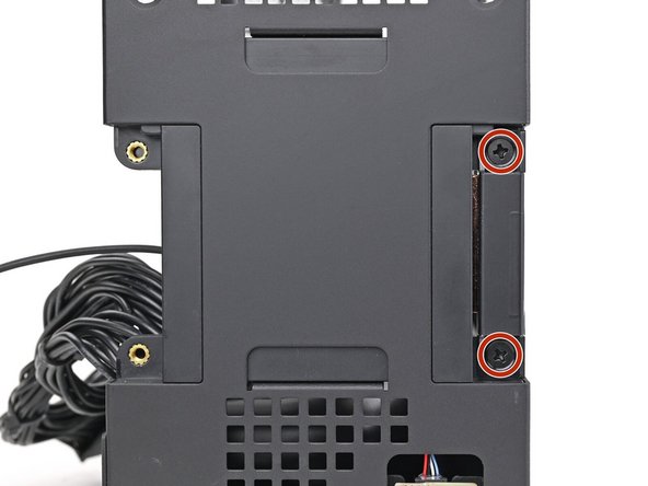
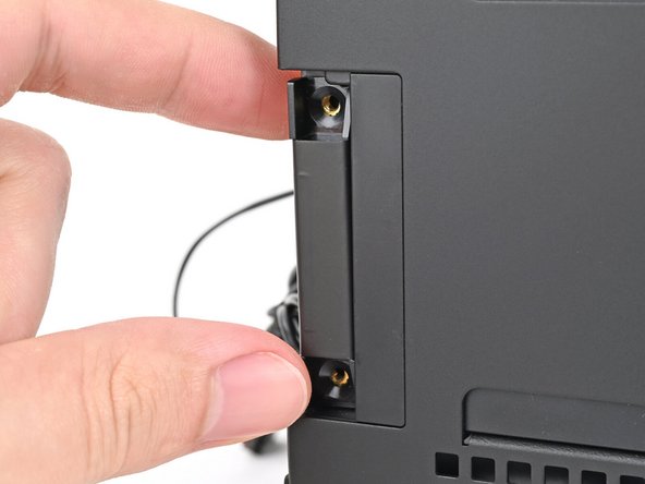
Use your Framework Desktop Screwdriver to remove the two 4.0 mm‑long Phillips screws securing the right antenna.
-
-
-
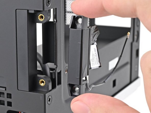
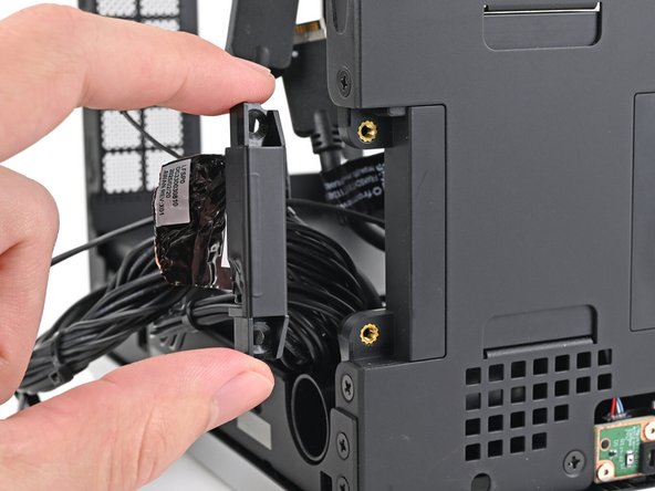
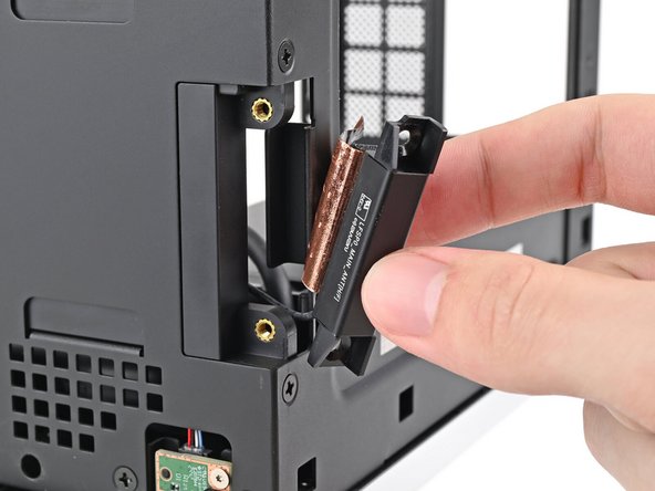
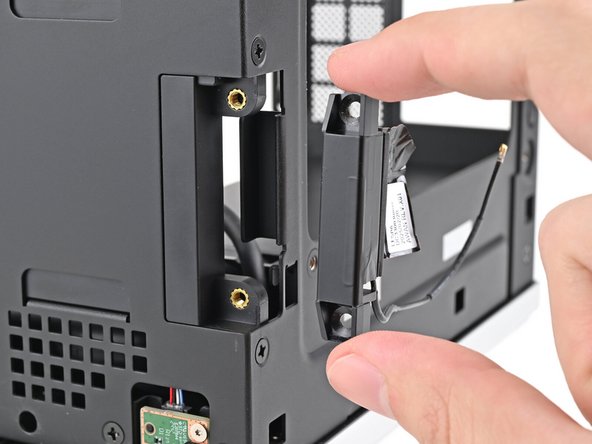
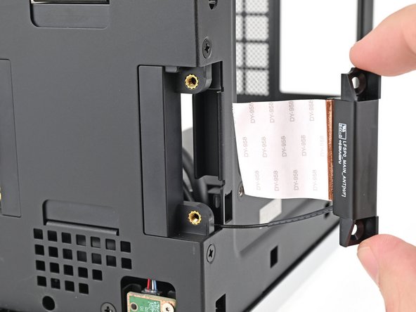
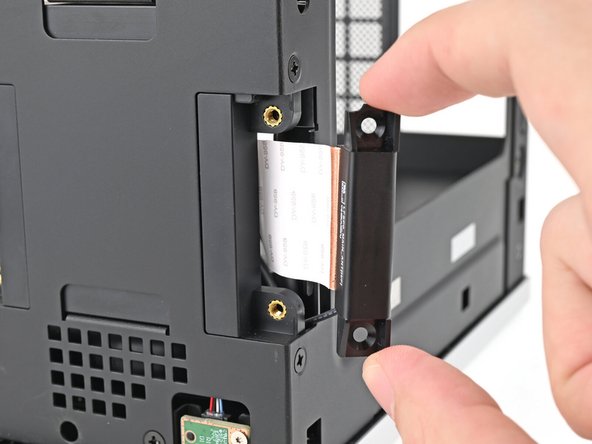
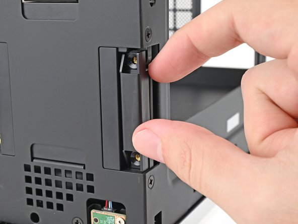
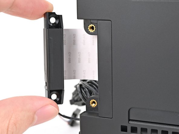
Lift the right antenna out of the chassis, making sure to thread the cable through the slot.
-
Remove the antenna.
-
-
-
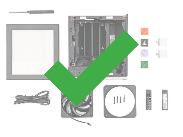
Congratulations on completing disassembly! The remaining steps will show how to reassemble your Framework Desktop.
-
-
-
The replacement antennas look similar. The right antenna has a short, black antenna cable.
-
Place the replacement right antenna into its slot on the chassis, making sure to thread the cable through the slot.
-
-
-
Use your Framework Desktop Screwdriver to install the two 4.0 mm‑long Phillips screws securing the right antenna.
-
-
-
Remove the liner from the back of your replacement right antenna.
-
-
-
Press the right antenna's copper film onto the chassis and adhere it.
-
-
-
The left antenna has a long, black antenna cable with a white tip.
-
Place the replacement left antenna into its slot on the chassis.
-
-
-
Use your Framework Desktop Screwdriver to install the two 4.0 mm‑long Phillips screws securing the left antenna.
-
-
-
Remove the liner from the back of your replacement left antenna.
-
-
-
Press the left antenna's copper film onto the chassis and adhere it.
-
-
-
Press the black antenna cable into the plastic clip in the chassis.
-
-
-
Pull the antenna cables into their metal hook in the chassis.
-
-
-
Push the power button cable into its rubber clips on the chassis.
-
-
-
Grab the Mainboard by its heatsink and slide it into the chassis.
-
When handling the Heatsink, grab from the left and right sides (sides facing Front Panel & Back IO) as shown in the image to prevent bent fins and possible damage to the Heatsink.
-
Align the rear ports with its cutout and the screw posts with the screw holes on the Mainboard.
-
You'll feel the Mainboard rest onto the screw posts when it's aligned properly.
-
Make sure no cables are trapped underneath the Mainboard before continuing.
-
-
-
Use your Framework Desktop Screwdriver to install the four 8.2 mm‑long Phillips screws securing the Mainboard.
-
-
-
Slide the power button cable over the nine-pronged connector on the Mainboard.
-
-
-
Rotate the Desktop onto its left side so the underside of the Mainboard is facing upward.
-
-
-
Hold the Wi-Fi module by its edges. Don't touch the gold contacts with your fingers. If you do, wipe the contacts with a clean, lint-free cloth to remove any finger oils.
-
Align the Wi-Fi module's gold contacts and notch with the socket on the Mainboard.
-
Insert the Wi-Fi module into the socket at a shallow angle. The gold contacts should mostly be covered by the socket.
-
The Wi-Fi module fits into the socket in one orientation. If it doesn't fit, try flipping the module.
-
-
-
Hold the Wi-Fi module down with your fingers.
-
Position the black antenna cable connector over the left Wi-Fi module's coaxial socket.
-
Tweezers can help position the connector.
-
Use your finger to press the connector into place. You should feel a faint click, and the cable will stay attached to the socket by itself.
-
These connectors are very delicate! If the connector doesn't feel like it's clicking in place, reposition the connector and try again.
-
Repeat the procedure with the white antenna cable.
-
-
-
Hook the Wi-Fi bracket over the corner of the Wi-Fi module opposite the antenna cables.
-
Rotate the bracket over the Wi-Fi module, making sure the screw hole isn't being obstructed by the antenna cables.
-
-
-
Use your Framework Desktop Screwdriver to install the 7.0 mm‑long Phillips screw securing the Wi-Fi module.
-
-
-
Rotate the Desktop so it sits upright on your work surface.
-
-
-
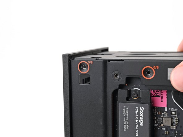
Place the top plate on top of the Desktop, making sure it slots into the chassis so the orange circles are visible.
-
-
-
Make sure the matching screw hole on the top plate labeled "5/8" is slotted on the inside of the Chassis so that the orange circle is visible.
-
-
-
While holding the Desktop steady, use your Framework Desktop Screwdriver to install the eight 4.0 mm‑long Phillips screws securing the top plate.
-
-
-
Slide the Right Panel onto the right edge of the chassis, from top to bottom, and press it flat to ensure its clips are slotted into place.
-
There should be a small gap between the bottom of the Right Panel and the silver base.
-
Push the Right Panel towards the base of the computer to engage the clips.
-
-
-
Lay the right side of the Desktop on your work surface so the Mainboard is facing upward.
-
-
-
Slide the bottom Expansion Card cable into its socket on the Mainboard.
-
-
-
Orient the CPU power supply cable so its clip is facing the heatsink.
-
Slide the cable into its socket on the Mainboard until you feel it click into place.
-
-
-
Orient the main power supply cable so its clip is facing away from the heatsink.
-
Slide the cable into its socket on the Mainboard until you feel it click into place.
-
-
-
Slide the top Expansion Card cable into its socket on the Mainboard.
-
-
-
Orient the fan so its label is facing downward and the cable(s) is pointing towards the top of the computer.
-
If your fan has an arrow indicating airflow direction, make sure it's pointed towards the heatsink.
-
If you're using a different fan, orient it such that the fan is blowing towards the heatsink, not away.
-
Lay the fan on top of the heatsink, making sure the cables are routed so they poke out of the hole on the top of the computer.
-
-
-
If the cables aren't routed properly, lift the fan up slightly and use your fingers to reposition the cables over the side of the heatsink.
-
If you're installing an RGB fan, make sure the "male" end of the RGB cable is covered and set aside in the corner of the chassis.
-
-
-
Lay the fan duct on top of the fan with the lip facing upward.
-
Align the screw holes on the fan duct with the ones on the fan.
-
-
-
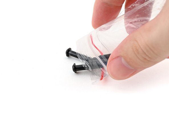
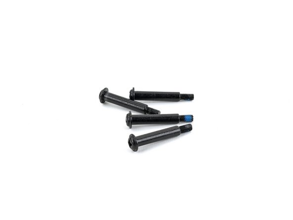
(if new) Remove the fan screws from their packaging and make sure there are four screws total.
-
-
-
Use your Framework Desktop Screwdriver to install the four 27.3 mm‑long Phillips screws securing the CPU fan and fan duct.
-
-
-
Orient the main fan cable so its two vertical lines are facing you.
-
Slide the main fan cable over the four-pronged connector labeled "APU Fan," making sure the orange label slots between the vertical lines.
-
-
-
If you aren't using an RGB fan, then skip this step.
-
Orient the RGB cable so the arrow is facing you.
-
Use your fingers to slide the RGB cable over the three pronged connector located to the right of the "APU Fan" connector.
-
-
-
Slide the Left Panel onto the left edge of the chassis and press it flat to ensure its clips are slotted into place.
-
There should be a small gap between the bottom of the Left Panel and the silver base.
-
Push the Left Panel towards the base of the computer to close the gap and engage the clips.
-
-
-
Orient the Top Panel so its arrow is pointing towards the rear of the computer.
-
While holding the Top Panel at a slight downward angle, slide it across the top of the chassis (from rear to front) until you feel its clips catch.
-
There should be a small gap between the Top Panel and the front of the Desktop.
-
Lay the Top Panel flat on the chassis to align the remaining clips.
-
-
-
While securing the computer with one hand, use the other hand to slide the Top Panel towards the front of the computer to close the gap and engage the clips.
-
-
-
If you're installing the Handle on your Desktop, follow this step. Otherwise, skip it.
-
Place the Handle over the Top Panel screw holes.
-
While holding the Handle in place, twist the screw threads on both sides clockwise until they're snug on the Top Panel.
-
-
-
Insert the top panel screw into its hole and twist clockwise until it feels snug.
-
-
-
Repeat the same procedure for the other top panel screw.
-
-
-
Use your finger to close the two D-rings on the top panel screws.
-


You finished fixing your Framework Desktop!
Take your e-waste to an R2 or e-Stewards certified recycler.
If you need help, contact Framework support.
You finished fixing your Framework Desktop!
Take your e-waste to an R2 or e-Stewards certified recycler.
If you need help, contact Framework support.