Introduction
Follow this guide to remove and replace the antennas in your Framework Laptop 12.
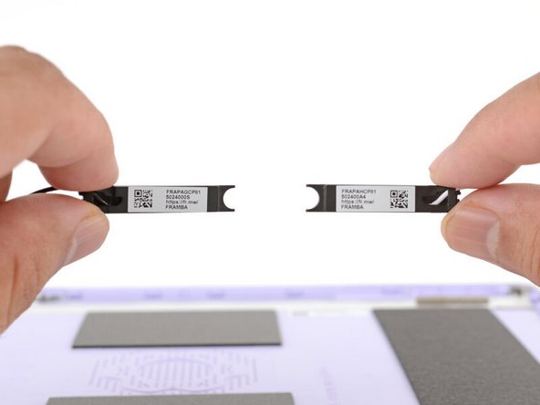
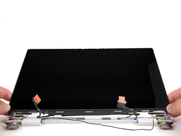
The Framework Laptop 12 has two antennas—one in each corner behind the top edge of the display. They connect to the wireless card via thin antenna cables, enabling both Wi-Fi and Bluetooth reception.
Removing the antennas is an extensive procedure. If you're having issues with Wi-Fi or Bluetooth reception, be sure to troubleshoot all other software and hardware possibilities before attempting this repair.
You'll encounter some component terms in this guide:
- The Input Cover is the part that contains the keyboard and trackpad.
- The Display Cover is the plastic bezel strip below the screen.
- The Top Cover is the plastic shell that houses the display.
- The Bottom Cover is the plastic shell that forms the bottom half of the laptop.
Tools
Parts
No parts specified.
-
-
Before you begin repairs, unplug your laptop and shut it down from the operating system. This ensures that the laptop isn't in standby/suspend mode.
-
The indicator LEDs along the edges should be unlit. The laptop should be silent.
-
If you accidentally turn on the laptop during repair, hold the power button down for 10 seconds to shut it down.
-
Make sure your Framework Screwdriver has the T5 Torx bit (labeled as T-5) facing outwards. If it's not, pull the bit out and flip it.
-
-
-
Set your Framework Laptop face-down on a clean work surface.
-
-
-
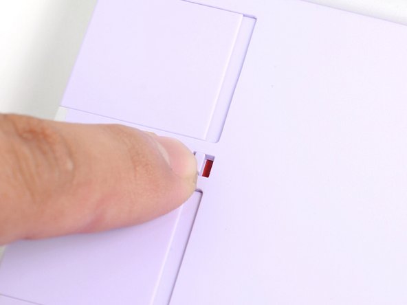
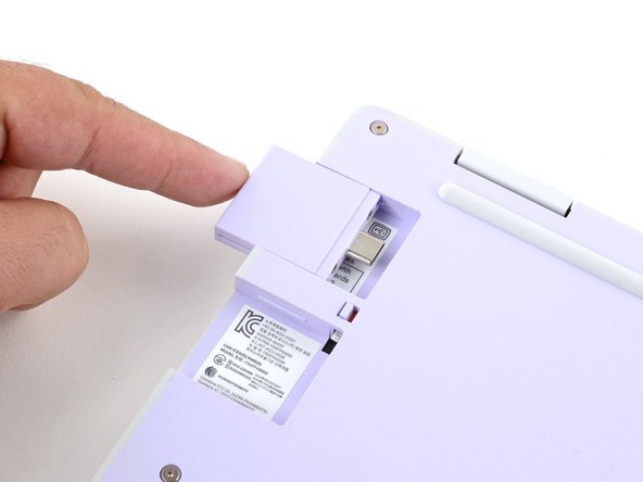
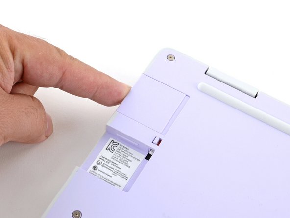
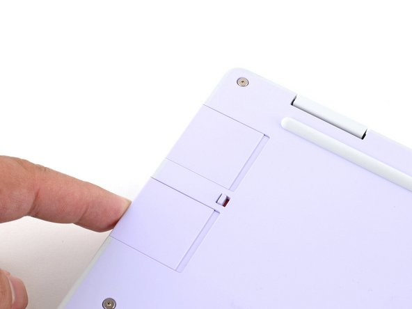
Use your fingers to flip the two Expansion Card latches (one for each side) into the unlocked position.
-
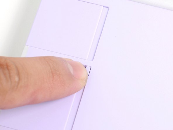
The latches display a red bar when they're unlocked.
-
-
-
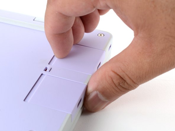
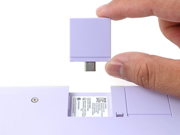
Grip the lip of an Expansion Card with your fingers.
-
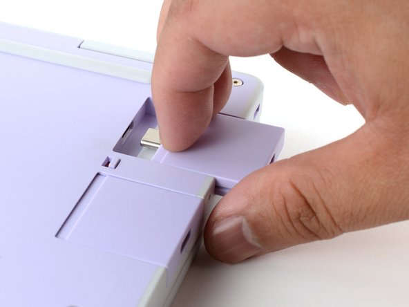
Pull the Expansion Card out of its slot and remove it.
-
If you have trouble pulling the Expansion Card out, you can also use the flat end of your Framework Screwdriver to push against the lip.
-
Repeat this procedure to remove all remaining Expansion Cards.
-
-
-
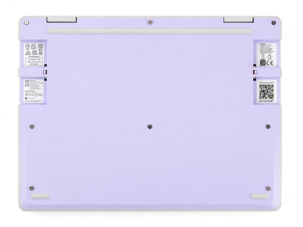
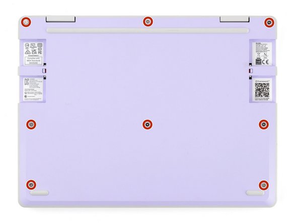
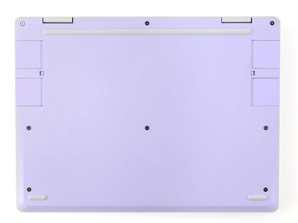
Use your Framework Screwdriver to fully loosen the eight captive T5 Torx screws on the bottom of your laptop.
-
Most screws in your Framework Laptop (including these) are captive—they're designed to stay in place after you loosen them.
-
Your laptop comes with a spare set of screws in the frame above the battery. Be careful—the replacement screws aren't captive.
-
-
-
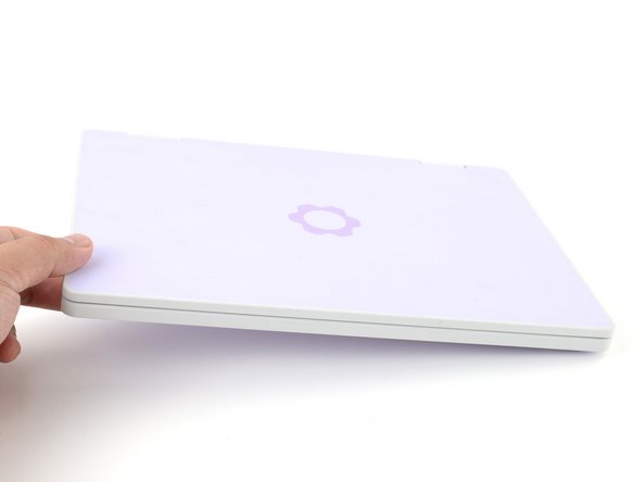
Flip your laptop face-up on your work surface.
-
-
-
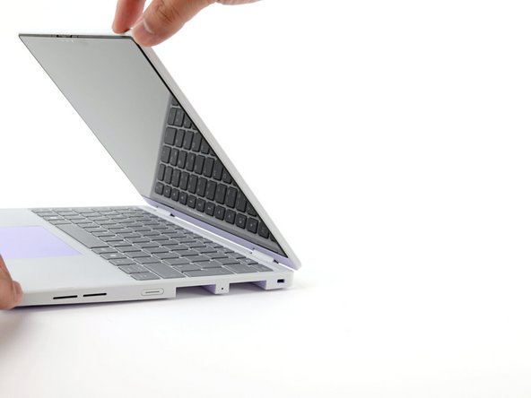
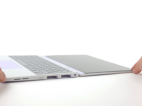
Open the laptop lid so that both the screen and the base lie flat on your work surface.
-
-
-
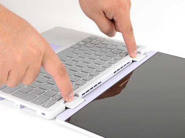
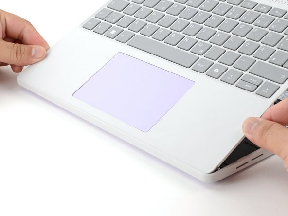
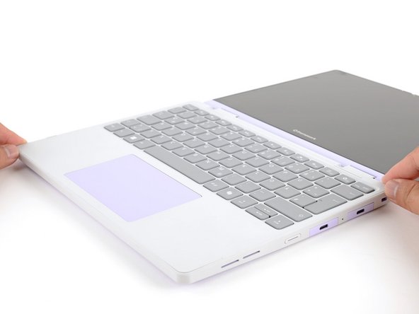
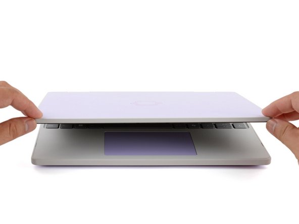
Use your fingers to grip the Input Cover in the hinge cutouts.
-
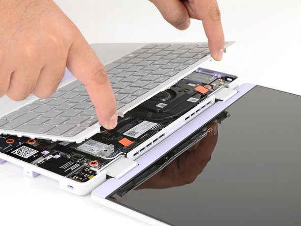
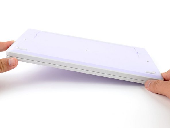
Lift upwards to swing the Input Cover up from the base of the laptop.
-
You may feel resistance from the magnets. If the cover feels like it's snagged, check that you've fully loosened the screws on the bottom of your laptop.
-
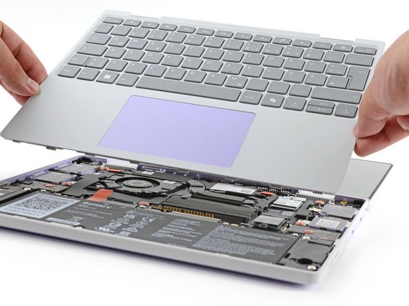
Remove the Input Cover.
-
-
-
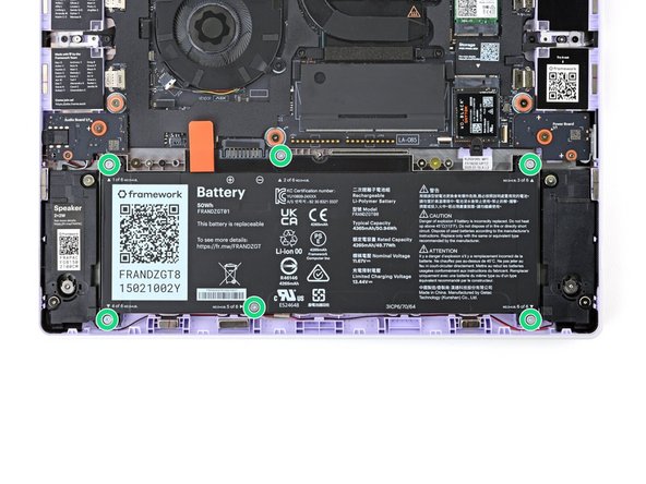
Use your Framework Screwdriver to loosen the six captive T5 Torx screws securing the battery.
-
-
-
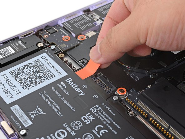
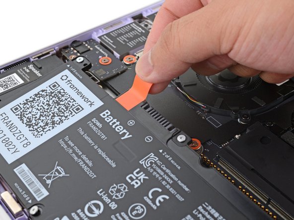
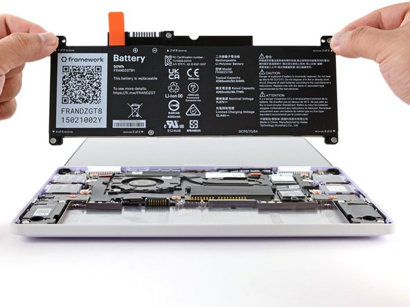
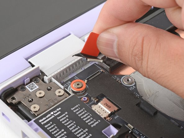
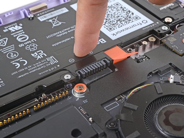
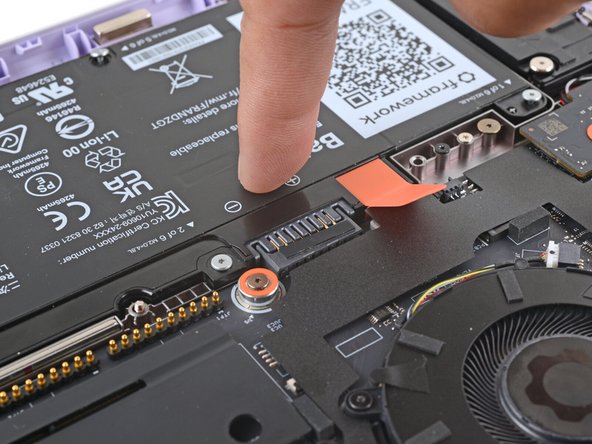
Grab the orange battery tab with your fingers and lift straight up to disconnect the battery.
-
The battery connector can be tight, requiring some force. If it feels like part of the battery won't come up, check that the battery screws are fully loosened.
-
-
-
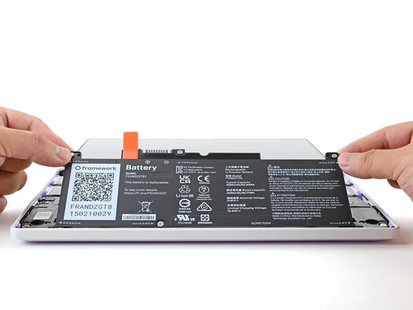
Lift and remove the battery from the laptop.
-
-
-
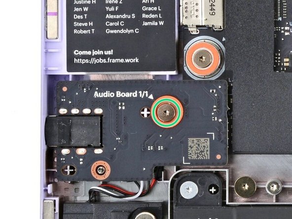
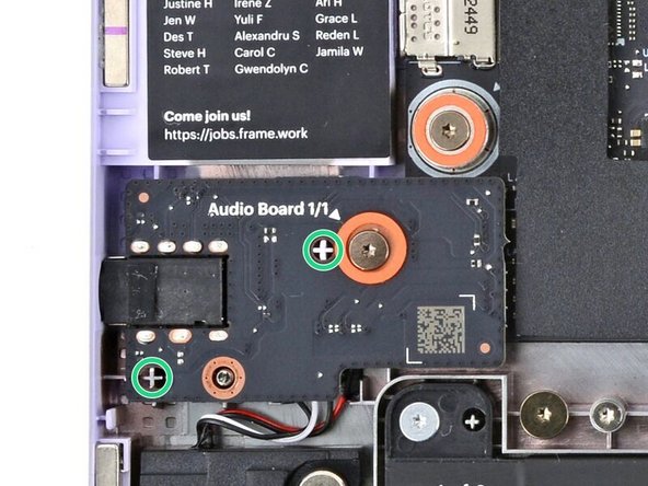
Use your Framework Screwdriver to loosen the captive T5 Torx screw securing the Audio Board along the left edge of the laptop.
-
-
-
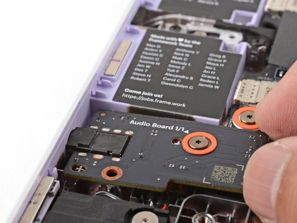
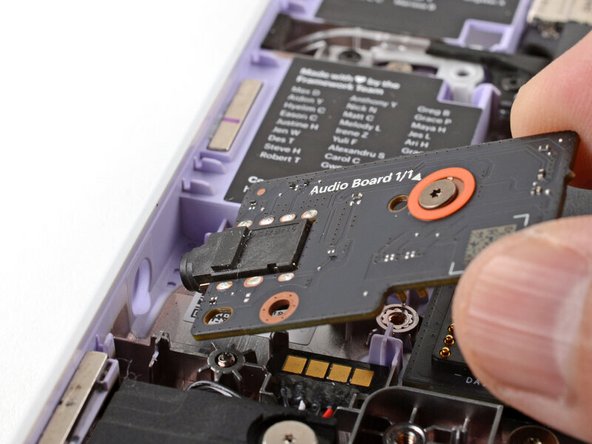
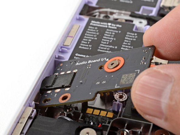
Use your fingers to lift the right edge of the Audio Board and pull it out of its recess.
-
Remove the Audio Board.
-
-
-
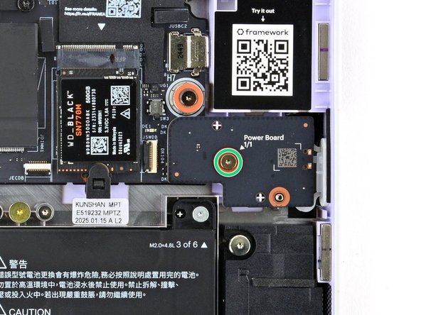
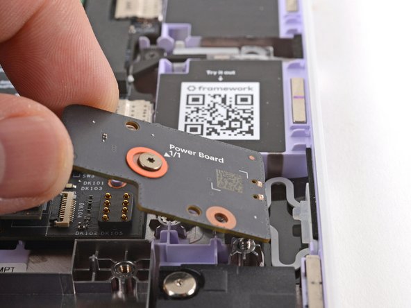
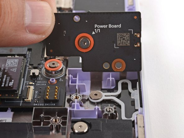
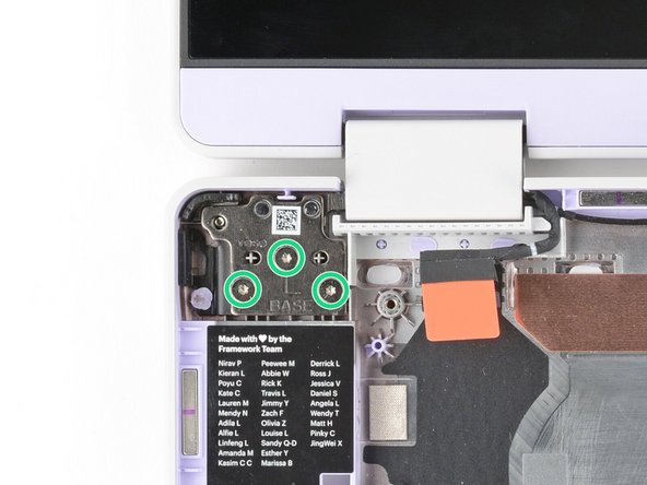
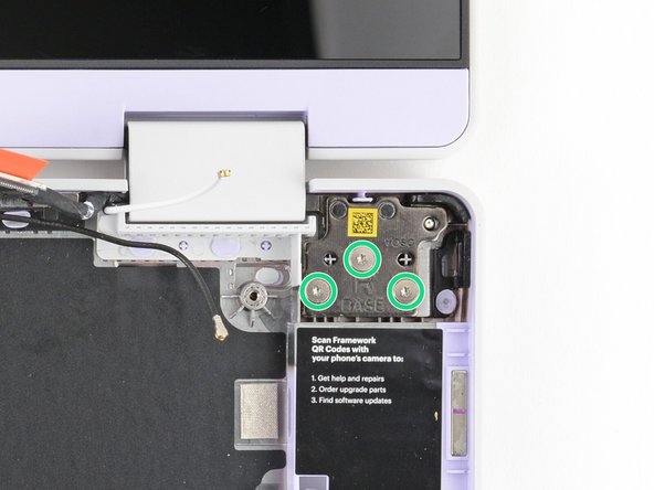
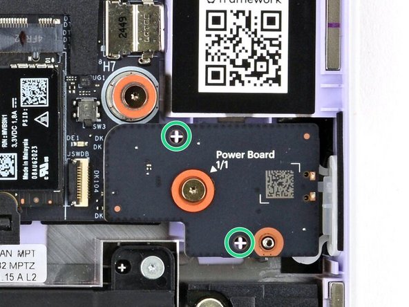
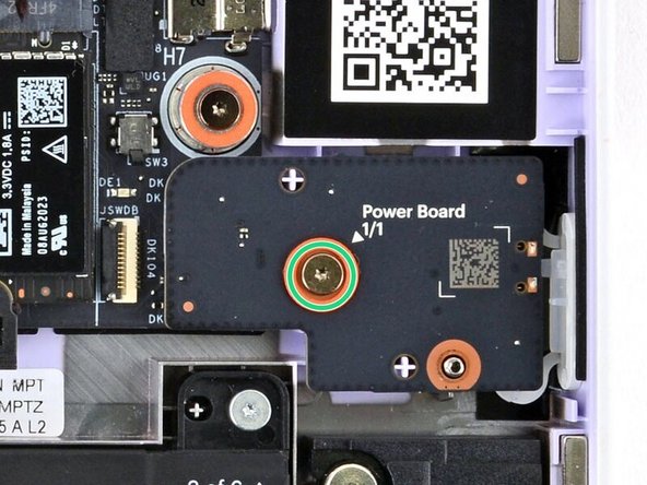
Use your Framework Screwdriver to loosen the captive T5 Torx screw securing the Power Button Board (labeled "Power Board").
-
-
-
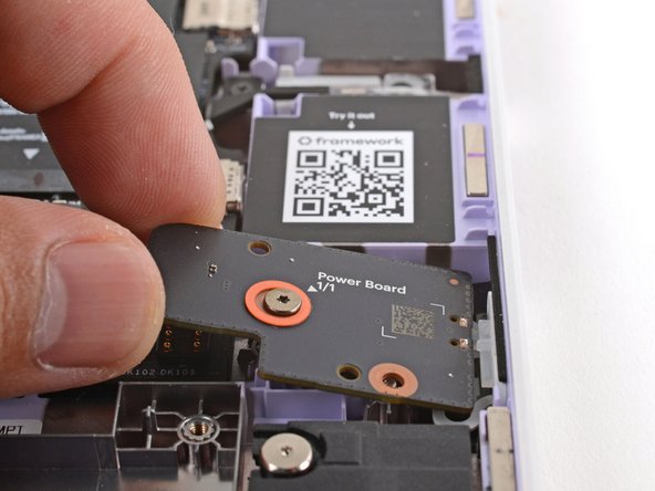
Use your fingers to lift and remove the Power Button Board.
-
-
-
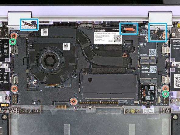
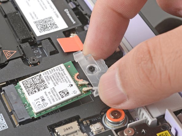
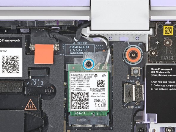
Use your Framework Screwdriver to loosen the captive T5 Torx screw securing the Wi-Fi card bracket.
-
The Wi-Fi card will pop up slightly when you unfasten the bracket.
-
-
-
Grab the Wi-Fi card bracket with your fingers and slide it off the top of the Wi-Fi card.
-
Remove the bracket and store it in a safe location for reassembly.
-
-
-
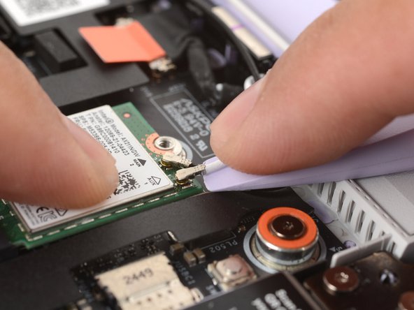
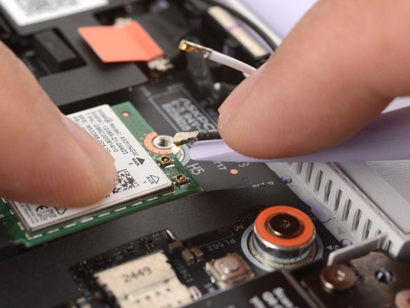
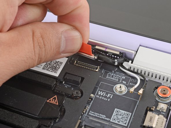
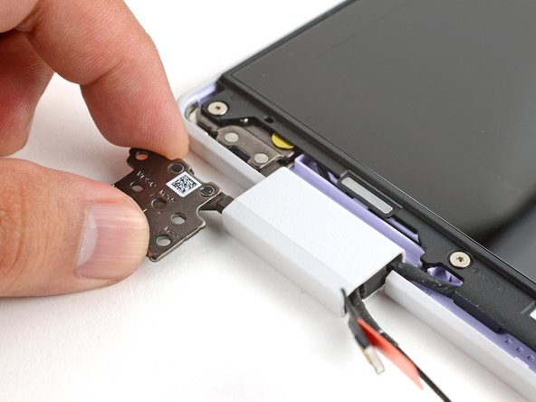
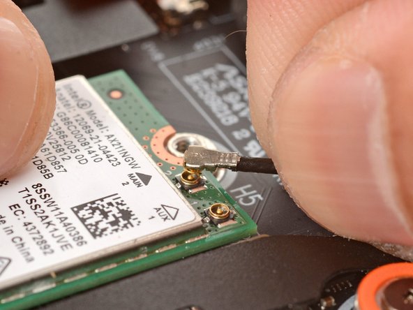
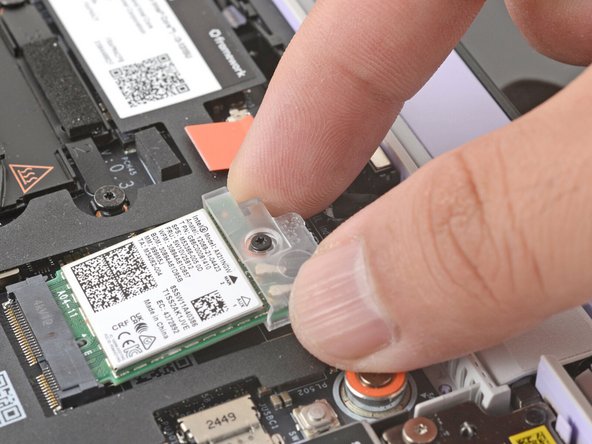
The Wi-Fi card has two delicate coaxial cable connectors. Follow this step carefully to avoid damaging them.
-
Press and hold the Wi-Fi card down with your finger.
-
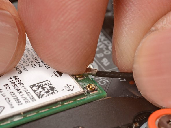
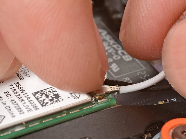
Slide the flat edge of your Framework Screwdriver under the white antenna cable, as close to the metal head as possible.
-
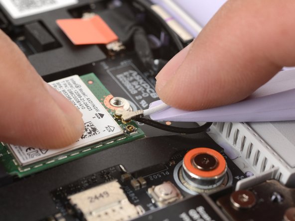
Gently lift the connector straight up to disconnect the white antenna cable.
-
Repeat the procedure with the black antenna cable.
-
-
-
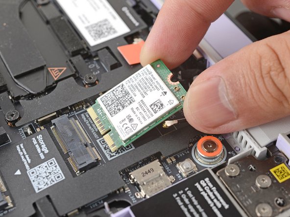
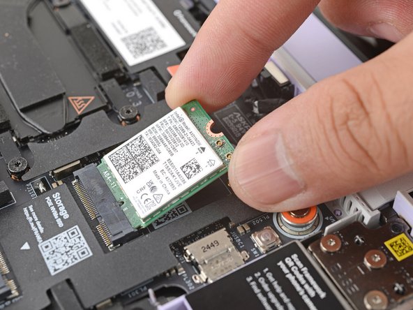
Grab the Wi-Fi card by the edges and pull it out of its socket.
-
Remove the Wi-Fi card.
-
-
-
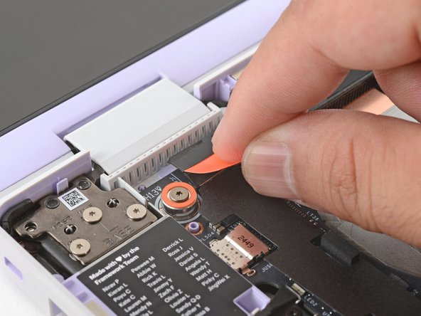
Use your fingers to grab the orange tab on the webcam cable, located near the left hinge.
-
Lift straight up to disconnect the cable.
-
-
-
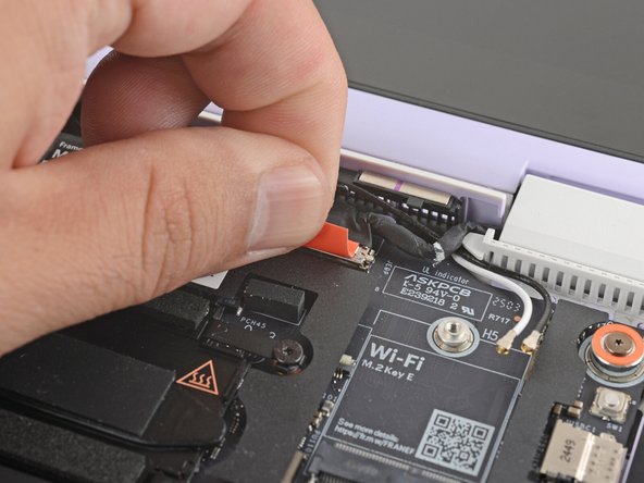
Use your fingers to grab the orange tab on the display cable, located near the right hinge.
-
Lift straight up to disconnect the cable.
-
-
-
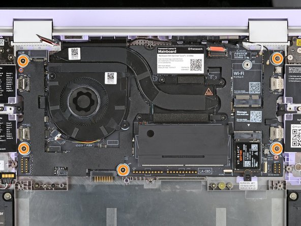
Use your Framework Screwdriver to loosen the five captive T5 Torx screws securing the Mainboard.
-
These screws are also physically marked with an orange ring on the Mainboard.
-
-
-
Make sure you've removed all Expansion Cards. Installed cards will hold the Mainboard in place.
-
Use your fingers to grab the Mainboard by its edges.
-
Lift and remove the Mainboard.
-
-
-
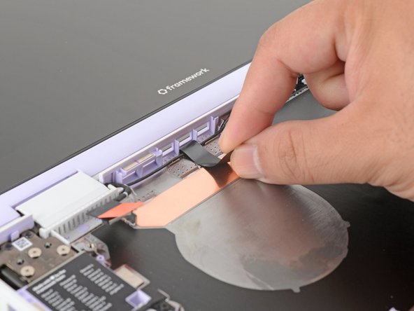
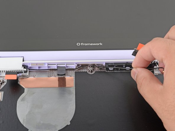
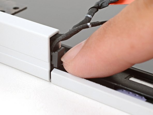
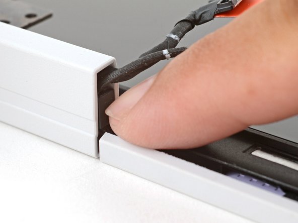
Use your fingers to lift the black plastic loop securing the antenna cable, near the heat vents by the left hinge.
-
-
-
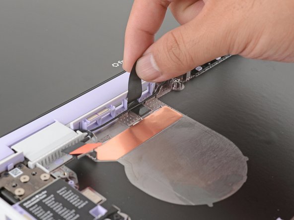
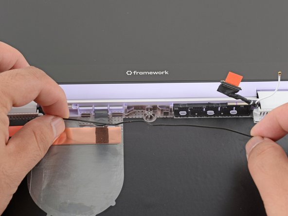
Use your fingers to lift and guide the antenna cable out of the frame channel.
-
-
-
Use your fingers to gently lift the webcam cable out of its plastic channel.
-
-
-
Use your Framework Screwdriver to remove the six (three per hinge) 4.5 mm‑long T5 Torx screws securing the two hinges.
-
These screws are not captive. Store them in a safe location for reassembly.
-
-
-
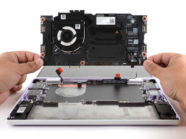
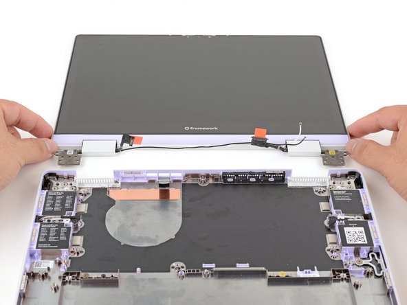
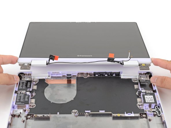
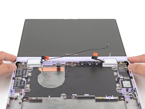
Use your fingers to lift the hinges over the Bottom Cover lip.
-
Separate the Top Cover from the Bottom Cover.
-
-
-
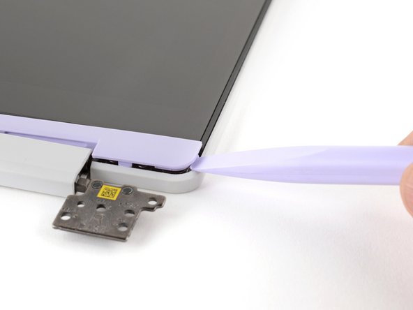
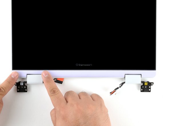
The Display Cover is held in place with magnets along its top edge and clips along its remaining edges.
-
Use the flat end of your Framework Screwdriver to pry up the right edge of the Display Cover.
-
-
-
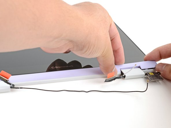
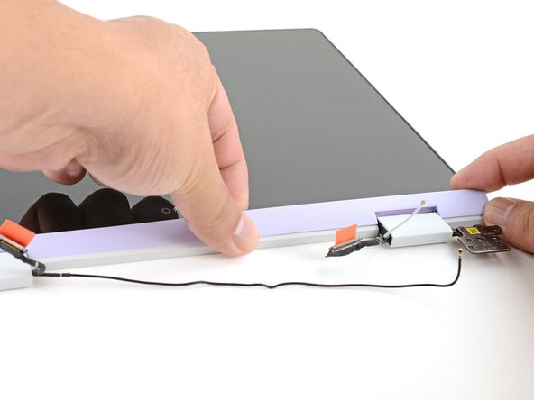
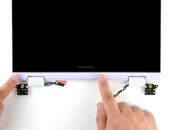
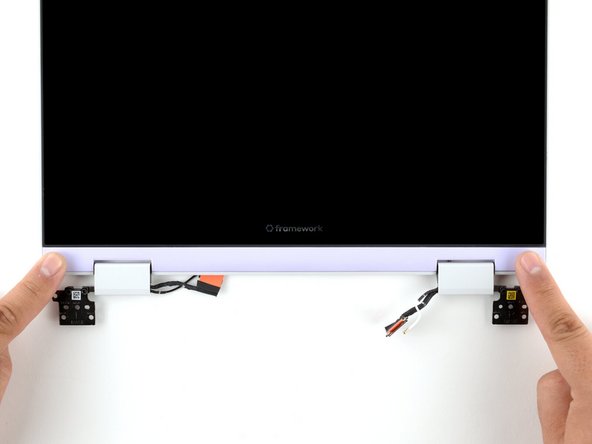
Slide your fingers under the top edge of the Display Cover to release it from the laptop.
-
-
-
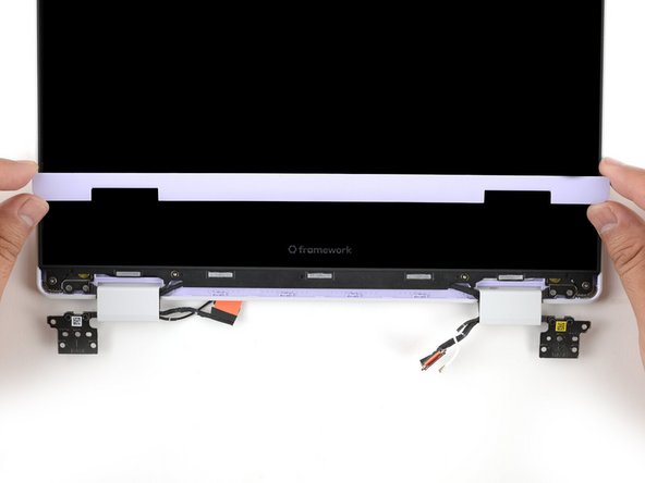
Remove the Display Cover.
-
-
-
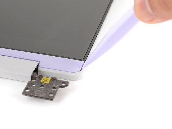
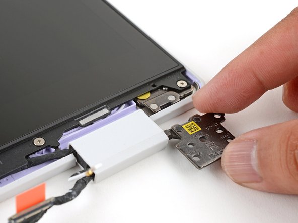
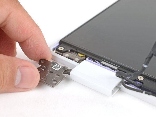
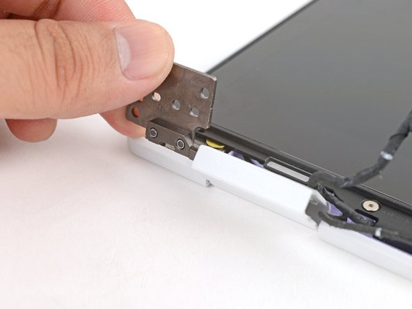
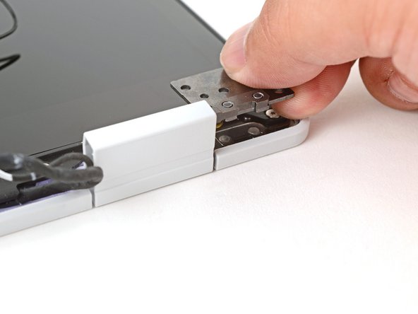
Use your fingers to twist the right hinge plate until it's flipped on top of the display.
-
The stiff hinge can be difficult to twist. Wear some work gloves, or use a cloth to help get a better grip.
-
-
-
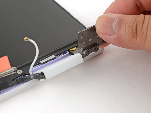
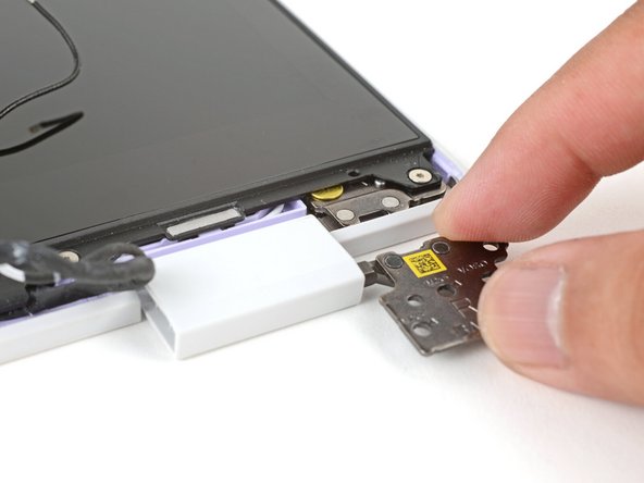
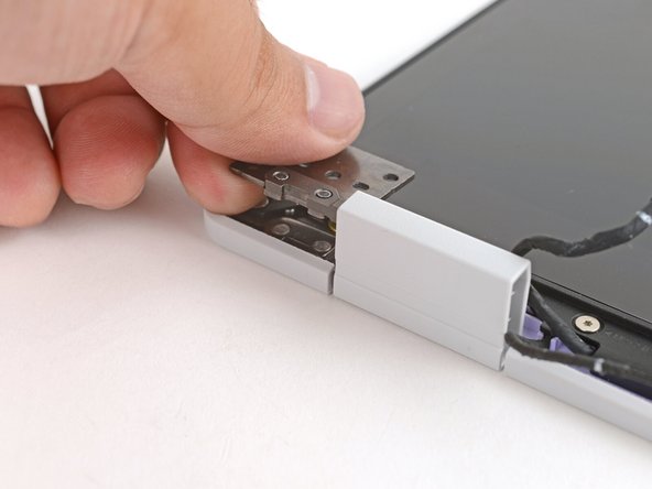
Twist the left hinge plate until it's flipped on top of the display.
-
-
-
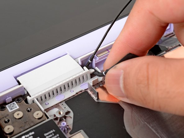
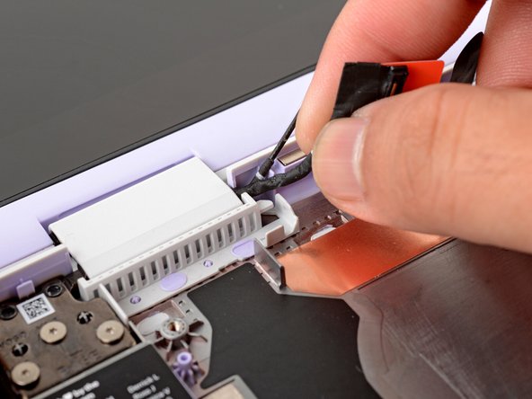
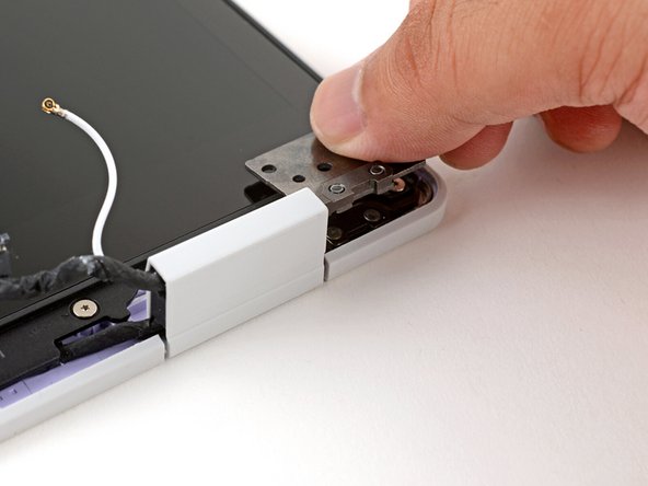
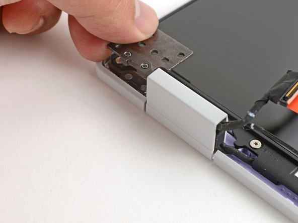
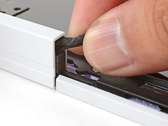
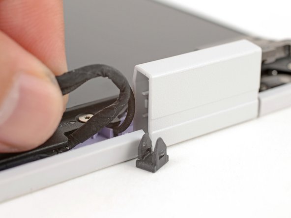
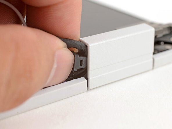
Use your fingers to grab the two cables coming out of the left hinge.
-
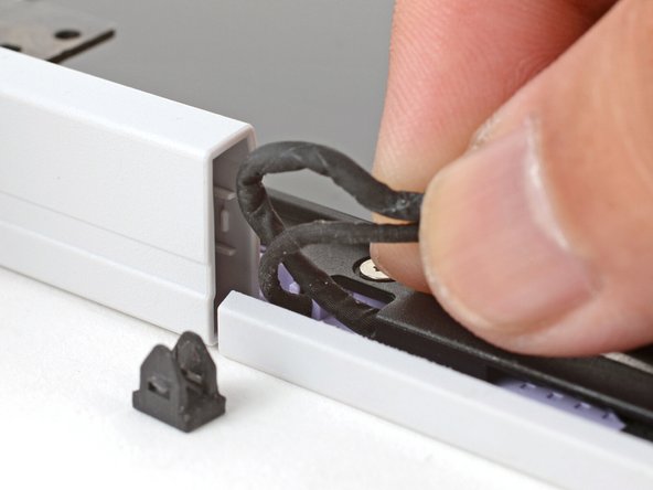
Pull gently to pop out the black cable clip and release the cables.
-
-
-
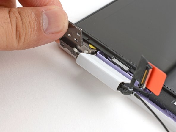
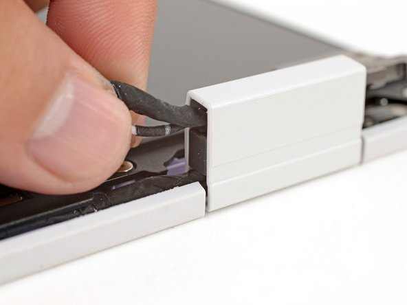
Repeat the procedure on the right hinge to release the cables.
-
-
-
Use your fingers to twist both hinge plates back down so they lay flat on your work surface.
-
-
-
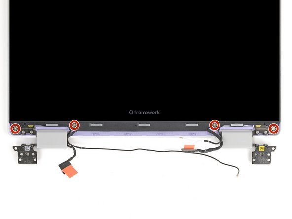
Use your Framework Screwdriver to remove the four 3.3 mm‑long T5 Torx screws securing the display to the Top Cover.
-
These screws are not captive. Store them in a safe location for reassembly.
-
-
-
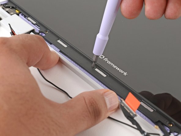
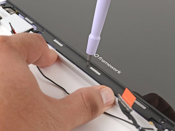
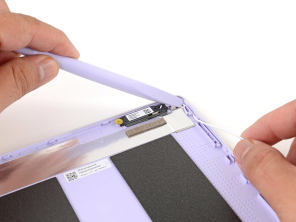
Use your fingers to hold the bottom edge of the Top Cover in place.
-
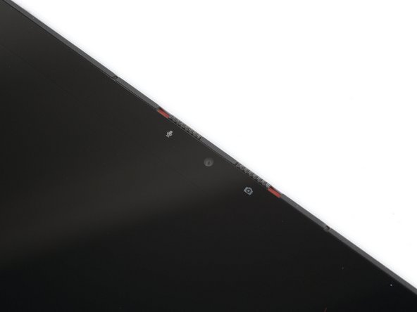
Insert the bit end of your Framework Screwdriver into the small hole on the display, below the Framework logo.
-
Slide the display down towards the hinge edge to release the tabs holding the top edge of the display in place.
-
-
-
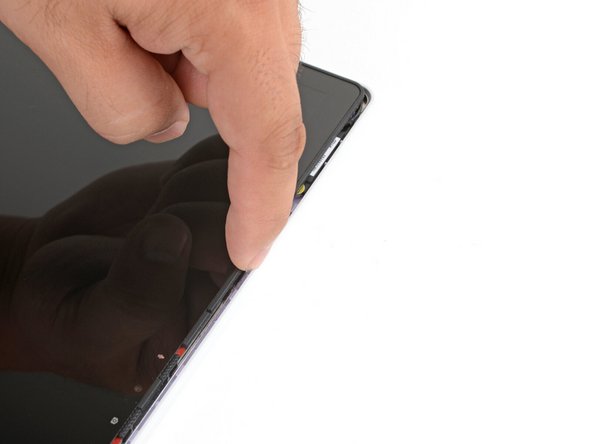
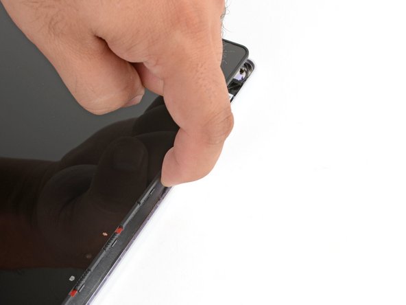
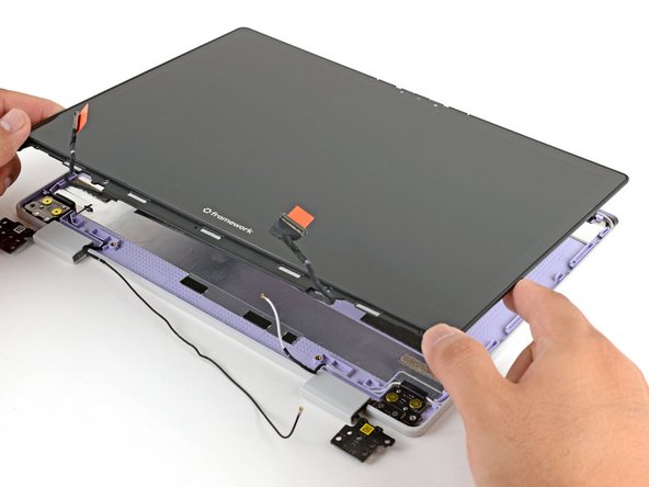
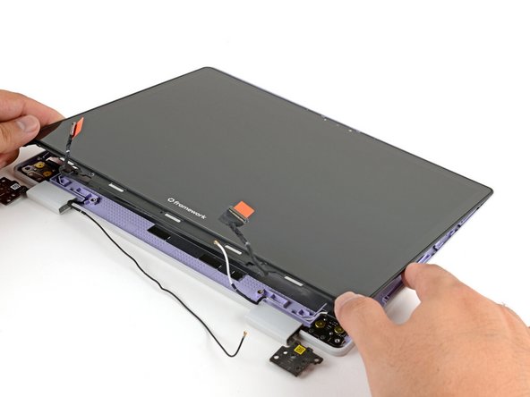
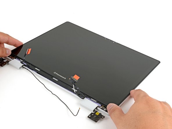
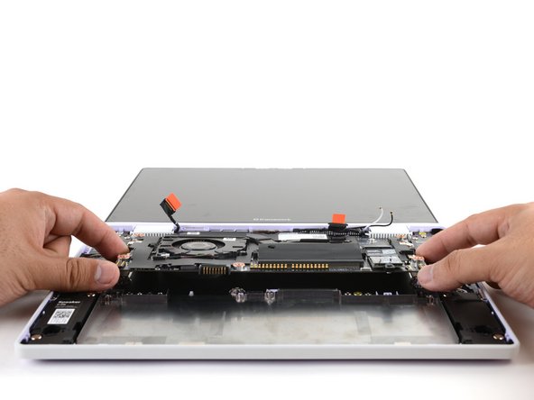
Use your fingers to lift the top edge of the display from the Top Cover.
-
-
-
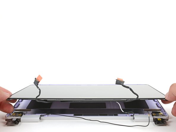
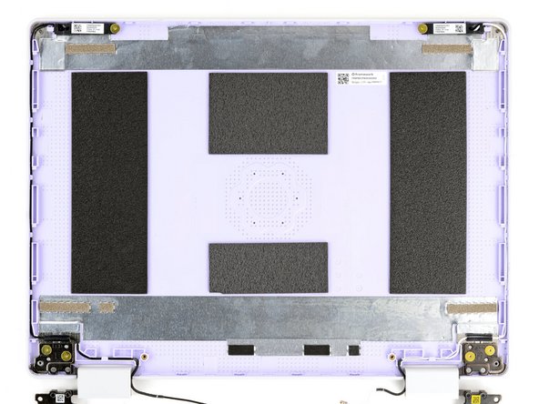
Lift and remove the display from the Top Cover.
-
-
-
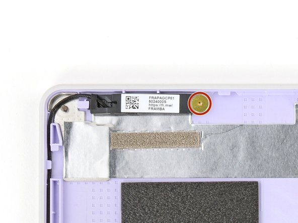
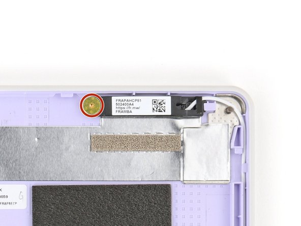
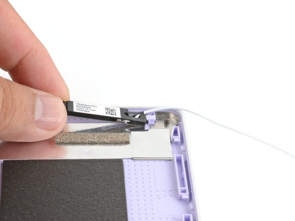
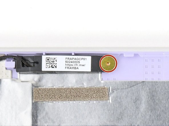
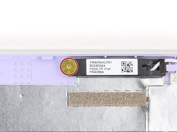
Use your Framework Screwdriver to remove the two (one per antenna) 2.5 mm‑long T5 Torx screws securing the antennas to the Top Cover.
-
-
-
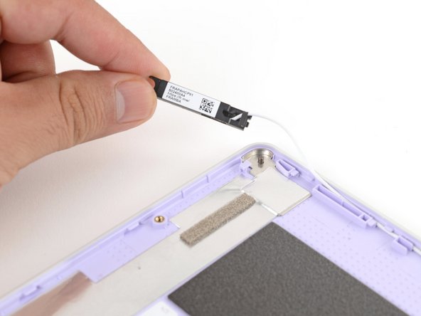
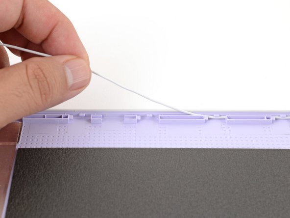
Use your fingers to lift the right antenna away from the Top Cover.
-
Carefully guide the white antenna cable out of its channel.
-
-
-
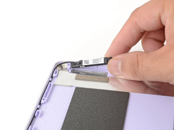
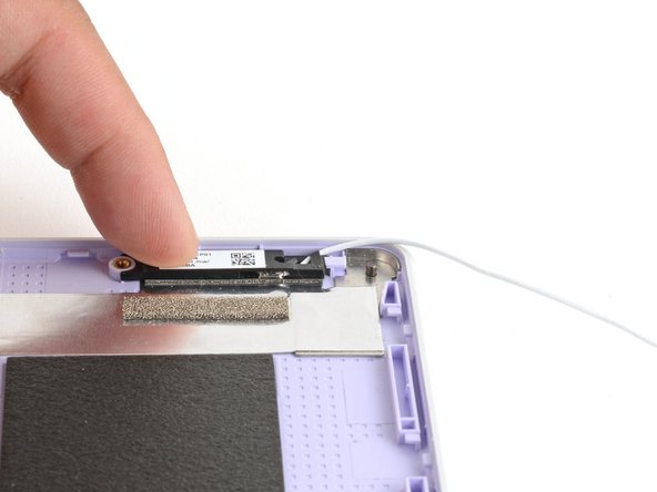
Use your fingers to lift the left antenna away from the Top Cover.
-
Carefully guide the black antenna cable out of its channel.
-
-
-
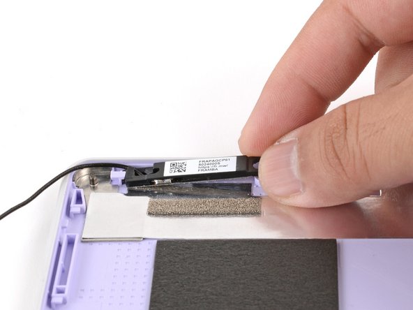
Remove the antennas.
-
-
-
Congratulations on completing disassembly! The remaining steps will show how to reassemble your Framework Laptop.
-
-
-
To install the antennas, you'll fasten them onto the frame first, then route each antenna cable into its Top Cover channel.
-
Lay each antenna in place in the Top Cover.
-
-
-
Use your Framework Screwdriver to install the two (one per antenna) 2.5 mm‑long T5 Torx screws to secure the antennas to the Top Cover.
-
-
-
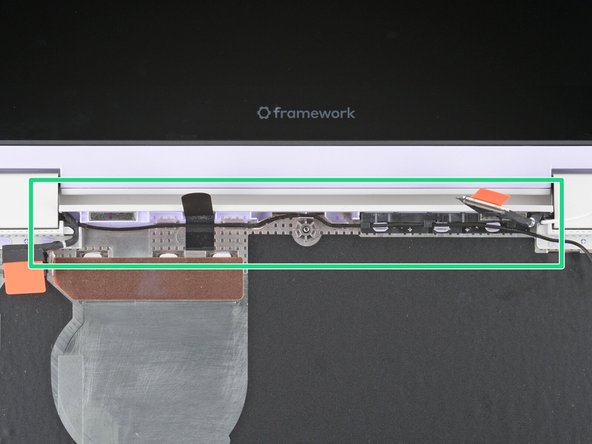
Use your fingers and your Framework Screwdriver to carefully guide each antenna cable back into its channel.
-
Zoom in on the second photo to see how the antenna cables sit in their channels.
-
-
-
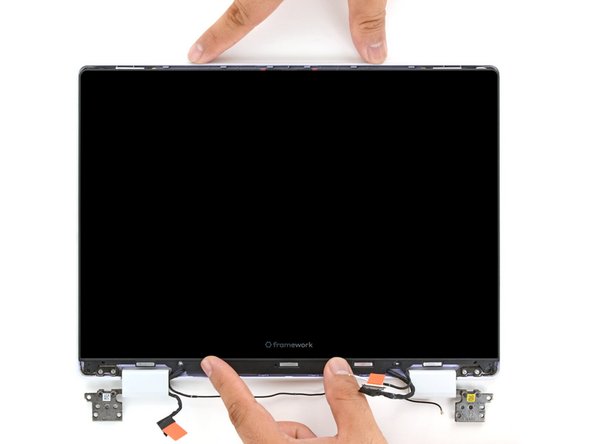
Lay the display in place in the Top Cover, such that the top edge of the display is slightly below the top edge of the Top Cover.
-
-
-
Use your fingers to slide the display upwards to latch the tabs on the top edge of the display.
-
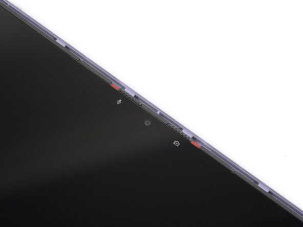
The top edge shouldn't have any gaps when the display's in place.
-
-
-
Use your Framework Screwdriver to install the four 3.3 mm‑long T5 Torx screws to secure the display to the Top Cover.
-
Make sure you don't accidentally install the 4.5 mm‑long hinge screws here. They look identical, but the hinge screws are longer.
-
Tighten the screws until they're snug. Don't over-tighten them, or you may damage the screw tabs.
-
-
-
Use your fingers to twist both hinge plates so they're flipped over the display.
-
-
-
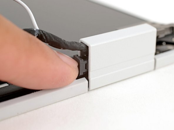
Place the cable clip around the right hinge cables, where they were bent from being inserted into the hinge.
-
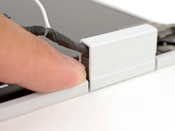
Use your fingers to press the clip into the hinge to secure the cables.
-
-
-
Repeat the procedure on the left hinge to secure the left cables.
-
-
-
Make sure both cable clips are fully inserted into the hinges, so that they won't be snagged when the hinges pivot.
-
-
-
Use your fingers to twist both hinge plates so that they lay flat on your work surface.
-
-
-
Lay the Display Cover in place below the display.
-
Use your finger to press along the length of the Display Cover to snap it onto the laptop.
-
-
-
Use your fingers to lift the Top Cover hinges over the Bottom Cover lip.
-
Lay the hinges in place in the Bottom Cover.
-
Use the plastic alignment pins to align each hinge in place.
-
-
-
Use your Framework Screwdriver to install the six 4.5 mm‑long T5 Torx screws securing the two hinges.
-
-
-
Use your fingers to gently press the webcam cable into its plastic channel.
-
-
-
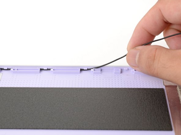
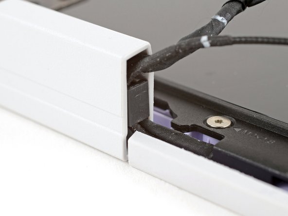
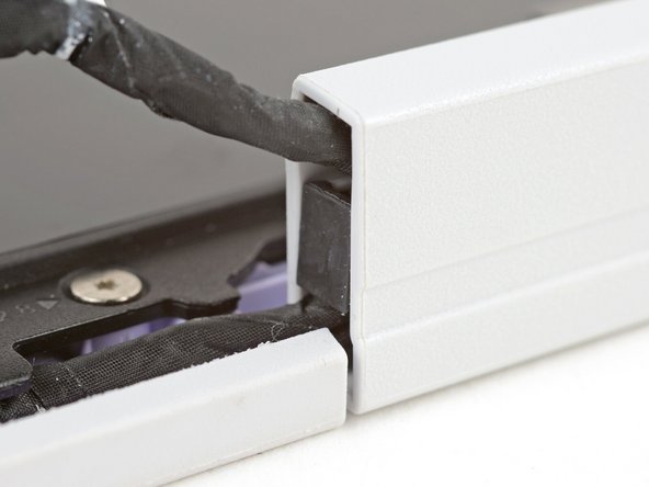
Use your fingers and your Framework Screwdriver to carefully press and guide the black antenna cable back into its channel.
-
Zoom in on the second image to see how the antenna cable sits in its channel.
-
-
-
Press the black loop over the antenna cable and onto the Bottom Cover. If it doesn't stick, use a bit of thin double-sided tape to hold it down.
-
-
-
Carefully lay the Mainboard in the laptop.
-
Use the two alignment pins to help align the Mainboard to the laptop.
-
Be careful not to trap the webcam, display, and antenna cables under the Mainboard as you set it in place.
-
-
-
Use your Framework Screwdriver to tighten the five captive T5 Torx screws to secure the Mainboard.
-
-
-
Use your fingers to grab the orange tab on the display cable, located near the right hinge.
-
Align and press the display cable straight down onto its connector.
-
-
-
Use your fingers to grab the orange tab on the webcam cable, located near the left hinge.
-
Align and press the webcam cable straight down onto its connector.
-
-
-
Hold the Wi-Fi card by its edges. Don't touch the gold contacts with your fingers. If you do, wipe the contacts with a clean, lint-free cloth to remove any finger oils.
-
Align the Wi-Fi card's gold contacts and notch with the socket on the Mainboard.
-
Insert the Wi-Fi card into the socket at a shallow angle. The gold contacts should mostly be covered by the socket.
-
The Wi-Fi card fits into the socket in one orientation. If it doesn't fit, try flipping the module.
-
-
-
Hold the Wi-Fi card down with your finger.
-
Position the black antenna cable connector over the left Wi-Fi card's coaxial socket.
-
Tweezers can help position the connector.
-
Use your finger to press the connector into place. You should feel a faint click, and the cable will stay attached to the socket by itself.
-
These connectors are very delicate! If the connector doesn't feel like it's clicking in place, reposition the connector and try again.
-
Repeat the procedure with the white antenna cable.
-
-
-
Slide the Wi-Fi bracket over the top edge of the Wi-Fi card.
-
-
-
Use your Framework Screwdriver to tighten the captive T5 Torx screw to secure the Wi-Fi card.
-
-
-
Use your fingers to lay the Power Button Board in place.
-
Use the two plastic pins on the laptop to align the Power Button Board.
-
-
-
Use your Framework Screwdriver to tighten the captive T5 Torx screw to secure the Power Button Board.
-
Tighten the screw until it's snug. Don't over-tighten it, or you may strip the screw.
-
-
-
Insert the Audio Board into the laptop at an angle to help align the headphone jack.
-
Use the two plastic alignment pins on the laptop to help with final alignment.
-
-
-
Use your Framework Screwdriver to tighten the captive T5 Torx screw to secure the Audio Board.
-
Tighten the screw until it's snug. Don't over-tighten it, or you may strip the screw.
-
-
-
Lay the battery in its recess in the laptop.
-
-
-
Use your finger to push the battery down near its connector to reconnect it.
-
-
-
Use your Framework Screwdriver to tighten the six captive T5 Torx screws to secure the battery.
-
Tighten the screws until they're snug. Don't over-tighten them, or you may strip the screws.
-
-
-
Angle the bottom edge of the Input Cover towards the base of the laptop.
-
Align and insert the bottom edge of the Input Cover into the base of the laptop.
-
Make sure the slots along the bottom edge of the Input Cover slide into the tabs in the base.
-
Lower the Input Cover's top edge onto the laptop until the magnets snap it in place.
-
Make sure the Input Cover sits neatly within the laptop frame and no corners are popping up.
-
-
-
Close the laptop lid.
-
Flip your laptop face-down on a clean work surface.
-
-
-
Use your Framework Screwdriver to tighten the eight captive T5 Torx screws on the bottom of your laptop.
-
Tighten the screws until they're snug. Don't over-tighten them, or you may strip the screws.
-
-
-
Slide each Expansion Card into its Expansion Card slot.
-
-
-
If there's a red bar showing under either Expansion Card latch, use your finger to flip the latch and lock the Expansion Card into its slot.
-
Locking the Expansion Card slots helps keep the cards in place when you unplug cables from them.
-


You finished fixing your Framework Laptop!
Take your e-waste to an R2 or e-Stewards certified recycler.
If you need help, contact Framework support.
You finished fixing your Framework Laptop!
Take your e-waste to an R2 or e-Stewards certified recycler.
If you need help, contact Framework support.